 Small batches, high standards. Our rapid prototyping service makes validation faster and easier —

Sheet Metal For Fabrication: Match Materials To Methods Like A Pro
What Makes Sheet Metal Ideal for Fabrication Projects
When you're planning a manufacturing project, selecting the right material isn't just a minor detail—it's the foundation that determines everything from production efficiency to final product quality. But what exactly separates fabrication-grade metal sheets from the generic metal products you might find at a hardware store?
Sheet metal fabrication is the process of transforming flat metal sheets into functional components through cutting, bending, forming, and joining operations. Fabrication-grade sheet metal specifically refers to metal sheets manufactured to precise thickness tolerances, surface quality standards, and mechanical property specifications required for professional manufacturing processes.
Defining Fabrication-Grade Sheet Metal
Not all metal sheet products are created equal. Fabrication-grade materials must meet stringent requirements that general-purpose metals simply don't address. Think of it this way: you wouldn't use construction lumber for fine furniture making, and similarly, professional sheet metal working demands materials engineered for precision.
What distinguishes fabrication-grade sheet metal? Three critical characteristics set it apart:
- Precise thickness consistency: Fabrication-grade materials maintain tight dimensional tolerances across the entire sheet, typically within thousandths of an inch. This consistency ensures predictable behavior during bending, cutting, and forming.
- Controlled surface quality: The surface finish must be free from defects like scale, pitting, or excessive oxidation that could interfere with laser cutting, welding, or finishing operations.
- Certified mechanical properties: Tensile strength, ductility, and hardness values are documented and consistent, allowing engineers to accurately predict how the material will perform during and after fabrication.
According to industry specifications, fabrication processes like bending, drawing, and punching require materials that can withstand significant manipulation without cracking or deforming unpredictably. This is why metal fabrication facilities carefully source materials with verified properties rather than using commodity-grade products.
Why Material Selection Drives Project Success
Here's something many project managers learn the hard way: the cheapest sheet metal rarely delivers the lowest total project cost. When you understand what is metal fabrication at its core—manipulating metal into precise shapes through controlled processes—you recognize why material selection matters so fundamentally.
Consider what happens when you choose the wrong material:
- Inconsistent thickness leads to springback variations during bending, causing dimensional inaccuracies
- Poor surface quality creates contamination in welds, resulting in weak joints or rejection during quality inspection
- Unknown mechanical properties make it impossible to calculate proper bend radii, often resulting in cracked parts
The relationship between material and method is inseparable in successful metal fabrication. As Protolabs explains, different steel compositions directly impact manufacturability—low-carbon steels with carbon content typically below 0.25% are ideal for optimal cold-forming in sheet metal work and general fabrication due to their excellent formability and weldability, while higher carbon content increases strength but reduces workability.
This guide takes a material-first approach to sheet metal for fabrication because your material choice influences every downstream decision. Whether you're producing automotive components, architectural panels, or industrial enclosures, understanding your metal's properties before selecting fabrication methods eliminates costly trial-and-error and positions your project for success from the start.
Types of Sheet Metal Materials for Fabrication
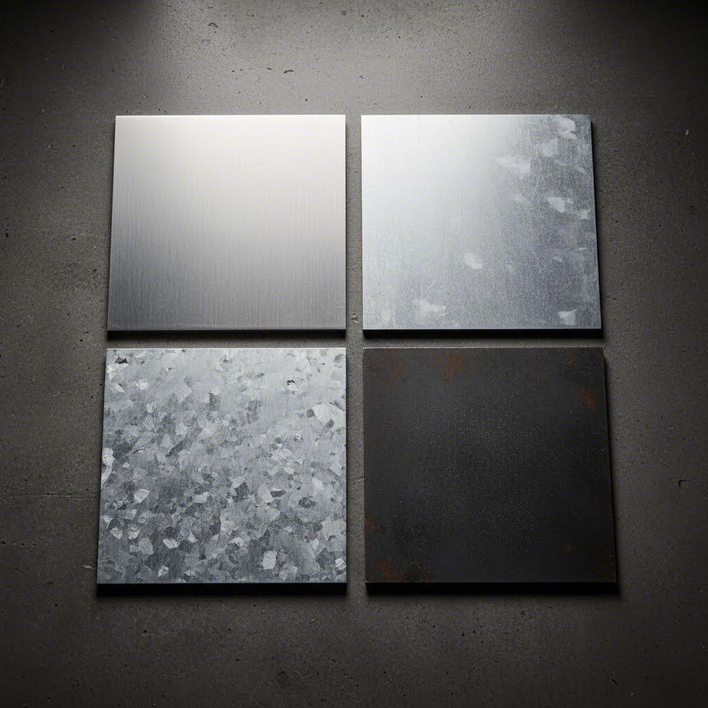
Now that you understand what makes sheet metal suitable for fabrication, let's explore your actual material options. Choosing between carbon steel, stainless steel, aluminum, or galvanized steel isn't just about cost—it's about matching material properties to your specific fabrication methods and end-use requirements.
Each material family behaves differently under cutting, bending, and welding operations. Understanding these differences upfront prevents costly mistakes and helps you achieve consistent, high-quality results.
| Material Type | Common Grades | Tensile Strength Range | Best Fabrication Methods | Typical Applications |
|---|---|---|---|---|
| Carbon Steel | A36, 1018, 1020, 4130 | 58,000–95,000 psi | Laser cutting, MIG welding, CNC bending | Structural components, machinery, automotive frames |
| Stainless Steel | 304, 316, 430 | 73,000–90,000 psi | Laser cutting, TIG welding, forming | Medical equipment, food processing, architectural |
| Aluminum | 3003, 5052, 6061 | 16,000–45,000 psi | CNC punching, bending, TIG welding | Enclosures, aerospace, lightweight structures |
| Galvanized Steel | G90, G60 (coating weight) | 42,000–65,000 psi | Punching, roll forming, spot welding | HVAC ducts, outdoor equipment, roofing |
Carbon Steel Varieties for Structural Applications
Carbon steel remains the workhorse of metal fabrication for good reason. It offers an excellent balance of strength, formability, and cost-effectiveness that few other materials can match. But not all carbon steel grades perform equally in fabrication environments.
According to Industrial Metal Service, carbon steel is classified based on carbon content: low-carbon (under 0.3%), medium-carbon (0.3–0.6%), and high-carbon (above 0.6%). For sheet metal fabrication, low-carbon grades dominate because they're soft, easy to shape, and simple to weld.
Here's what you need to know about the most common grades:
- A36: The go-to structural steel plate for general fabrication. It welds beautifully, bends without cracking, and costs less than specialty grades. You'll find it in brackets, frames, and machinery bases.
- 1018: A mild steel with slightly more carbon (0.18%), offering improved machinability while remaining highly formable. Excellent for parts requiring secondary machining operations.
- 1020: Contains 0.2% carbon, providing a modest strength increase over 1018 while maintaining good weldability. Common in automotive and general manufacturing.
- 4130: A chromium-molybdenum alloy steel with superior strength-to-weight ratio. Requires more careful welding procedures but delivers exceptional performance in aerospace and high-stress applications.
Stainless Steel Grades and Their Fabrication Advantages
When corrosion resistance matters, stainless steel sheet becomes your material of choice. The minimum 10.5% chromium content creates a protective oxide layer that shields against rust and environmental degradation—making it indispensable for food processing, medical, and outdoor applications.
However, stainless steel sheet metal presents unique fabrication challenges. It work-hardens quickly during forming operations, requires different cutting parameters than carbon steel, and demands cleaner welding environments to maintain corrosion resistance.
The two most popular grades for fabrication are:
- 304 Stainless: The most widely used austenitic grade, containing approximately 18% chromium and 8% nickel. It offers excellent formability, weldability, and corrosion resistance for indoor and mildly corrosive environments. Think kitchen equipment, architectural trim, and general-purpose enclosures.
- 316 Stainless Steel: Adds molybdenum to the mix, significantly improving resistance to chlorides and marine environments. It's the standard choice for chemical processing, pharmaceutical equipment, and coastal installations. Expect to pay 20–30% more than 304, but the enhanced durability justifies the investment in harsh conditions.
According to Metaltech, understanding the three-digit SAE grading system helps you quickly identify stainless steel families: 300-series denotes austenitic (non-magnetic, highly formable), 400-series indicates ferritic or martensitic (magnetic, heat-treatable).
Aluminum Sheet Metal for Lightweight Solutions
When weight reduction is critical, aluminum sheet metal delivers strength-to-weight ratios that steel simply can't match. An aluminum sheet typically weighs about one-third as much as equivalent steel plate while still providing adequate structural performance for many applications.
The trade-off? Aluminum requires adjusted fabrication parameters. It melts at lower temperatures, transfers heat rapidly during welding, and exhibits more springback during bending operations. Successful aluminum fabrication demands experience and proper equipment setup.
Common fabrication grades include:
- 3003: A general-purpose alloy with excellent formability and weldability. It's the most common aluminum sheet for HVAC, chemical equipment, and decorative applications.
- 5052: Offers higher strength than 3003 with excellent corrosion resistance, particularly in marine environments. Ideal for fuel tanks, pressure vessels, and structural components.
- 6061: A heat-treatable alloy that achieves the highest strength among common sheet grades. Widely used in aerospace, automotive, and structural applications where strength-to-weight ratio is paramount.
Galvanized Sheet Metal: Hot-Dip vs. Electrogalvanized
Galvanized sheet metal offers carbon steel's workability with enhanced corrosion protection—a zinc coating sacrificially protects the underlying steel. But the two galvanizing methods produce dramatically different results for fabrication.
Steel Supply L.P. explains the critical differences:
- Hot-dipped galvanized: Steel is immersed in molten zinc, creating a thick, durable coating averaging 20–50 years of protection. The coating appears matte gray and may have visible crystalline patterns (spangle). Best for structural applications, outdoor equipment, and long-term installations. However, the thicker coating can cause issues during precision bending and creates hazardous zinc fumes during welding.
- Electrogalvanized: An electrochemical process bonds a thinner, more uniform zinc layer to the steel surface. This produces a smoother finish ideal for painting and precision forming. The thinner coating offers less corrosion protection but behaves more predictably during fabrication—making it preferred for automotive panels, appliances, and indoor applications.
For fabrication purposes, electrogalvanized material is generally easier to work with. It bends more consistently, welds more cleanly (though ventilation remains essential), and accepts paint without special preparation. Reserve hot-dipped material for situations where maximum corrosion protection outweighs fabrication convenience.
Understanding these material differences positions you to make informed choices before cutting begins. But material is only half the equation—the next critical factor is selecting the right thickness for your application.
Sheet Metal Gauge Chart and Thickness Specifications
You've selected your material—now comes an equally critical decision that trips up even experienced fabricators: choosing the right thickness. Here's where things get counterintuitive. Unlike standard metric measurements, the sheet metal gauge system follows an inverse relationship that can confuse newcomers and lead to costly ordering mistakes.
Understanding the Gauge Numbering System
Imagine a measuring system where bigger numbers mean smaller sizes. Sounds backwards? That's exactly how the gauge system works. According to Xometry, gauge numbers originated from historical wire-drawing operations, where the number represented how many times metal was drawn through progressively smaller dies. The result: lower gauge numbers indicate thicker material, while higher numbers mean thinner sheets.
For example, 10-gauge steel measures approximately 3.4 mm (0.1345 inches)—suitable for heavy-duty structural components. Jump to 24-gauge, and you're working with material only 0.61 mm (0.024 inches) thick, appropriate for decorative panels or light enclosures.
Here's what makes gauge specifications even trickier: the same gauge number produces different thicknesses depending on the material. A 16-gauge steel sheet is not the same thickness as 16-gauge aluminum or stainless steel. This variation exists because gauge measurements were historically based on weight per square foot, and different metals have different densities.
| Gauge | Steel (inches) | Steel (mm) | Stainless Steel (inches) | Stainless Steel (mm) | Aluminum (inches) | Aluminum (mm) |
|---|---|---|---|---|---|---|
| 10 | 0.1345 | 3.42 | 0.1406 | 3.57 | 0.1019 | 2.59 |
| 11 | 0.1196 | 3.04 | 0.1200 | 3.18 | 0.0907 | 2.30 |
| 12 | 0.1046 | 2.66 | 0.1094 | 2.78 | 0.0808 | 2.05 |
| 14 | 0.0747 | 1.90 | 0.0781 | 1.98 | 0.0641 | 1.63 |
| 16 | 0.0598 | 1.52 | 0.0625 | 1.59 | 0.0508 | 1.29 |
| 18 | 0.0478 | 1.21 | 0.0500 | 1.27 | 0.0403 | 1.02 |
| 20 | 0.0359 | 0.91 | 0.0375 | 0.95 | 0.0320 | 0.81 |
| 22 | 0.0299 | 0.76 | 0.0313 | 0.79 | 0.0253 | 0.64 |
| 24 | 0.0239 | 0.61 | 0.0250 | 0.64 | 0.0201 | 0.51 |
Notice how 11 gauge steel thickness measures 3.04 mm, while the same gauge in aluminum is only 2.30 mm. Similarly, 14 gauge steel thickness comes in at 1.90 mm—nearly 17% thicker than 14-gauge aluminum. When specifying materials, always confirm both the gauge number and the actual dimensional thickness to avoid surprises. Just as you'd consult a drill size chart or drill bit size chart for precise hole dimensions, referencing a sheet metal gauge chart ensures you're ordering exactly what your design requires.
Thickness Tolerances That Impact Fabrication Quality
Even when you specify the correct gauge, manufacturing tolerances mean the actual thickness can vary. According to MetalsCut4U, sheet metal gauge measurements provide reliable thickness indications, but variations occur due to manufacturing tolerances—and these variations directly impact your fabrication outcomes.
Why does this matter? Consider bending operations. The force required to bend metal and the resulting springback depend on material thickness. A sheet that's 5% thicker than expected requires more bending force and exhibits different springback characteristics, potentially throwing off your dimensional accuracy.
For welding operations, thickness inconsistencies create similar problems. Your welder may set parameters for 16-gauge material, but if the actual thickness varies across the sheet, penetration depth and heat distribution become unpredictable—leading to weak joints or burn-through.
When specifying gauge for different fabrication processes, consider these key factors:
- For laser cutting: Thicker gauges (10–14) require more power and slower speeds. The heat-affected zone increases with thickness, potentially altering material properties near cut edges. Confirm your laser cutter's maximum capacity before specifying heavy gauges.
- For bending operations: Each gauge has a minimum bend radius to prevent cracking. Thicker materials need larger radii and more tonnage. Always verify your press brake capacity matches your gauge selection.
- For welding: Thin gauges (20–24) risk burn-through with excessive heat input. Thick gauges (10–12) require more powerful equipment and longer weld times. Match your welding process to the gauge range.
- For structural applications: Heavier gauges (10–14) provide greater load-bearing capacity but add weight and cost. Calculate actual structural requirements rather than defaulting to "thicker is better."
- For forming and drawing: Thinner gauges (18–24) form more easily but may require multiple operations. Consider material flow and potential thinning at corners and draw depths.
Standard tolerance ranges typically fall within ±0.003" to ±0.007" for common gauges, though tighter tolerances are available at premium pricing. When your application demands precise fit-up—such as interlocking components or tight clearance assemblies—specify the tolerance band rather than relying on standard mill tolerances.
Understanding gauge sizes and their tolerances prepares you for informed material ordering. But knowing your material and thickness is just the beginning—the real skill lies in matching these specifications to the right fabrication processes.
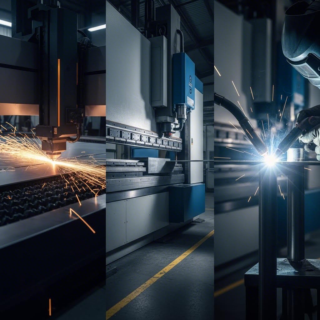
Matching Sheet Metal to Fabrication Processes
You've selected your material and specified the right gauge—now comes the decision that determines whether your project runs smoothly or becomes a troubleshooting nightmare. How do you know which fabrication processes will work best with your chosen sheet metal?
The answer lies in understanding how material properties interact with each fabrication method. Tensile strength affects cutting speeds and tool wear. Ductility determines whether your bends crack or form cleanly. Thermal conductivity influences everything from laser cutting efficiency to welding distortion. Let's break down these relationships so you can match materials to methods like a seasoned fabricator.
| Material | Laser Cutting | Punching | Bending | Welding |
|---|---|---|---|---|
| Carbon Steel | Excellent | Excellent | Excellent | Excellent |
| Stainless Steel (304) | Good | Good | Good | Excellent |
| Stainless Steel (316) | Good | Fair | Good | Good |
| Aluminum (3003/5052) | Good | Excellent | Excellent | Fair |
| Aluminum (6061) | Good | Good | Good | Fair |
| Galvanized Steel | Fair | Excellent | Excellent | Fair (fume concerns) |
Laser Cutting Compatibility Across Metal Types
When you feed a sheet into a laser cutter, several material properties immediately come into play. The laser's ability to cut cleanly depends on how the material absorbs energy, conducts heat, and responds to rapid temperature changes.
Carbon steel cuts beautifully with laser technology. Its moderate thermal conductivity allows the laser beam to concentrate heat at the cut zone without excessive dissipation. The result? Clean edges, minimal dross, and predictable kerf widths. Most fabrication shops consider carbon steel the benchmark for laser cutting performance.
Stainless steel presents more challenges. Higher chromium content creates reflectivity issues, and the material's lower thermal conductivity can cause heat buildup around the cut. You'll notice slightly rougher edges compared to carbon steel, and cutting speeds typically drop 20–30% for equivalent thicknesses.
Aluminum requires careful parameter adjustment due to its high reflectivity and thermal conductivity. The material wants to reflect laser energy rather than absorb it, and any heat that does penetrate spreads rapidly. Modern fiber lasers handle aluminum well, but CO2 lasers struggle with reflective surfaces.
Key laser cutting parameters to consider:
- Kerf width: The material removed during cutting typically ranges from 0.1–0.4 mm depending on material type and thickness. Aluminum produces wider kerf than steel due to higher thermal conductivity spreading the heat zone.
- Heat-affected zone (HAZ): Stainless steel and aluminum show larger HAZ than carbon steel. For critical applications, factor this into your tolerance calculations.
- Edge quality: Carbon steel produces the cleanest edges. Stainless may show slight discoloration. Aluminum edges often require secondary deburring.
- Maximum thickness: Your laser cutter's power rating determines cutting capacity. A 4kW fiber laser handles 20mm carbon steel but only 12mm stainless or 8mm aluminum at comparable quality levels.
Bending and Forming Considerations by Material
Bending seems straightforward until springback ruins your first batch of parts. Every material wants to return partially to its original shape after bending—understanding how much springback to expect saves countless hours of trial-and-error.
Low-carbon steel remains the easiest material to bend accurately. Its excellent ductility allows tight radii without cracking, and springback stays predictable in the 1–3 degree range for typical bends. Most press brake operators develop intuition for steel springback quickly.
Stainless steel work-hardens during bending, meaning each bend attempt makes the material harder and more resistant to further forming. Plan your bend sequence carefully—you typically get one clean shot before the material becomes difficult to work. Springback increases to 3–5 degrees, requiring overbending compensation.
Aluminum exhibits the most dramatic springback, often 5–10 degrees depending on the alloy and temper. The material's lower tensile strength means it bends easily, but returning to shape aggressively. Experienced fabricators routinely overbend aluminum by 10% or more to achieve target angles.
Critical bending parameters by material:
- Minimum bend radius: Carbon steel tolerates radii equal to material thickness. Stainless requires 1.5–2x thickness. Aluminum varies dramatically by alloy—3003 bends tightly, while 6061-T6 needs 3x thickness minimum to avoid cracking.
- Grain direction: Bending perpendicular to the grain direction reduces cracking risk across all materials. This matters most for stainless steel and heat-treated aluminum alloys.
- Tonnage requirements: Stainless steel requires approximately 50% more tonnage than equivalent carbon steel. Aluminum needs about 60% of carbon steel's tonnage.
- Surface finish impact: Mill finish materials bend predictably. Polished or brushed surfaces may show marking from tooling contact—consider protective film or padded dies for visible surfaces.
Welding Requirements for Different Sheet Metals
Choosing between welding processes—particularly the decision of mig vs tig welding—depends heavily on your material selection. Each sheet metal type brings unique challenges that favor certain welding approaches.
According to Online Metals, the weldability of steel grades depends mostly on hardness, which correlates directly with carbon content. Low-carbon steels with less than 0.25% carbon weld easily with virtually any process. As carbon content increases, the risk of cracking rises, requiring low-hydrogen processes and careful heat management.
When evaluating tig vs mig welding for your project, consider these material-specific factors:
Carbon Steel: Both MIG and TIG work exceptionally well. MIG welding offers faster deposition rates for thicker gauges and production work. TIG provides superior control for thin materials and visible welds. Most fabrication shops default to MIG for carbon steel efficiency.
Stainless Steel: TIG welding dominates for stainless applications requiring corrosion resistance. The precise heat control prevents carbide precipitation that can compromise the protective chromium oxide layer. MIG works for non-critical applications but may introduce more spatter and heat distortion.
Aluminum Welding: This material demands specialized approaches due to its oxide layer and high thermal conductivity. TIG welding with AC current remains the gold standard for aluminum welding, providing the heat control needed to avoid burn-through while breaking through the aluminum oxide layer. MIG with pulse settings works for thicker gauges but requires experienced operators.
Welding process selection criteria:
- Weldability ratings: Low-carbon steel rates excellent. Stainless steel rates excellent with proper technique. Aluminum rates fair to good, requiring more skill and specialized equipment.
- Filler metal matching: Always match filler composition to base metal. Using incorrect filler creates weak joints and potential corrosion cells in dissimilar metal combinations.
- Shielding gas: Carbon steel uses CO2 or argon-CO2 mixes. Stainless steel requires pure argon or argon-helium. Aluminum uses pure argon exclusively.
- Distortion management: Thinner gauges (20–24) distort easily from weld heat. Stitch welding, proper fixturing, and controlled heat input prevent warping—especially critical for aluminum's high thermal conductivity.
Surface Finish Impact on Fabrication Approach
Your material's surface condition influences every fabrication step, yet many project planners overlook this factor until problems emerge. Mill finish, polished, brushed, or pre-coated surfaces each require adjusted handling.
Mill finish materials—the default state from the rolling process—offer the most forgiving fabrication characteristics. Oils and scale present during cutting and welding burn away or become inconsequential. However, visible applications require post-fabrication finishing.
Pre-finished surfaces demand protective measures throughout fabrication. Laser cutting may discolor polished edges. Press brake tooling can scratch brushed finishes. Welding spatter permanently damages coatings. Consider these trade-offs when specifying surface requirements:
- Polished stainless: Use protective film during handling. Avoid excessive laser power that causes edge discoloration. Plan for touch-up polishing after welding.
- Brushed aluminum: Grain direction must align across joined pieces. Scratches from handling become permanent defects. Consider fabricating with mill finish and brushing after assembly.
- Pre-painted or powder-coated: Remove coating from weld zones before joining. Heat from welding and cutting damages coatings beyond repair—touch-up or full refinishing is typically required.
Understanding how your chosen material interacts with each fabrication process eliminates guesswork and reduces scrap rates. But even with perfect process matching, design decisions can make or break your fabrication success—which brings us to the principles of designing specifically for sheet metal manufacturing.
Design for Manufacturability in Sheet Metal Work
You've selected the right material, specified the correct gauge, and matched your fabrication processes—but here's where many projects stumble. Poor design decisions can transform a perfectly viable sheet metal prototype into an expensive manufacturing nightmare. The difference between a design that flows through production and one that requires constant rework comes down to understanding Design for Manufacturability (DFM) principles.
Think of DFM as the bridge between your CAD model and reality. What looks perfect on screen may crack during steel sheet bending, distort during welding, or require expensive secondary operations that blow your budget. According to Consac, design changes become exponentially more expensive as a project progresses—meaning early attention to manufacturability pays dividends throughout the product lifecycle.
Bend Radius Rules That Prevent Cracking
Ever watched a part crack along a bend line? That failure usually traces back to one simple mistake: specifying a bend radius too tight for the material. Each metal type has a minimum bend radius based on its ductility, thickness, and grain structure. Violate these limits, and the outer surface of your bend stretches beyond its capacity, resulting in fractures.
The general rule? Your minimum inside bend radius should equal or exceed the material thickness for most applications. But this baseline shifts significantly depending on what you're forming:
| Material Type | Minimum Bend Radius | Recommended Bend Radius | Notes |
|---|---|---|---|
| Low-Carbon Steel | 1× thickness | 1.5× thickness | Very forgiving; tight bends achievable |
| Stainless Steel (304) | 1.5× thickness | 2× thickness | Work-hardens; larger radii improve formability |
| Stainless Steel (316) | 2× thickness | 2.5× thickness | Less ductile than 304; requires conservative design |
| Aluminum (3003, 5052) | 1× thickness | 1.5× thickness | Soft alloys bend easily |
| Aluminum (6061-T6) | 3× thickness | 4× thickness | Heat-treated; significantly less ductile |
| Galvanized Steel | 1× thickness | 2× thickness | Coating may crack at tight radii |
Grain direction matters more than many designers realize. When forming steel sheet, bending perpendicular to the rolling direction (across the grain) significantly reduces cracking risk. If your part requires bends in multiple directions, position the most critical or tightest bend perpendicular to the grain whenever possible.
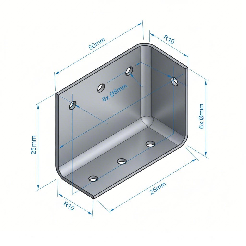
Hole Placement and Edge Distance Requirements
Placing holes too close to bends or edges ranks among the most common—and costly—design mistakes in precision sheet metal fabrication. During bending operations, metal stretches on the outside of the bend and compresses on the inside. Holes positioned within this deformation zone become distorted, pulling out of round or shifting position entirely.
The minimum safe distance from a hole center to a bend line equals 2× the material thickness plus the bend radius. For a 16-gauge steel part (1.52 mm) with a 2 mm bend radius, that means keeping hole centers at least 5 mm from the bend.
Edge distances follow similar logic. According to industry DFM guidelines, placing holes closer than 2× material thickness from a bend causes distortion because the metal stretches during bending, pulling holes out of shape or specification.
| Design Feature | Carbon Steel | Stainless Steel | Aluminum |
|---|---|---|---|
| Minimum hole diameter | 1× thickness | 1× thickness | 1× thickness |
| Hole-to-edge distance | 2× thickness | 2.5× thickness | 2× thickness |
| Hole-to-bend distance | 2× thickness + bend radius | 2.5× thickness + bend radius | 2× thickness + bend radius |
| Hole-to-hole spacing | 2× thickness | 2× thickness | 2× thickness |
| Relief cut depth | 1–1.5× thickness | 1.5× thickness | 1–1.5× thickness |
Relief cuts deserve special attention. Without proper relief cuts at corners and intersecting bends, material tears and corners deform. Always provide relief proportional to material thickness—typically 1–1.5× the thickness works for most sheet metal shapes.
Design Features That Reduce Fabrication Costs
Smart DFM isn't just about preventing failures—it's about designing parts that practically fabricate themselves. Every unnecessary feature, overly tight tolerance, or complex bend sequence adds cost through extended machine time, higher scrap rates, or additional labor.
Here are common design mistakes and their cost-effective solutions:
- Overly tight tolerances: Specifying tolerances below ±0.005" drives costs up dramatically. Standard sheet metal processes typically achieve ±0.010" to ±0.030" economically. Only specify tight tolerances where function actually requires them.
- Insufficient bend relief: Without proper relief cuts, material tears and corners deform. Always include relief cuts proportional to material thickness at bend intersections.
- Non-standard material gauges: Custom thicknesses cost significantly more and have longer lead times. Design around standard gauge sizes whenever possible.
- Complex bend sequences: Each bend adds setup time and potential for error. Simplify sheet metal shapes to minimize bend count without sacrificing function.
- Ignoring nesting efficiency: Parts with odd shapes or excessive material between features waste raw material. Consider how your parts will nest on a standard sheet size.
When developing a prototype sheet metal part, these DFM principles become even more critical. Sheet metal prototyping serves as your opportunity to validate both function and manufacturability before committing to production tooling or high-volume runs. A well-designed prototype translates directly into smoother production—while a poorly designed one reveals problems only after significant time and money are invested.
The payoff for proper DFM? Reduced material waste, faster processing times, and dramatically lower rejection rates. Parts designed with manufacturing in mind move through fabrication with minimal intervention, keeping costs predictable and delivery schedules reliable.
Now that you understand how to design parts that fabricate efficiently, the next step is matching these designs to specific industry requirements and application demands.
Industry Applications and Material Selection Guide
You've mastered the fundamentals—materials, gauges, processes, and DFM principles. But here's where theory meets reality: different industries demand radically different material choices, and what works perfectly for an HVAC duct will fail spectacularly in an automotive chassis application. How do you match sheet metal selection to your specific industry requirements?
The answer involves balancing multiple factors simultaneously. Automotive applications prioritize strength-to-weight ratios and crash performance. Architectural projects emphasize corrosion resistance and aesthetic durability. Industrial equipment demands cost-effective solutions that withstand harsh operating conditions. Let's break down these industry-specific requirements so you can make informed selections.
| Industry | Recommended Materials | Required Certifications | Key Performance Criteria |
|---|---|---|---|
| Automotive & Transportation | AHSS, Aluminum 5052/6061, Galvanized Steel | IATF 16949, ISO 9001 | Crash safety, lightweight, corrosion resistance |
| Architectural & Construction | 304/316 Stainless, Aluminum 3003, Galvanized Steel | ASTM Standards, Local Building Codes | Weather resistance, aesthetics, longevity |
| HVAC Systems | Galvanized Steel, Aluminum 3003, Stainless 304 | SMACNA Standards, UL Listings | Formability, corrosion resistance, cost |
| Industrial Equipment | Carbon Steel A36, Stainless 304/316, Aluminum 5052 | ISO 9001, Industry-Specific Standards | Durability, weldability, load capacity |
| Agricultural Equipment | Hot-Dip Galvanized, Carbon Steel, Stainless 316 | ASABE Standards | Corrosion resistance, impact resistance, repairability |
Automotive and Transportation Material Requirements
When you're sourcing materials for automotive applications, the stakes are literally life and death. Vehicle components must absorb crash energy predictably, resist corrosion for the vehicle's lifespan, and do it all while keeping weight low enough to meet fuel efficiency targets.
According to industry specifications, automotive sheet metal fabrication shapes the core structure and performance of modern vehicles—from body panels and chassis parts to structural brackets. The material selection directly impacts vehicle strength, crash safety, aerodynamics, and exterior appearance.
What materials dominate automotive steel fabrication? Advanced High-Strength Steels (AHSS) have become the gold standard for structural components. These materials offer higher strength with reduced thickness, supporting both crash safety and weight reduction simultaneously. Steel fabricators working in automotive applications increasingly specify dual-phase and martensitic steels that achieve tensile strengths exceeding 1,000 MPa while maintaining adequate formability.
Certification requirements separate automotive fabrication from general industrial fabrication. The IATF 16949 standard—the automotive industry's quality management system—mandates rigorous process control, documentation, and continuous improvement. Suppliers without this certification typically cannot participate in OEM or Tier-1 supply chains, regardless of their technical capabilities.
Key automotive material selection factors include:
- Crash energy absorption: AHSS grades provide controlled deformation during impact while maintaining passenger compartment integrity
- Weight optimization: Aluminum alloys reduce mass in non-structural areas like hoods, doors, and deck lids
- Corrosion protection: Galvanized coatings or aluminum construction prevent rust-through over 10+ year vehicle lifespans
- Formability for complex shapes: Body panels require deep drawing capability that only certain grades provide
Architectural and Construction Applications
Architectural sheet metal operates in a completely different performance envelope. Your primary concerns shift to weather resistance, visual consistency over decades, and compatibility with building codes and structural requirements.
For exterior applications exposed to weather, 316 stainless steel fabrication provides the ultimate corrosion resistance—particularly in coastal or industrial environments where chlorides and pollutants accelerate degradation. The higher cost compared to 304 stainless pays for itself through reduced maintenance and extended service life measured in decades rather than years.
When searching for fabrication shops near me for architectural projects, verify their experience with precision finishing. Architectural applications demand consistent surface appearance across large runs—variations in brushed patterns, welded areas, or formed sections become immediately visible once installed. Experienced steel fabricators understand how to maintain visual consistency through careful material handling and finishing sequences.
Construction and HVAC applications typically prioritize cost-effectiveness over premium corrosion resistance. Galvanized steel handles indoor ductwork and protected structural elements economically, while aluminum serves lightweight ceiling systems and equipment enclosures where weight matters.
Application-specific considerations:
- Roofing and cladding: Galvanized or galvalume steel balances cost with 25+ year service life. Standing seam systems require materials with consistent forming characteristics.
- Custom metal signs: Aluminum and stainless provide weather resistance for exterior signage. Thickness selection balances rigidity with weight for mounting systems.
- Interior decorative elements: Stainless and aluminum accept various finishes—brushed, polished, or painted—for aesthetic flexibility.
- Structural connections: Hot-rolled carbon steel plates for heavy connections; galvanized for exposed locations requiring corrosion protection.
Industrial Equipment and Machinery Needs
Industrial fabrication services face a different optimization problem: balancing durability, repairability, and cost across equipment that may operate for decades in demanding environments. Whether you're building agricultural machinery, processing equipment, or electrical enclosures, material selection directly impacts both initial cost and total lifecycle expense.
For general industrial enclosures and machinery guards, carbon steel A36 remains the cost-effective default. It welds easily, machines well, and accepts paint or powder coating for corrosion protection in indoor environments. When equipment operates outdoors or in corrosive conditions, galvanized or stainless steel justifies the premium through reduced maintenance.
Agricultural equipment presents particularly harsh conditions—exposure to fertilizers, moisture, and physical impacts demands robust material choices. Hot-dip galvanized steel handles the corrosion challenge economically, while stainless steel serves components contacting chemicals or requiring washdown compatibility.
When evaluating industrial fabrication options, consider these factors by application type:
- Electrical enclosures: 14–16 gauge galvanized or powder-coated steel provides cost-effective protection. NEMA ratings dictate minimum material specifications for environmental sealing.
- Machine guards: Perforated or expanded steel balances visibility with protection. Gauge selection depends on impact resistance requirements.
- Process equipment: 304 stainless for food and pharmaceutical applications requiring sanitary design. 316 stainless where chemical exposure occurs.
- Structural frames: Carbon steel plate and tubing for load-bearing applications. Proper surface preparation and coating systems extend outdoor service life.
The key insight across all industrial applications? Match material selection to actual operating conditions rather than defaulting to either the cheapest or most expensive option. A fabricator who understands your application can often suggest material alternatives that reduce cost without sacrificing performance.
With industry requirements and material selection aligned, the next critical skill involves recognizing and resolving problems when fabrication doesn't go according to plan.
Troubleshooting Common Sheet Metal Fabrication Issues
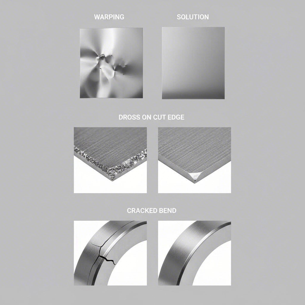
Even with perfect material selection and optimized process parameters, fabrication problems happen. The difference between a struggling shop and a profitable operation often comes down to how quickly teams diagnose issues and implement effective solutions. Whether you're dealing with warped panels, cracked bends, or inconsistent cuts, understanding root causes accelerates your path to resolution.
According to Smart Sheet Metal, warping and distortion pose significant challenges that compromise the integrity and functionality of fabricated products. Let's break down the most common problems by category and explore actionable fixes.
Preventing Warping and Distortion During Fabrication
Warping transforms flat, precise parts into unusable scrap. The problem stems from uneven thermal or mechanical stresses that pull the material out of shape—and certain materials prove more susceptible than others.
Common causes of warping:
- Rapid or uneven heating: Welding, laser cutting, and thermal processes introduce localized heat that expands material unevenly. When one area cools faster than another, internal stresses warp the part.
- Thin gauge selection: Thinner materials (20-gauge and lighter) lack the mass to resist thermal distortion. According to Accurl, thinner materials cut more easily but are prone to warping if laser power is too high or cutting speed too slow.
- Inadequate fixturing: Parts that move during fabrication accumulate stress unevenly, leading to distortion after release.
- Material properties: High thermal conductivity materials like aluminum spread heat rapidly, while low-conductivity materials like stainless steel concentrate heat—each requiring different management approaches.
Solutions that work:
- Implement controlled cooling techniques using fixtures or gradual ambient temperature reduction
- Use stitch welding patterns rather than continuous beads to distribute heat input
- Select thicker gauges when distortion tolerance is tight
- Consider stress-relieving heat treatment for critical components after welding
- Upgrade fixturing to provide uniform support and controlled clamping pressure
Solving Surface Finish Defects
Surface defects range from minor cosmetic issues to functional failures. Scratches, dross buildup, and discoloration can all render parts unacceptable—particularly for visible or anodized aluminum components where surface quality directly impacts the final appearance.
Cutting-related surface issues:
- Dross formation: To define dross simply, it's the resolidified metal that adheres to cut edges. Dross occurs when cutting parameters don't fully eject molten material from the kerf. Lower assist gas pressure or incorrect focus position commonly cause this defect.
- Burrs: Sharp edges remaining after cutting or punching indicate worn tooling, incorrect clearances, or improper cutting speed.
- Heat-affected zones: Discoloration around cuts—particularly visible on stainless steel—results from excessive heat input oxidizing the surface.
Effective remedies:
- Optimize cutting speed and power settings for each material and thickness combination
- Increase assist gas pressure to blow molten material clear of the cut
- Replace worn punches and dies before edge quality degrades
- For copper and oxidation concerns, use Nitrogen assist gas to prevent oxidation and discoloration on reactive or stainless metals
- Consider anodizing aluminum parts post-fabrication to create a uniform, protective surface that masks minor cutting marks
Addressing Dimensional Accuracy Issues
When parts don't fit together or meet specification, the root cause typically traces to bending problems, welding distortion, or cutting inconsistencies. According to JLC CNC, most sheet metal bending defects don't need expensive fixes—they just need better setup, smarter design, and a bit of prevention.
Bending problems:
- Springback: Material returning partially toward its original shape after bending. High-tensile materials like stainless steel and aluminum exhibit more springback than mild steel.
- Cracking: Fractures along the bend line indicate bend radius too tight, wrong grain orientation, or insufficient material ductility.
- Wrinkling: Compression on the inside of bends causes material bunching, particularly on long unsupported flanges.
Welding defects:
- Burn-through: Excessive heat melts completely through thin material. Common on gauges lighter than 20 when heat input isn't reduced appropriately.
- Warping: Heat concentration pulls material out of plane, especially problematic on stainless steel and aluminum.
- Porosity: Gas pockets trapped in welds compromise strength. Contaminated surfaces, insufficient shielding gas, or moisture cause this defect.
When to consider material substitution:
Sometimes the most effective solution involves changing materials rather than fighting process limitations. Consider substitution when:
- Cracking persists despite increased bend radii—switch to a more ductile alloy or temper
- Welding distortion remains uncontrollable—evaluate thicker gauges or materials with lower thermal expansion
- Surface finish requirements exceed process capability—materials that accept powder coat finishes hide minor fabrication marks effectively
- Corrosion failures occur in service—upgrading from carbon steel to galvanized or stainless eliminates the root cause
Troubleshooting fabrication issues requires systematic thinking: identify the defect, trace it to material properties or process parameters, and implement targeted solutions. With these diagnostic skills in place, you're ready to evaluate fabrication partners who can deliver consistent, defect-free results.
Choosing the Right Sheet Metal Fabrication Partner
You've defined your material requirements, optimized your design for manufacturability, and understand the fabrication processes your project demands. Now comes a decision that can make or break your project timeline and quality outcomes: selecting the right fabrication partner. When you search for metal fabricators near me or sheet metal fabrication near me, dozens of options may appear—but how do you separate capable partners from shops that will struggle with your requirements?
The lowest quote rarely represents the best value. According to Atscott MFG, true value lies in the fabricator's capabilities, reliability, and ability to meet your project requirements from start to finish. Let's examine the criteria that separate exceptional fabrication partners from the rest.
Essential Capabilities to Look for in a Fabrication Partner
Before contacting metal fabrication companies near me, clarify your project requirements—then evaluate whether potential partners can actually deliver. A detailed project scope allows you to compare fabricators based on relevant experience and capabilities rather than just price.
When evaluating sheet metal fabrication shops near me, assess these critical capability areas:
- Equipment capabilities: Verify the shop has necessary equipment—CNC machinery, press brakes, automated welders, or laser cutters—and staff trained to operate them. A shop with a 4kW fiber laser can't efficiently cut 20mm stainless steel if your project requires it.
- Material inventory and expertise: Not every shop works with all metals. Whether your project uses carbon steel, stainless steel, aluminum, or specialty alloys, confirm the fabricator specializes in those materials and maintains adequate inventory to prevent delays.
- Full-service capabilities: If you want a one-stop shop, choose a fabricator offering design, engineering, fabrication, assembly, and installation under one roof. Coordinating multiple vendors adds complexity and risk.
- Production volume flexibility: Some shops excel at prototype quantities but struggle with high-volume production. Others focus on mass production and can't cost-effectively handle small runs. Match the fabricator's sweet spot to your volume requirements.
- Finishing services: Evaluate whether powder coating services, anodizing, plating, or other finishing operations are available in-house or require outsourcing—which adds lead time and handling.
A skilled project manager or representative should walk you through your fabrication process with confidence and clarity. If they can't answer detailed questions about how they'll handle your specific material and design requirements, that's a warning sign.
Certification Standards That Ensure Quality
Certifications serve as objective evidence that a fabricator has implemented systems to consistently deliver quality products. According to Northstar Metal Products, certifications provide assurance that products and services meet recognized standards—particularly critical in industries where precision and safety are paramount.
Key certifications to verify when evaluating custom metal fabricators:
- ISO 9001:2015: Demonstrates the company has implemented an effective quality management system. This ensures products are manufactured to consistent standards with proper procedures for monitoring and continuous improvement.
- IATF 16949: The automotive industry's quality management system. Mandatory for suppliers in OEM and Tier-1 automotive supply chains. If your project involves automotive components, this certification is non-negotiable.
- AWS Certified Welding Fabricator: Signifies demonstrated proficiency in welding techniques, ensuring the integrity and durability of welded structures.
- UL Certifications: For electrical enclosures and safety-critical applications, UL certification confirms products meet rigorous safety and performance standards.
- ASME Certification: Essential for pressure vessel components and critical industrial applications.
Beyond certifications, evaluate the fabricator's internal quality systems. A well-implemented quality management system establishes clear guidelines for every production stage—from new product introduction through final inspection and shipping. Ask about inspection capabilities, documentation practices, and how they handle non-conforming materials.
Evaluating Turnaround Time and Prototyping Support
In product development, speed often matters as much as quality. The ability to iterate quickly through design revisions can mean the difference between beating competitors to market or arriving too late to capture opportunity.
When evaluating a metal fabrication shop near me for product development work, prioritize these factors:
- Rapid prototyping capabilities: How quickly can they turn initial designs into physical parts? Leading fabricators offer 5-day rapid prototyping that compresses weeks of traditional development into days.
- Quote turnaround time: Slow quotes delay project decisions. Responsive fabricators provide quotes within 12-24 hours, keeping your development timeline on track.
- DFM support: Does the fabricator offer comprehensive Design for Manufacturability feedback? Early DFM input prevents costly redesigns later. Partners who invest in reviewing your designs before production add significant value.
- Engineering collaboration: The best partners function as extensions of your engineering team, suggesting material alternatives, process optimizations, and design improvements that reduce cost and improve quality.
For automotive applications specifically, Shaoyi (Ningbo) Metal Technology exemplifies these capabilities. Their IATF 16949 certification addresses automotive quality requirements, while 5-day rapid prototyping accelerates development cycles. Comprehensive DFM support helps optimize designs before production commitment, and 12-hour quote turnaround keeps projects moving. For chassis, suspension, and structural components, their specialized expertise in automotive stamping and precision assemblies provides the focused capability that general-purpose steel fabrication shops near me typically lack.
Before finalizing your choice, verify the fabricator's track record. Request references from similar projects, review their portfolio of completed work, and ask about their experience with your specific materials and industry requirements. A fabricator who has successfully completed projects matching your specifications brings valuable process knowledge that reduces risk and accelerates production.
With the right fabrication partner identified, you're positioned to execute your project successfully. The final step is synthesizing everything you've learned into a practical decision framework that guides material selection from concept through production.
Making the Right Sheet Metal Choice for Your Project
You've journeyed through materials, gauges, processes, DFM principles, industry requirements, troubleshooting strategies, and partner evaluation criteria. Now it's time to pull everything together into a practical framework you can apply to your next project—and every project after that.
The material-first approach we've emphasized isn't just a philosophy; it's a decision-making structure that eliminates costly trial-and-error. When you select the right sheet metal before choosing fabrication methods, you're building on a foundation that supports every downstream decision. According to Modus Advanced, material selection for manufacturability represents one of the most critical early-stage decisions in product development—cascading through every aspect of manufacturing from initial prototyping through high-volume production.
Your Material Selection Decision Framework
Think of this framework as your rapid sheet metal selection checklist. Work through each step sequentially, and you'll arrive at material choices that balance performance, manufacturability, and cost-effectiveness.
- Define application requirements first: What loads must your part withstand? What environmental conditions will it face? Does weight matter? Is corrosion resistance critical? These functional requirements establish your minimum performance thresholds before cost even enters the conversation.
- Match material properties to requirements: Using your requirements as filters, identify material candidates. Need high strength with low weight? Aluminum alloys or AHSS climb the list. Require corrosion resistance in harsh environments? Stainless 316 or hot-dip galvanized emerge as contenders. As Komaspec notes, understanding mechanical properties—strength by cost, strength by weight, ductility, and corrosion resistance—is critical to selecting the right material.
- Verify fabrication process compatibility: Your chosen material must work with available fabrication methods. Will it laser cut cleanly at required thicknesses? Can it bend to specified radii without cracking? Does it weld reliably with your preferred process? Materials that excel functionally but create manufacturing bottlenecks can significantly impact project timelines and budgets.
- Specify surface finish and post-processing needs: Will the part be visible or hidden? Does it require painting, powder coating, or anodizing? Surface finish requirements influence material choice—mill finish steel accepts paint differently than stainless, and anodized aluminum demands specific alloys.
- Evaluate partner capabilities against requirements: Finally, confirm your fabrication partner can execute. Do they stock your material? Can they achieve your tolerances? Do they hold required certifications? A perfect material choice means nothing if your fabricator can't work with it effectively.
Next Steps for Your Fabrication Project
With this framework in hand, you're equipped to specify custom metal parts that fabricate efficiently and perform reliably in service. But knowledge without action doesn't move projects forward.
Your immediate next steps depend on where you are in the development cycle:
- Early concept stage: Use this guide to narrow material candidates before design details are finalized. Early material decisions prevent expensive redesigns later.
- Design refinement: Apply DFM principles to your CAD models. Verify bend radii, hole placements, and relief cuts meet material-specific requirements before releasing drawings.
- Ready for prototyping: Seek fabrication partners who offer rapid sheet metal prototyping with comprehensive DFM feedback. The right partner validates both design and manufacturability simultaneously.
- Production planning: Confirm your fabricator's certifications, quality systems, and capacity align with your volume requirements and industry standards.
For custom fabrication projects—particularly those requiring automotive-grade quality—manufacturers like Shaoyi Metal Technology offer comprehensive support spanning rapid prototyping through mass production. Their IATF 16949 certification addresses the stringent quality requirements for chassis, suspension, and structural components. With 5-day rapid prototyping capabilities and comprehensive DFM support, they compress development timelines while ensuring designs transition smoothly to production.
Ready to move forward with your project? A 12-hour quote turnaround means you won't wait days for pricing decisions. Explore their automotive stamping and precision assembly capabilities to see how the material-first approach we've discussed translates into production-ready metal fab solutions.
The path from concept to finished part doesn't have to be complicated. Start with the right material, design for manufacturability, and partner with fabricators who understand your requirements. That's how you match materials to methods like a pro.
Frequently Asked Questions About Sheet Metal for Fabrication
1. What is the best metal for fabrication?
The best metal depends on your specific application requirements. Low-carbon steel offers excellent weldability and cost-effectiveness for structural applications. Aluminum provides superior strength-to-weight ratios for lightweight solutions. Stainless steel 304 delivers corrosion resistance for food processing and medical equipment, while 316 stainless handles harsh marine and chemical environments. For automotive components requiring IATF 16949 certification, Advanced High-Strength Steels (AHSS) balance crash safety with weight reduction.
2. How much does it cost to fabricate sheet metal?
Sheet metal fabrication costs typically range from $4 to $48 per square foot, with project averages around $1,581. Key cost factors include material type (stainless costs more than carbon steel), gauge thickness, complexity of bends and cuts, required tolerances, finishing requirements like powder coating, and production volume. Choosing standard gauge sizes, optimizing designs for manufacturability, and working with fabricators offering rapid prototyping and DFM support can significantly reduce overall project costs.
3. Which is thicker, 18 or 22 gauge sheet metal?
18 gauge is thicker than 22 gauge. The gauge system uses an inverse relationship where lower numbers indicate thicker material. For steel, 18 gauge measures 0.0478 inches (1.21 mm), while 22 gauge measures only 0.0299 inches (0.76 mm). This difference matters significantly for fabrication—thicker gauges require more bending force and welding power but provide greater structural strength and resist distortion better during thermal processes.
4. What fabrication processes work best with different sheet metals?
Carbon steel excels with virtually all processes including laser cutting, MIG welding, and bending. Stainless steel requires TIG welding for corrosion-critical applications and slower laser cutting speeds. Aluminum demands specialized TIG welding with AC current and exhibits more springback during bending (5-10 degrees versus 1-3 degrees for steel). Galvanized steel works well for punching and roll forming but requires proper ventilation during welding due to zinc fume concerns.
5. What certifications should a sheet metal fabrication partner have?
Essential certifications depend on your industry. ISO 9001:2015 demonstrates quality management system implementation for general manufacturing. IATF 16949 is mandatory for automotive supply chains covering chassis, suspension, and structural components. AWS Certified Welding Fabricator ensures weld integrity. UL certifications apply to electrical enclosures, while ASME certification covers pressure vessel components. Manufacturers like Shaoyi Metal Technology combine IATF 16949 certification with rapid prototyping capabilities and comprehensive DFM support for automotive applications.