 Small batches, high standards. Our rapid prototyping service makes validation faster and easier —

Sheetmetal Forming: Fix Defects, Cut Costs, and Choose Right

What Is Sheet Metal Forming and Why It Matters
Imagine transforming a flat, unassuming piece of metal into a complex car door panel or a precision aerospace component—without cutting away a single gram of material. That's exactly what sheet metal forming accomplishes every day in manufacturing facilities worldwide.
Sheet metal forming is a manufacturing process that shapes flat metal sheets into three-dimensional components by applying force to plastically deform the material, modifying its geometry without adding or removing any material.
So what is sheet metal exactly? It refers to thin, flat metal pieces typically ranging from extremely thin foil up to 6 mm (0.25 in) in thickness. Beyond this threshold, you're working with plate steel or structural steel. This versatile material serves as the foundation for everything from beverage cans to aircraft fuselages.
Understanding the forming definition helps clarify why this process dominates modern manufacturing. Unlike machining operations that cut away material or welding processes that join pieces together, forming and shaping techniques reshape existing material through controlled deformation.
The Science Behind Permanent Metal Deformation
How is metal formed into permanent new shapes? The answer lies in a phenomenon called plastic deformation. When you apply force to a metal sheet, it initially responds elastically—meaning it wants to spring back to its original shape. Push harder, and you'll cross what engineers call the yield point.
Beyond this critical threshold, something remarkable happens. The metal's internal crystalline structure permanently rearranges itself. The atoms shift into new positions and stay there, even after you remove the force. This is plastic deformation in action, and it's the fundamental principle behind every sheet metal forming operation.
Think of it like bending a paperclip. A gentle flex returns to normal, but bend it far enough and it holds that new shape. Metals behave similarly, though the forces involved are dramatically higher and the results far more precise.
Why Sheet Metal Forming Dominates Modern Manufacturing
You'll find sheet metal forming at the heart of countless industries for compelling reasons:
- Material efficiency: Unlike machining, no material is wasted during the forming process
- Structural integrity: Formed parts maintain continuous grain structure, enhancing strength
- Cost-effectiveness: High-volume production becomes remarkably economical once tooling is established
- Versatility: Aluminum, steel, brass, copper, titanium, and even precious metals can all be formed
According to Formlabs, sheet metal forming is the most cost-effective forming procedure today for manufacturing parts in large quantities. The process powers industries from automotive and aerospace to appliances, electronics, and construction.
In this comprehensive guide, you'll learn how to select the right forming technique for your application, match materials to processes, troubleshoot common defects, and make informed decisions that cut costs without sacrificing quality. Whether you're an engineer designing your first formed component or a procurement professional evaluating manufacturing options, you'll find actionable insights throughout.
Core Sheet Metal Forming Techniques Explained
Now that you understand the fundamentals of plastic deformation, let's explore the specific metal forming processes that transform flat sheets into functional components. Each technique in the metal forming process offers distinct advantages depending on your part geometry, production volume, and material requirements.
Think of these methods as tools in a toolbox—choosing the right one makes all the difference between an efficient, cost-effective production run and a frustrating exercise in trial and error.
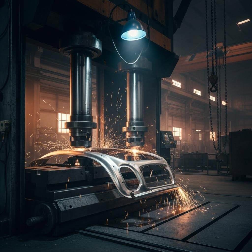
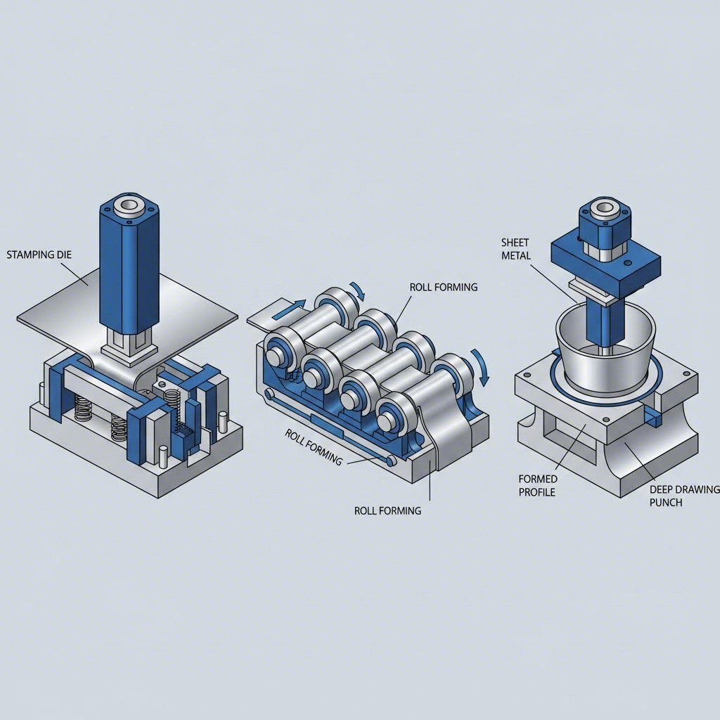
Stamping and Press Forming Fundamentals
Stamping is arguably the workhorse of the forming process in high-volume manufacturing. Picture a powerful press forcing sheet metal between precisely machined dies—that's stamping in its simplest form.
The process works by loading sheet metal blanks into a stamping press where a tool and die interface exerts tremendous force to reshape the material. According to Geomiq, modern stamping presses can handle capacities up to 400 tons and produce components as thin as 0.005 inches while maintaining tight tolerances.
What makes stamping so popular? Consider these advantages:
- Speed: High-speed presses can produce hundreds of parts per minute
- Consistency: Once tooling is perfected, every part comes out virtually identical
- Versatility: Operations can be combined into progressive dies for complex parts
- Cost efficiency: Per-part costs drop dramatically at high volumes
Steel forming through stamping dominates automotive manufacturing, producing everything from small brackets to large body panels. When you need thousands or millions of identical parts, stamping typically delivers the best economics.
Bending and Folding Operations
Bending represents one of the most straightforward types of forming, yet it requires careful attention to material behavior. The process applies force along a straight axis, causing the sheet to bend at a specific angle without removing any material.
A press brake—essentially a long, narrow press with interchangeable punch and die sets—performs most bending operations. The metal sheet sits between the upper punch and lower die, and as the punch descends, it forces the material into the die cavity. The depth of this penetration determines your final bend angle.
You'll encounter bending in virtually every fabrication shop because it excels at creating brackets, enclosures, channels, and architectural features. The process is particularly forgiving for low-to-medium volume production where dedicated stamping tooling isn't economical.
Deep Drawing for Complex Hollow Shapes
Ever wonder how manufacturers create seamless cups, cans, or kitchen sinks? Deep drawing sheet metal forming makes it possible by stretching material into cavity-shaped dies.
The process involves several key components working in harmony:
- Blank: A pre-cut piece of sheet metal, usually disc or rectangle shaped
- Blank holder: Secures the blank over the die cavity
- Punch: Forces the material into the die, typically powered by hydraulic systems
- Die: Contains the cavity that defines the final part shape
Deep drawing works best for parts where the depth exceeds half the diameter—think automotive fuel tanks, beverage cans, and cookware. The technique produces seamless components with excellent structural integrity, though it demands careful material selection and process control to avoid tearing or wrinkling.
Roll Forming for Continuous Profiles
When you need long, consistent profiles—roofing panels, structural beams, or storage shelving—sheet metal roll forming delivers unmatched efficiency. Unlike other processes that work on individual blanks, roll forming steel continuously shapes flat coils into complex cross-sectional geometries.
Imagine feeding a flat strip of metal through a series of roller stations, each progressively shaping the material closer to the final profile. By the time the metal exits the last station, it has transformed into a precisely formed shape ready for cutting to length.
Roll forming shines in applications requiring:
- Long production runs of identical profiles
- Complex cross-sections with multiple bends
- Tight dimensional tolerances over extended lengths
- High production speeds with minimal material waste
The construction, automotive, and appliance industries rely heavily on roll-formed components for their combination of strength, consistency, and cost-effectiveness.
Hydroforming: Fluid Pressure Precision
Hydroforming takes a dramatically different approach to shaping metal. Instead of mechanical force from punches and dies, this process uses highly pressurized fluid to press sheet metal into forming dies.
The procedure involves sealing a metal sheet within a hydraulic chamber and pumping fluid at high pressure. This uniform pressure distribution offers several unique advantages over conventional stamping, as noted by industry experts:
- Complex shapes: Fluid pressure creates smooth contours with minimal material thinning
- Weight reduction: Optimized material usage eliminates joining processes
- Consistent thickness: Uniform pressure maintains wall thickness throughout the part
Automotive manufacturers particularly value hydroforming for chassis components and body panels where complex geometries and lightweight construction matter most. However, the significant equipment investment makes it most economical for medium-to-high volume production.
Stretch Forming: Large Contoured Parts
Stretch forming excels where other techniques struggle—creating large, smoothly contoured parts with seamless surfaces. The process clamps sheet metal along its edges with gripping jaws, then stretches the material over a forming die.
What distinguishes stretch forming from other types of forming is how it handles material stress. By pre-stretching the metal before forming, the technique minimizes springback and produces exceptionally accurate contours. Aerospace manufacturers rely on this process for aircraft skin panels, while automotive producers use it for door and roof panels requiring precise curvature.
The process preserves material integrity better than many alternatives, making it ideal for applications where structural properties must remain uncompromised after forming.
Comparing Metal Forming Methods
Selecting the optimal forming process requires balancing multiple factors. The following comparison helps clarify which technique suits different manufacturing scenarios:
| Process | Description | Typical Materials | Part Complexity | Best Volume Range | Common Applications |
|---|---|---|---|---|---|
| Stamping | Press forces sheet between matched dies | Steel, aluminum, stainless | Medium to high | High volume (5,000–10,000+) | Automotive panels, brackets, electronics housings |
| Bending | Press brake forms angular bends | Most sheet metals | Low to medium | Low to medium | Enclosures, brackets, architectural elements |
| Deep Drawing | Punch stretches material into die cavity | Aluminum, steel, stainless | Medium to high | Medium to high | Cans, cookware, automotive tanks, sinks |
| Roll Forming | Continuous shaping through roller stations | Steel, aluminum, copper | Medium (profiles only) | High volume | Roofing, structural beams, shelving, trim |
| Hydroforming | Fluid pressure shapes material against die | Aluminum, steel, stainless | High | Medium to high | Chassis components, complex body panels |
| Stretch Forming | Material stretched over contoured die | Aluminum, titanium | Low to medium | Low to medium | Aircraft skins, automotive roof panels |
Each metal forming method represents a proven solution for specific manufacturing challenges. Your optimal choice depends on part geometry, material selection, production quantities, and cost constraints—factors we'll explore in greater depth as we examine material selection in the next section.
Material Selection Guide for Optimal Forming Results
Choosing the right technique is only half the battle—selecting the appropriate material determines whether your forming operation succeeds or fails. Different types of sheet metal material behave in dramatically different ways under forming pressure, and understanding these behaviors prevents costly mistakes before they happen.
Why does material selection matter so much? Consider this: the same punch and die setup that produces flawless parts in mild steel might tear aluminum or cause excessive springback in stainless steel. Each metal brings unique mechanical properties to the table, and matching those properties to your forming process is essential for consistent, high-quality results.
Key Material Properties That Affect Formability
Before diving into specific metals, you need to understand which properties influence forming behavior. Think of these as the vital signs that predict how a material will perform:
- Ductility: The ability to stretch without breaking—higher ductility means the material can handle more severe deformation
- Yield strength: The stress level where permanent deformation begins—lower yield strength generally means easier forming
- Work hardening rate: How quickly the material strengthens as it deforms—high work hardening can cause problems in multi-stage operations
- Elastic modulus: Determines springback behavior—higher values typically mean more elastic recovery after forming
- Minimum bend radius: The tightest bend achievable without cracking—varies significantly between materials and tempers
- Anisotropy: Directional property variations caused by rolling—affects formability depending on grain orientation
These properties aren't just academic concepts. They directly translate to real-world outcomes: whether your parts meet dimensional tolerances, whether you'll experience tearing during deep drawing, or whether your bent angles hold their shape.
Aluminum Forming Characteristics and Best Practices
Aluminum forming has surged in popularity thanks to the metal's exceptional strength-to-weight ratio. When you need lightweight components without sacrificing structural integrity, aluminum alloys often deliver the optimal solution.
Sounds straightforward? Here's where it gets interesting. According to Dahlstrom Roll Form, aluminum (specifically 5052-H32 alloy) is soft and not as strong as steel, yet offers good formability with a typical minimum inside bend radius of 1× material thickness—compared to 0.5× for many steels.
Key considerations when working with aluminum include:
- Springback tendency: Aluminum exhibits 7-10% springback, requiring overbending compensation in your tooling
- Surface sensitivity: Softer than steel, aluminum scratches easily and may require protective films during handling
- Thermal conductivity: High heat dissipation can affect warm forming operations
- Alloy selection matters: Different aluminum alloys (1100, 3003, 5052, 6061) offer varying formability characteristics
For deep drawing and complex geometries, aluminum's malleability makes it a flexible material that accommodates intricate shapes. However, thin gauges in complex bends can present springback challenges that require careful process compensation.
Working with Stainless Steel Challenges
Stainless steel offers unmatched corrosion resistance and aesthetic appeal, but these benefits come with forming challenges that catch many manufacturers off guard.
The numbers tell the story. According to Mech Power Tech, stainless steel exhibits 8-12% springback—significantly higher than mild steel's 5-7%. This elastic recovery demands precise compensation strategies and often more robust tooling.
Common stainless steel grades for forming operations include:
- 304 Stainless (annealed): The workhorse grade offering excellent corrosion resistance, though susceptible to pitting in warm chloride environments. Minimum bend radius of 0.5× thickness.
- 316 Stainless (annealed): Enhanced pitting resistance compared to 304, particularly valuable in marine or chemical environments. Similar formability characteristics.
- 430 Stainless: Lower cost than 300-series grades with good corrosion resistance, though slightly reduced compared to 304 or 316.
- UR52N Super Duplex: High strength that can't be increased by heat treatment, requiring a 2× thickness minimum bend radius—twice that of conventional stainless grades.
When forming stainless steel, expect higher tonnage requirements from your presses and accelerated tool wear. The material's work hardening characteristics mean that progressive die operations require careful planning to avoid excessive material strengthening between stages.
High-Strength Steel for Automotive Applications
The automotive industry's relentless pursuit of lighter, safer vehicles has driven demand for high-strength steel sheet metal types that offer superior crash performance with reduced weight. But these advanced materials present formability challenges that require specialized approaches.
High-strength steels encompass several categories:
- High-Strength Low-Alloy (HSLA): Yield strengths of 250-550 MPa with reasonable formability
- Dual-Phase (DP) Steels: Combine high strength with improved ductility through mixed microstructures
- Transformation-Induced Plasticity (TRIP) Steels: Exceptional energy absorption for crash components
- Martensitic Steels: Highest strength but most challenging formability
These materials require significantly higher forming forces and exhibit pronounced springback behavior. Successful forming often demands advanced simulation during the design phase, specialized tooling geometries, and sometimes hot forming techniques to achieve desired shapes.
Mild steel remains the cost-effective, predictable choice for applications where extreme strength isn't required. Cold rolled carbon commercial steel (CS-B) offers good formability with a minimum bend radius of 0.5× thickness, low cost, and consistent behavior that simplifies process development.
Material Thickness and Gauge Considerations
Material thickness—often expressed in gauge numbers—profoundly affects process selection and forming outcomes. Thicker materials require greater forming forces and typically exhibit different springback characteristics than thinner sheets.
Here's what you need to know about different types of sheet metal thickness:
- Thin gauges (less than 0.5mm): Prone to wrinkling in deep drawing, may require specialized blank holders
- Medium gauges (0.5-2mm): Most versatile range for conventional forming operations
- Heavy gauges (over 2mm): Approach plate territory, requiring higher tonnage equipment and potentially hot forming
The relationship between bend radius and material thickness is particularly critical. Most steel sheet metal material allows minimum inside bend radii of 0.5× to 1× material thickness, while aluminum typically requires 1× thickness and super duplex stainless needs 2× thickness to avoid cracking.
Understanding these types of metal sheets and their behaviors enables informed decisions that prevent production problems. When you match material properties to your forming process requirements, you set the stage for efficient production and consistently high-quality parts—a foundation that becomes even more valuable when we explore the equipment and tooling needed to execute these processes effectively.
Essential Equipment and Machinery Requirements
You've selected your forming technique and matched it to the right material—but what about the metal forming machines that make it all happen? Understanding equipment requirements separates successful production runs from costly trial-and-error experiments.
Whether you're specifying new metal forming equipment or evaluating existing capabilities, knowing the differences between press types, tonnage calculations, and tooling fundamentals empowers better manufacturing decisions.
Press Types and Their Forming Applications
Walk into any metal forming facility and you'll encounter three primary press categories, each with distinct operating characteristics. Choosing the right sheet metal forming machine depends on your specific production requirements.
Mechanical Presses
When speed matters most, mechanical presses deliver. These machines use a flywheel to store energy, releasing it through a crankshaft mechanism to generate forming force. According to Eigen Engineering, mechanical presses excel in high-volume stamping operations where consistent cycle times drive productivity.
Advantages of mechanical presses include:
- High production speeds: Capable of hundreds of strokes per minute
- Consistent energy delivery: Flywheel provides repeatable force application
- Lower operating costs: Simpler systems with reduced maintenance requirements
- Proven reliability: Decades of refinement in high-volume manufacturing
However, mechanical presses offer limited control at the bottom of the stroke—the critical moment when material deformation occurs. They're ideal for operations requiring consistent, repetitive cycles where flexibility takes a backseat to volume.
Hydraulic Presses
Need versatility and raw power? Hydraulic presses use pressurized fluid to generate force, offering capabilities that mechanical systems simply can't match. When working with heavier or high-tensile materials, hydraulic metal forming machinery often becomes the preferred choice.
Key advantages include:
- Full tonnage throughout stroke: Constant force application regardless of ram position
- Adjustable speed and pressure: Fine-tune parameters for different materials and geometries
- Deep drawing capability: Excellent for complex hollow shapes requiring controlled material flow
- Overload protection: Hydraulic systems prevent damage from excessive force
Hydraulic presses run slower than mechanical alternatives, but their consistency and adaptability prove invaluable for complex stamped metal parts where precision trumps speed.
Servo-Driven Presses
Servo presses represent the newest evolution in metal forming machinery, combining the speed of mechanical systems with the programmability of modern control technology. These machines use servo motors to drive the ram, enabling unprecedented control over speed, position, and force throughout each stroke.
Servo press benefits include:
- Programmable motion profiles: Customize speed and dwell time for optimal forming
- Energy efficiency: Motors consume power only when working
- Reduced noise: Quieter operation compared to mechanical presses
- Quick changeover: Adjust parameters through software rather than mechanical modifications
For jobs requiring exceptional accuracy—electronics components, medical devices, or high-end automotive parts—servo presses justify their higher upfront investment through reduced scrap and improved part quality.
Understanding Tonnage Requirements
Selecting the right press capacity isn't guesswork—it's calculated science. Undersize your equipment and you'll damage tooling or produce defective parts. Oversize dramatically and you're wasting capital investment.
According to industry expert Steve Benson writing for The Fabricator, calculating press tonnage involves multiple considerations beyond simply matching machine rating to job requirements.
Key tonnage calculation factors include:
- Material type and thickness: High-strength steels require significantly more force than mild steel
- Bend length: Longer bends distribute force across greater distances
- Die opening width: Wider V-openings reduce required tonnage
- Centerline loading: Most presses achieve rated capacity when load is centered—off-center work reduces safe capacity
A critical concept is the centerline load limit. Press brakes are designed for full-tonnage loads applied over approximately 60 percent of the distance between side frames. Exceeding this limit risks permanent damage to the bed and ram through excessive deflection.
For example, a 100-ton press brake with 10 feet between side frames calculates as:
Centerline load limit = 100 tons ÷ (120 inches × 0.60) = 1.39 tons per inch
Never exceed your machine's centerline load limit—doing so causes permanent deflection damage that compromises accuracy on every subsequent job.
Tooling Fundamentals for Precision Results
Even the most sophisticated press produces only what its tooling allows. Tools for forming sheet metal—dies, punches, and blank holders—translate press force into precise part geometry.
Punches attach to the press ram and apply direct force to the workpiece. Their geometry determines bend angles, draw depths, and forming contours. Modern precision-ground punches achieve hardness around 70 HRC, but this hardness comes with a warning: exceed load limits on these metalforming tools and they'll throw dangerous shrapnel rather than simply deforming like softer alternatives.
Dies provide the cavity or surface against which material forms. Die design directly impacts part quality, with considerations including:
- Surface finish requirements
- Draft angles for part ejection
- Material flow paths during deep drawing
- Wear resistance for production longevity
Blank holders control material flow in deep drawing operations. Too much pressure causes tearing; too little allows wrinkling. This forming tool sheet metal component requires precise calibration based on material properties and draw depth.
The land area—where tooling shoulders contact the press bed and ram—determines sinking tonnage limits. Larger shoulder widths distribute load over greater areas, allowing higher tonnage before tooling embeds into machine surfaces.
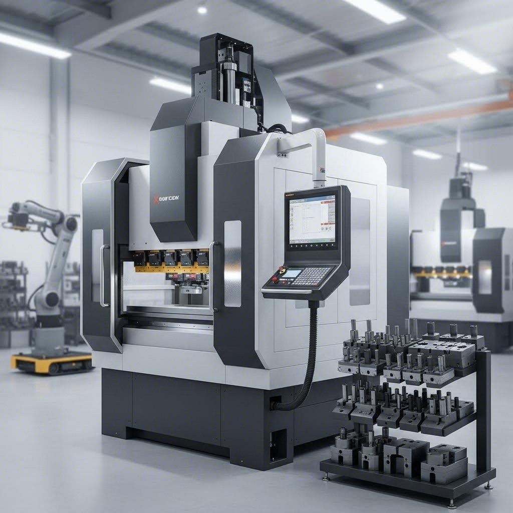
CNC Integration in Modern Forming Operations
Today's CNC forming technology transforms sheet metal operations from manual craft to precision manufacturing. Computer numerical control brings repeatability, flexibility, and documentation capabilities that manual operations simply cannot match.
Modern CNC press brakes offer:
- Programmable back gauges: Automatic positioning for consistent bend locations
- Angle measurement systems: Real-time feedback compensates for material variations
- Recipe storage: Save and recall complete job setups instantly
- Bend sequence optimization: Software calculates efficient forming order to avoid collisions
Automated forming systems extend beyond individual machines to include robotic material handling, automatic tool changers, and integrated quality inspection. These systems reduce labor requirements while improving consistency across production runs.
For high-mix, low-volume production, CNC forming dramatically reduces setup time between jobs. For high-volume operations, automation minimizes operator fatigue and variation while maintaining consistent output quality.
Equipment Considerations by Production Scenario
Matching equipment to your specific production needs ensures optimal return on investment. Consider these guidelines:
- Prototype and low-volume (under 1,000 parts): CNC press brakes with quick-change tooling offer flexibility without dedicated tooling investment
- Medium-volume (1,000-50,000 parts): Hydraulic or servo presses with application-specific tooling balance setup costs against per-part efficiency
- High-volume (50,000+ parts): Mechanical presses with progressive dies or transfer systems maximize throughput and minimize per-part costs
- Complex geometries: Hydraulic presses or hydroforming equipment provide controlled material flow
- Precision-critical applications: Servo-driven presses offer programmable motion profiles for optimal forming
Your equipment selection directly impacts what defects you'll encounter and how easily you can correct them—challenges we'll address comprehensively in the next section on troubleshooting common forming problems.
Troubleshooting Common Forming Defects
Even with the right equipment, materials, and techniques, defects happen. The difference between struggling manufacturers and successful ones lies in understanding why problems occur and how to fix them quickly.
When forming metal sheet, you're pushing material beyond its elastic limits—and that's precisely where things can go wrong. Whether you're dealing with dimensional inaccuracies, surface imperfections, or outright material failures, each defect traces back to identifiable root causes with proven solutions.
Let's break down the four major sheet metal fabrication techniques challenges you'll encounter and exactly how to solve them.
Preventing and Correcting Springback Issues
Ever bend a part to exactly 90 degrees, release it from the press, and watch it spring back to 87 degrees? That's springback—and it's arguably the most frustrating defect in press forming operations.
Springback occurs because metal deformation involves both plastic (permanent) and elastic (temporary) components. When you release forming pressure, the elastic portion recovers, partially reversing your carefully calculated bend. According to LYAH Machining, this defect becomes particularly challenging when working with high-strength or thick materials.
What causes excessive springback?
- Material properties: Higher yield strength and elastic modulus increase elastic recovery
- Bend radius: Larger radii relative to thickness produce more springback
- Material thickness: Thinner materials typically exhibit greater proportional recovery
- Forming temperature: Cold forming produces more springback than warm forming
Prevention strategies:
- Overbending: Calculate the expected springback angle and bend beyond your target—compensating tooling builds this correction into die geometry
- Bottoming or coining: Apply additional force at the bottom of the stroke to plastically deform the bend zone more completely
- Material selection: When possible, choose alloys with lower yield strength for critical bends
- Reduced bend radii: Tighter bends (within material limits) reduce elastic recovery
For sheet metal stretching operations, pre-stretching the material before forming minimizes springback by ensuring the entire cross-section undergoes plastic deformation rather than just the outer fibers.
Eliminating Wrinkling in Deep Drawn Parts
Wrinkling appears as wave-like formations, typically on the inside of bends or in the flange areas of deep drawn components. While it might seem like a minor cosmetic issue, wrinkling compromises structural integrity and often makes parts unusable.
When drawing metal sheet into cavity dies, the material in the flange area experiences compressive forces as it's pulled inward. If these compressive stresses exceed the material's ability to resist buckling, wrinkles form. As noted by Karkhana.io, this wrinkle defect in sheet metal arises due to inadequate die design, compression, or poor blank holding.
Root causes of wrinkling:
- Insufficient blank holder pressure: Material flows too freely into the die cavity
- Excessive blank size: Too much material in the flange creates compressive instability
- Thin material gauges: Thin sheets buckle more easily under compression
- Poor die clearance: Incorrect spacing between punch and die allows material to fold
Corrective actions:
- Increase blank holder force: Apply more pressure to resist buckling—but balance against tearing risk
- Optimize blank geometry: Use correctly sized blanks that minimize excess flange material
- Add draw beads: These raised features in the die control material flow and increase restraint
- Adjust die clearance: Proper clearance (typically 10-15% greater than material thickness) prevents folding
In sheet metal pressings where wrinkling persists, consider annealing the material between drawing stages to restore ductility and reduce residual stresses that contribute to buckling.
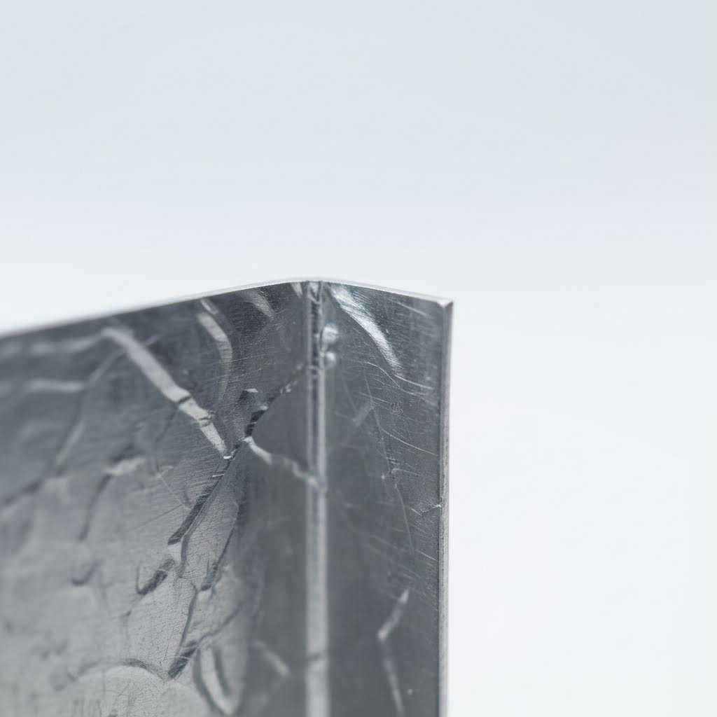
Avoiding Tearing and Cracking Failures
Tearing and cracking represent the most severe forming operation failures—material literally fracturing under excessive strain. Unlike springback or wrinkling, which might allow salvage operations, torn or cracked parts are scrap.
Tearing occurs when tensile stresses exceed the material's ultimate strength, typically at areas of maximum stretch. According to LYAH Machining, cracking is especially common in brittle materials or those with poor ductility, such as cast iron or hard steel alloys.
Why does tearing happen?
- Excessive blank holder pressure: Material can't flow into the die, forcing excessive stretch
- Sharp punch radii: Stress concentrations at small radii initiate fractures
- Insufficient material ductility: Work-hardened or low-ductility alloys fail prematurely
- Improper draw depth: Attempting too deep a draw in a single operation overstresses material
Cracking versus tearing: While tearing typically occurs during forming, cracking may appear at stress concentrations—sharp corners, punched holes near bends, or areas with grain direction issues—sometimes days after forming as residual stresses redistribute.
Prevention and correction:
- Increase punch and die radii: Larger radii distribute stress over greater areas—the minimum bend radius rule (0.5× to 2× material thickness depending on material) exists for good reason
- Reduce blank holder force: Allow more material flow while maintaining wrinkle control
- Use intermediate annealing: Restore ductility between progressive drawing stages
- Select appropriate materials: Choose alloys with higher elongation values for severe forming
- Consider warm forming: Elevated temperatures improve ductility in challenging applications
The Critical Bend Radius-Thickness Relationship
Understanding the relationship between bend radius and material thickness prevents most tearing and cracking failures before they occur. This isn't just theoretical—it's the foundation of defect-free forming.
When you bend sheet metal, the outer surface stretches while the inner surface compresses. The neutral axis—where neither stretching nor compression occurs—lies somewhere between. Tighter bends create more severe outer-surface stretching, eventually exceeding material limits.
General minimum bend radius guidelines:
- Mild steel: 0.5× material thickness
- Aluminum (5052-H32): 1× material thickness
- Stainless steel (304/316): 0.5× material thickness (annealed)
- High-strength steel: 1× to 2× material thickness depending on grade
- Super duplex stainless: 2× material thickness minimum
Grain direction also matters significantly. Bends parallel to the rolling direction (with the grain) tolerate tighter radii than bends perpendicular to grain. For critical applications, specify grain orientation on drawings and verify during incoming inspection.
Quick Reference: Defects, Causes, and Solutions
When troubleshooting forming operation problems, this comprehensive reference helps identify issues and implement corrections quickly:
| Defect | Root Causes | Prevention Methods | Corrective Solutions |
|---|---|---|---|
| Springback | Elastic recovery after forming; high yield strength materials; large bend radii relative to thickness | Overbend compensation in tooling; bottoming/coining operations; material selection for lower yield strength | Adjust die geometry; increase forming force; add pre-stretching step; consider warm forming |
| Wrinkling | Insufficient blank holder pressure; excess flange material; thin gauges; poor die clearance | Optimize blank holder force; correct blank sizing; add draw beads; maintain proper die clearance | Increase restraint force; reduce blank size; add intermediate annealing; redesign die with draw beads |
| Tearing | Excessive tensile strain; too-tight punch radii; excessive blank holder pressure; poor material ductility | Use adequate punch/die radii; balance blank holder force; select high-elongation materials | Increase radii; reduce restraint; add drawing stages; consider material substitution |
| Cracking | Stress concentrations at sharp features; work hardening; grain direction issues; delayed failure from residual stress | Eliminate sharp corners; maintain minimum bend radii; orient bends with grain direction; use stress relief | Redesign features; add relief cuts; intermediate annealing; stress-relief heat treatment |
Successful troubleshooting requires systematic analysis. When defects appear, resist the urge to make multiple changes simultaneously—adjust one variable, evaluate results, then proceed. Document what works so your team builds institutional knowledge that prevents future problems.
Of course, the best troubleshooting happens before production begins. In the next section, we'll explore design for manufacturing principles that prevent these defects from occurring in the first place—saving time, material, and frustration throughout your production lifecycle.
Design for Manufacturing Best Practices
What if you could eliminate 80% of your forming defects before cutting a single blank? That's the power of Design for Manufacturability—or DFM—applied to sheet metal engineering. The decisions you make at the CAD workstation determine whether your production runs smoothly or becomes an expensive lesson in redesign.
Here's the uncomfortable truth: most sheet metal forming problems aren't caused by equipment failures or operator errors. They're designed into the part from the beginning. A hole placed too close to a bend. A radius too tight for the material. Tolerances that ignore real-world manufacturing capabilities. Each oversight translates directly into scrapped parts, delayed schedules, and budget overruns.
The sheet metal manufacturing process rewards engineers who understand fabrication constraints before committing to tooling. Let's explore the critical DFM rules that separate cost-effective designs from manufacturing nightmares.
Critical Bend Radius and Thickness Relationships
Remember our discussion of tearing and cracking? Those failures trace back to one fundamental relationship: bend radius versus material thickness. Get this wrong, and no amount of process adjustment will save your parts.
According to Norck's design guidelines, the inside curve of your bend should at least match the thickness of the metal. Think of it like folding cardboard—bend too sharply and the outer edge cracks or develops "crazing."
But here's the practical benefit that often gets overlooked: if you design all your bends to use the same radius, manufacturers can use a single tool for every fold. This saves setup time and reduces your labor costs significantly.
Essential bend radius guidelines for your designs:
- Minimum inside radius: Equal to or greater than material thickness (1× t) for most materials
- Standardize radii: Use consistent bend radii throughout your part to minimize tool changes
- Account for springback: Allow 2-3 degrees of angular tolerance for production variation
- Consider grain direction: Bends perpendicular to rolling direction tolerate tighter radii than parallel bends
The K-factor—the ratio between the neutral axis location and material thickness—becomes critical for calculating accurate flat patterns. According to Geomiq's design guide, K-factor values typically range from 0.25 to 0.50, depending on material, bending operation, and bend angle. Getting this value correct in your CAD software prevents costly dimensional errors when parts reach the shop floor.
Strategic Feature Placement for Manufacturability
Where you place holes, slots, and cutouts matters just as much as bend geometry. Poor feature placement creates stress concentrations, distortion, and assembly problems that compound throughout production.
Hole Placement Near Bends
Place a hole too close to a bend line and watch it stretch into an oval during forming. Suddenly, screws don't fit and pins won't align. The fix is simple: maintain adequate clearance.
The rule from industry best practices: keep holes a minimum of two times the material thickness from any bend location. This ensures your component fits together flawlessly the first time, eliminating costly reworks or discarded parts.
Relief Cuts for Complex Geometries
When you bend metal alongside a flat edge, the material tries to separate at the corner. To prevent tearing, add a bend relief—a small rectangular or circular cutout at the end of your bend lines.
This simple feature guarantees a clean, professional finish that won't break under stress. Your product becomes more resilient for end users, and your reject rates plummet.
Minimum Flange Length
A flange is the portion of metal being bent up. Press brake tooling needs enough surface area to grip the material for folding. If your flange is too short, it's like trying to fold a tiny sliver of paper with giant fingers—the machine simply can't execute the bend properly.
Make sure your flange is at least four times as long as the metal is thick. Longer flanges allow manufacturers to use standard tools. Short, "illegal" flanges require custom, expensive molds that can double your production costs.
Narrow Cutout Considerations
Laser cutters use intense heat. If your design includes very long, thin "fingers" or narrow slots, heat can warp or twist the metal like a potato chip. Keep any narrow cutouts at least 1.5 times wider than the material thickness to maintain flatness and accuracy.
Grain Direction: The Hidden Variable
Metal sheets are manufactured by rolling, which creates a "grain" similar to wood. This anisotropic property—where material behaves differently depending on direction—significantly affects formability.
Metal is much more likely to crack if you try to bend it parallel to the grain direction. Design your parts so bends occur across the grain, not with it. This "hidden" rule prevents parts from failing or cracking months after delivery—a quality issue that damages customer relationships and brand reputation.
For critical applications, specify grain orientation on your drawings and verify compliance during incoming material inspection.
Tolerance Specifications That Balance Quality and Cost
Tolerances communicate your quality requirements to manufacturers—but overly tight specifications drive costs through the roof without improving functional performance.
Metal is slightly elastic. When formed to 90 degrees and released, it naturally wants to spring back slightly. Demanding exactly 90.00 degrees when 89-91 degrees works perfectly fine increases inspection time, raises rejection rates, and inflates your per-part costs.
Key tolerance considerations for the sheet metal fabrication process:
- Angular tolerances: Standard sheet metal achieves ±1-2 degrees on bends—specify tighter only when functionally necessary
- Hole diameters: Use standard "off-the-shelf" hole sizes (5mm, 6mm, 1/4 inch) whenever possible. Custom dimensions require special tooling that delays production and adds cost
- Feature locations: ±0.5mm is achievable for most punched or laser-cut features; tighter tolerances require secondary operations
- Flatness: Specify only for mating surfaces; general flatness callouts across entire parts create unnecessary inspection burden
According to Norck, being flexible with tolerances where precision isn't necessary keeps your project on budget while still meeting functional requirements.
DFM Rules Checklist for Sheet Metal Design
Before releasing any design for tooling, verify compliance with these essential sheet metal fabrication processes guidelines:
- Bend radii: Inside radius equals or exceeds material thickness; consistent radii throughout part
- Hole placement: Minimum 2× material thickness from bend lines
- Bend reliefs: Added at corners where bends meet edges
- Minimum flange length: At least 4× material thickness
- Narrow features: Width exceeds 1.5× material thickness
- Grain direction: Bends oriented perpendicular to rolling direction when possible
- Tolerances: Specified only where functionally required; standard tolerances used elsewhere
- Standard hole sizes: Off-the-shelf dimensions specified for punched features
The Business Case for Early DFM Review
Why does DFM review before tooling commitment matter so much? Consider the cost multiplier effect: changes made during design cost 1× to implement. The same changes during tooling development cost 10×. After production starts? You're looking at 100× or more when you factor in scrapped tooling, delayed shipments, and expedited redesign.
Early DFM collaboration between design and manufacturing teams catches issues when fixes cost pennies instead of dollars. Many leading fabricators now offer DFM feedback as part of their quoting process, identifying potential problems before you've invested in production tooling.
The sheet metal process rewards engineers who design with fabrication in mind from day one. By following these guidelines, you're not just avoiding defects—you're building parts that are faster to produce, less expensive to manufacture, and more reliable in service. That foundation of manufacturable design becomes even more valuable when we examine how production volume affects process selection and overall project economics.
Cost Analysis and Process Selection Framework
You've mastered DFM principles and know how to prevent defects—but how do you choose between forming processes when budget constraints enter the equation? The economic reality of sheet metal production often determines success or failure long before the first part hits the press.
Here's what many engineers discover too late: selecting a forming process based solely on technical capability ignores the financial factors that make or break project profitability. A hydroformed part might be technically superior, but if your volumes don't justify the tooling investment, you've just designed yourself into a cost trap.
Let's break down the economic framework that guides smart process selection decisions.
Volume Thresholds for Process Selection
Production volume is the single most influential factor in forming process economics. The relationship isn't linear—it follows dramatic step functions where certain processes become economically viable only after crossing specific thresholds.
Consider stamping: according to industry cost analysis, stamping dies typically require upfront investments of $5,000–$50,000 depending on part complexity. That sounds expensive until you realize per-part costs can drop to under $0.50 for simple geometries at high volumes.
The math becomes compelling quickly:
- 10,000 parts: $50,000 tooling ÷ 10,000 = $5.00 per part just for tooling amortization
- 100,000 parts: $50,000 tooling ÷ 100,000 = $0.50 per part for tooling
- 1,000,000 parts: $50,000 tooling ÷ 1,000,000 = $0.05 per part for tooling
When does stamping beat alternatives? The crossover point typically falls between 10,000 and 50,000 parts, depending on part complexity and alternative process costs. Below these volumes, flexible processes like laser cutting with CNC bending often prove more economical despite higher per-part processing costs.
Roll forming follows similar economics but with different threshold characteristics. The process excels for continuous profiles needed in high volumes—roofing panels, structural channels, or shelving components. Initial tooling for roll forming can exceed stamping costs, but the continuous nature of production drives per-foot costs remarkably low for appropriate applications.
Hydroforming occupies a middle ground: higher tooling investment than stamping but lower than progressive die systems for complex geometries. The process becomes economical when part complexity would otherwise require multiple stamping operations or when weight reduction through optimized wall thickness justifies premium costs.
Tooling Investment Versus Per-Part Economics
Understanding the relationship between upfront investment and ongoing costs reveals why volume projections matter so critically. Different forming approaches distribute costs in fundamentally different ways.
The following comparison illustrates how process economics shift across production volumes:
| Forming Process | Typical Tooling Cost | Ideal Volume Range | Per-Part Cost Trajectory | Break-Even Considerations |
|---|---|---|---|---|
| Stamping | $5,000–$50,000+ | 10,000+ parts | $0.30–$1.50 at volume | High initial investment amortizes rapidly at scale |
| Progressive Die Stamping | $25,000–$150,000+ | 50,000+ parts | $0.10–$0.75 at volume | Highest efficiency for complex multi-feature parts |
| Laser Cutting + Bending | $0–$2,000 (fixtures) | 1–10,000 parts | $2–$10 per part | Minimal setup; ideal for prototypes and low volume |
| Roll Forming | $15,000–$100,000+ | 25,000+ linear feet | Very low per foot at volume | Continuous profiles only; exceptional at scale |
| Hydroforming | $10,000–$75,000 | 5,000–50,000 parts | $1–$5 per part | Justifies premium for complex hollow shapes |
| Deep Drawing | $8,000–$60,000 | 10,000+ parts | $0.50–$3 at volume | Optimal for cylindrical and cup-shaped geometries |
Material utilization rates add another economic dimension. Stamping operations with optimized nesting achieve 85–95% material yield, according to manufacturing cost studies. This efficiency compounds savings when working with expensive materials like stainless steel or aluminum alloys.
Secondary operations also factor into total cost calculations. A stamped part requiring extensive deburring, additional machining, or complex assembly may cost more overall than an alternative process producing a more finished component. Progressive die stamping often eliminates secondary operations entirely by combining multiple forming steps in a single press stroke.
Rapid Prototyping Before Production Commitment
The transition from concept to volume production represents one of the highest-risk phases in sheet metal manufacturing. Committing $50,000 to production tooling based solely on CAD models and simulations is a gamble that doesn't always pay off.
This is where rapid sheet metal prototyping proves its value. According to prototyping strategy research, a sheet metal prototype serves as a tangible verification of form and function under actual manufacturing conditions—something CAD models alone cannot provide.
What does metal prototyping reveal that simulations miss?
- Design oversights: Incorrect hole positions, missing clearances, wrong bend sequences, or features that cannot be formed as drawn become immediately apparent
- Manufacturability vulnerabilities: Building a prototype forces you through the exact processes needed for each feature, revealing whether tools can achieve required bends or if operations slow production
- Assembly validation: Physical prototypes confirm that mating parts actually fit together—a critical verification before tooling investment
- Material behavior: Real-world springback, surface finish, and forming limits become measurable rather than theoretical
Prototype sheet metal parts typically use flexible processes like laser cutting and CNC bending that require minimal tooling investment. These methods accommodate design iterations without the cost penalties associated with modifying production dies.
For automotive applications requiring IATF 16949-certified quality, manufacturers like Shaoyi offer 5-day rapid prototyping services that help validate designs before committing to production tooling. Their comprehensive DFM support during the prototype phase identifies manufacturability issues early, when corrections cost pennies instead of dollars.
The prototyping-to-production transition typically follows this sequence:
- Initial prototype: Validate basic geometry and fit using flexible processes
- Design refinement: Incorporate lessons learned from prototype evaluation
- Pilot production: Small batch (50–500 parts) using near-production processes
- Production tooling: Full investment in optimized dies and automation
- Volume production: High-speed manufacturing with amortized tooling costs
Each stage serves as a checkpoint. If the sheet metal prototype performs as expected, the design advances. If problems appear, changes remain relatively inexpensive compared to discovering issues after production tooling is complete.
Making the Right Process Decision
When evaluating forming processes for your specific application, consider these decision factors in order of importance:
- Projected lifetime volume: Your total production quantity over the product lifecycle determines which processes can amortize tooling costs effectively
- Part complexity: Simple bends favor flexible processes; complex multi-feature parts justify progressive die investment
- Material costs: Expensive materials magnify the importance of high material utilization rates
- Time to market: Metal rapid prototyping and flexible processes accelerate initial production; dedicated tooling takes longer but runs faster once operational
- Quality requirements: Certifications like IATF 16949 for automotive or AS9100 for aerospace may dictate supplier and process capabilities
- Secondary operations: Factor in all post-forming costs including deburring, machining, finishing, and assembly
Automotive OEMs save 20–30% in unit cost using progressive stamping versus CNC machining for structural brackets, according to manufacturing cost studies. That savings compounds across millions of vehicles—but only makes sense when volumes justify the tooling investment.
For low-volume sheet metal prototyping or production runs under a few thousand parts, the flexibility of laser cutting combined with press brake bending often delivers better overall economics despite higher per-part processing costs. No tooling investment means no financial penalty for design changes or product discontinuation.
The key insight? Match your process selection to your actual production reality, not aspirational volumes that may never materialize. Conservative volume projections protect against stranded tooling investments while preserving the option to upgrade processes as demand proves itself.
With cost frameworks established and process selection optimized, the final critical consideration is ensuring your chosen manufacturing approach meets required quality standards and maintains safe operations—topics we'll address comprehensively in the following section.

Quality Assurance and Safety Standards
You've selected the right process, optimized your design, and calculated the economics—but how do you ensure every part leaving your facility meets specifications? And equally important, how do you protect the operators running those powerful presses?
Quality control and safety represent two sides of the same coin in sheet metal processing. Cutting corners on either creates liability, wastes resources, and damages your reputation. Yet these critical topics remain surprisingly underaddressed in most manufacturing guidance. Let's change that.
Dimensional Inspection and Measurement Techniques
Every formed part tells a story through its dimensions. Precision sheet metal forming demands verification methods that catch deviations before defective sheet metal components reach customers.
What inspection approaches deliver reliable results?
- Coordinate Measuring Machines (CMMs): These automated systems probe parts at programmed points, comparing actual dimensions against CAD models. CMMs excel for complex geometries where multiple features must maintain tight relationships
- Optical comparators: Project magnified part profiles against reference overlays for quick visual verification of contours and edge conditions
- Go/no-go gauges: Simple, fast verification tools for critical dimensions—holes, slot widths, bend angles—that operators can use at the press
- Laser scanning: Captures complete surface geometry for comparison against nominal models, identifying warpage, springback, and subtle deformations
- Height gauges and calipers: Essential hand tools for in-process checks and first-article inspection
First-article inspection (FAI) establishes the baseline. Before production runs begin, thoroughly measure initial parts against all drawing specifications. Document results and retain samples for future reference. This investment in upfront verification prevents entire production lots from going out of tolerance.
Statistical Process Control (SPC) maintains quality throughout production runs. By tracking key dimensions on control charts, operators identify trends before parts drift out of specification. A dimension trending toward its upper limit signals the need for adjustment—preventing scrap rather than creating it.
Surface Quality Assessment
Beyond dimensions, surface condition determines whether parts meet functional and aesthetic requirements. Metal processing operations can introduce defects that compromise performance or appearance.
Common surface quality checkpoints include:
- Scratches and gouges: Often caused by debris in dies or improper material handling
- Orange peel texture: Indicates excessive stretching beyond material limits
- Die marks: Transfer from worn or damaged tooling surfaces
- Burrs: Sharp edges remaining from punching or shearing operations
- Galling: Material transfer between workpiece and tooling, creating surface irregularities
Visual inspection under consistent lighting conditions catches most surface defects. For critical applications, surface profilometers quantify roughness values (Ra, Rz) to verify finish requirements. Maintaining clean tooling and proper lubrication prevents most surface quality issues before they occur.
Material Testing for Formed Parts
The manufacturing of metal parts requires verification that incoming materials and finished components meet mechanical property requirements. Testing protocols vary based on application criticality and customer specifications.
Essential material verification includes:
- Tensile testing: Confirms yield strength, ultimate strength, and elongation values match material certifications
- Hardness testing: Verifies material condition and detects unintended work hardening from forming operations
- Chemical analysis: Ensures alloy composition matches specifications, particularly critical for stainless steels and specialty alloys
- Formability testing: Limiting Dome Height (LDH) and Erichsen tests evaluate material behavior under forming conditions
Material certifications from suppliers provide baseline data, but incoming inspection sampling catches lot-to-lot variations that could affect forming performance. Retain samples from each material lot to support traceability and root cause analysis if quality issues emerge.
Industry Certifications and Quality Standards
Industry certifications demonstrate that manufacturers maintain systematic approaches to quality—not just occasional good results. Understanding these standards helps you evaluate suppliers and ensure your quality requirements will be met.
IATF 16949 for Automotive Applications
The International Automotive Task Force developed IATF 16949 specifically for the automotive supply chain. According to industry standards analysis, IATF 16949 adds many requirements around process design and control, competence for specific individuals, statistical tools, and measurement system analysis to the baseline ISO 9001 framework.
Key IATF 16949 additions include:
- Advanced Product Quality Planning (APQP): Structured approach to product development
- Production Part Approval Process (PPAP): Formal validation before production begins
- Measurement System Analysis (MSA): Verification that inspection methods are capable
- Statistical Process Control (SPC): Ongoing monitoring of production processes
- Error-proofing requirements: Systematic prevention of defects
For automotive sheet metal components—chassis, suspension, and structural parts—IATF 16949 certification signals that a manufacturer maintains the rigorous quality systems these critical applications demand. Certified manufacturers like Shaoyi maintain these quality systems specifically for chassis, suspension, and structural components, demonstrating how certification translates to reliable production quality throughout the automotive supply chain.
AS9100 for Aerospace Applications
The aerospace industry developed AS9100 through the International Aerospace Quality Group. This standard addresses the unique demands of aircraft, space, and defense manufacturing where failure consequences are severe.
AS9100 emphasizes:
- Product safety: Formal processes to identify and control safety-critical characteristics
- Configuration management: Tracking exact specifications for each serialized part
- Counterfeit parts prevention: Controls ensuring only authentic materials enter production
- On-time delivery: Metrics and improvement processes for schedule performance
- Human factors: Recognition of how operator conditions affect process outcomes
When selecting suppliers for aerospace sheet metal components, AS9100 certification provides assurance that manufacturers understand and implement aerospace-specific quality requirements beyond general manufacturing standards.
Operational Safety Protocols
Press operations present serious hazards. The same forces that permanently deform metal can cause devastating injuries in seconds. According to press safety research, press brakes have numerous pinch points, particularly around the backgauge system and bending area, where severe injuries can occur if an operator's hands or fingers are caught.
Effective safety programs address three categories: machine safeguarding, operational procedures, and training.
Machine Safeguarding Requirements
Physical and electronic safeguards prevent operators from entering hazardous zones during machine operation:
- Light curtains: Create invisible barriers using infrared beams—if crossed, the machine stops automatically before injury can occur
- Two-hand controls: Require both hands to activate the press, ensuring hands are clear of danger zones during operation
- Fixed guards: Physical barriers preventing access to pinch points and moving components
- Interlocked guards: Connected to machine controls, preventing operation unless guards are in position
- Emergency stop buttons: Strategically placed for rapid shutdown access during incidents
- Presence sensing devices: Detect when operators enter hazard areas and halt operation
OSHA standards (29 CFR 1910.212) and ANSI B11.3 establish minimum safeguarding requirements. Compliance isn't optional—these regulations carry legal enforcement and penalty provisions.
Safe Operating Procedures
Beyond machine safeguards, operational protocols protect workers during routine activities:
- Lockout/tagout: Mandatory energy isolation procedures before any maintenance or die changes
- Material handling: Proper lifting techniques and equipment for heavy dies and sheet metal blanks
- Clear work areas: Organized environments prevent tripping hazards and ensure emergency access
- Personal protective equipment: Safety glasses, hearing protection, and appropriate gloves for material handling (never during press operation)
- Fatigue management: Scheduling and break policies that maintain operator alertness
Die changes present particular risks. Heavy tooling components require proper lifting equipment—not manual handling that invites back injuries and dropped loads. Establish formal procedures for every die change operation.
Training and Certification
Equipment and procedures only protect workers when properly implemented. Comprehensive training ensures operators understand both how to work safely and why each requirement exists:
- Initial qualification: Complete training covering mechanical principles, safety protocols, and machine operation before independent work
- Regulatory compliance: Specific instruction on OSHA requirements and company policies
- Hands-on practice: Supervised operation building practical skills before solo work
- Regular refresher courses: Periodic retraining maintaining awareness and updating skills
- Certification documentation: Records demonstrating training completion for each operator
Safety certifications like the Press Brake Safeguarding Certificate validate operator competency and demonstrate organizational commitment to safe operations.
Essential Quality and Safety Checkpoints
Implementing comprehensive quality and safety programs requires systematic attention to multiple areas. Use this checklist to evaluate your current practices:
- Dimensional inspection: First-article verification, in-process checks, and final inspection protocols defined and followed
- Surface quality: Visual inspection standards established with reference samples for acceptance criteria
- Material verification: Incoming inspection and lot traceability maintained
- Certification maintenance: Required industry certifications current and audit-ready
- Machine safeguarding: All presses equipped with appropriate guards, light curtains, or other protective devices
- Emergency stops: Accessible, tested, and clearly marked at all equipment
- Lockout/tagout: Written procedures and training records for all maintenance personnel
- Operator training: Documentation demonstrating qualification for each person operating equipment
- PPE compliance: Appropriate protection available and usage enforced
- Incident reporting: System for documenting and investigating near-misses and injuries
Quality and safety aren't destinations—they're ongoing commitments. Regular audits, management review, and continuous improvement processes keep these programs effective as operations evolve. With robust quality systems and comprehensive safety protocols in place, your sheet metal operations deliver consistent results while protecting your most valuable asset: your people.
Industry Applications and Moving Forward
Now that you understand the techniques, materials, equipment, and quality systems behind successful sheet metal work, let's explore where these capabilities create real-world impact. From the car you drive to the refrigerator in your kitchen, sheet metal working shapes the products that define modern life.
What is sheet metal used for across industries? The answer reveals just how fundamental this manufacturing approach has become—and why mastering it opens doors to virtually every manufacturing sector.
Automotive and Aerospace Applications
The automotive industry represents the largest consumer of formed sheet metal components globally. Every vehicle rolling off assembly lines contains hundreds of stamped, drawn, and formed parts working together.
Automotive applications include:
- Body panels: Doors, hoods, fenders, and roof panels requiring complex curvatures and Class A surface finishes
- Structural components: Floor pans, pillars, and reinforcements providing crash protection and chassis rigidity
- Suspension parts: Control arms, brackets, and mounting components demanding tight tolerances and consistent strength
- Heat shields: Stamped aluminum and stainless steel protecting components from exhaust temperatures
- Fuel system components: Deep-drawn tanks and formed lines containing pressurized fuel safely
Aerospace applications push metal forming technology to its limits. How is sheet metal made into aircraft? Through precision processes that maintain material integrity while achieving complex aerodynamic shapes.
Critical aerospace uses include:
- Skin panels: Stretch-formed aluminum and titanium creating aircraft fuselages and wing surfaces
- Bulkheads: Structural members maintaining fuselage shape under pressurization cycles
- Engine components: High-temperature alloy housings and ducting formed to precise specifications
- Interior structures: Lightweight formed panels for overhead bins, galley equipment, and cabin partitions
Both industries demand certified quality systems—IATF 16949 for automotive, AS9100 for aerospace—ensuring every formed component meets stringent reliability requirements.
Consumer Products and Industrial Equipment
Beyond transportation, what is sheet metal fabrication enabling in everyday products? The answer surrounds you.
Appliance Manufacturing
Your kitchen and laundry room showcase sheet metal forming excellence. Refrigerator housings, washing machine drums, oven cavities, and dishwasher tubs all begin as flat sheet metal before forming operations transform them into functional products. Deep drawing creates seamless drum assemblies, while stamping produces decorative panels and structural frames.
Electronics Enclosures
From server racks to smartphone cases, formed metal protects sensitive electronics while managing heat dissipation. Precision bending creates chassis with tight tolerances for component mounting, while stamping produces ventilation patterns and connector cutouts. The electronics industry values sheet metal's combination of shielding effectiveness, thermal conductivity, and structural rigidity.
HVAC and Construction
Heating, ventilation, and air conditioning systems rely heavily on roll-formed ductwork and stamped components. Metal forming technology produces everything from residential duct runs to commercial air handling units. Construction applications extend to roofing panels, structural studs, and architectural trim—all benefiting from roll forming's efficiency for long, consistent profiles.
Industrial Equipment
Machinery housings, control panel enclosures, conveyor components, and storage systems all utilize formed sheet metal. The durability, formability, and cost-effectiveness of steel make it ideal for industrial applications where function outweighs aesthetic considerations.
Emerging Trends in Metal Forming Technology
The future of sheet metal forming is being shaped by technological advances that improve precision, efficiency, and integration with modern manufacturing systems.
Servo Press Technology
Servo-driven presses represent a fundamental shift in forming capability. According to industry market analysis, the servo press systems market is projected to grow at a CAGR of approximately 7-9% over the next five years, reaching an estimated valuation of USD 2.5 billion by 2028.
What's driving this growth? Servo presses offer programmable motion profiles that optimize each forming operation—slowing through critical deformation zones, dwelling at bottom dead center for springback control, and accelerating through non-critical portions of the stroke. This programmability improves part quality while reducing energy consumption compared to conventional mechanical presses.
Simulation-Driven Process Optimization
Digital twin technologies and advanced finite element analysis now predict forming outcomes before cutting the first blank. Engineers simulate material flow, identify potential tearing or wrinkling, and optimize blank shapes and tooling geometry virtually. This front-loading of process development reduces physical tryout iterations, accelerating time to production while minimizing costly tooling modifications.
Industry 4.0 Integration
Modern forming operations increasingly connect to broader manufacturing systems through IoT sensors and networked controls. Real-time monitoring tracks press force signatures, cycle times, and dimensional trends—identifying potential problems before they produce scrap. According to market research, IoT connectivity enables real-time data collection, facilitating smarter decision-making and seamless integration within Industry 4.0 ecosystems.
AI-driven predictive maintenance analyzes equipment data to forecast component wear and schedule maintenance proactively, reducing unplanned downtime. Machine learning algorithms optimize process parameters based on historical data, continuously improving quality and efficiency without manual intervention.
Taking Your Next Steps in Sheet Metal Forming
Whether you're designing your first formed component, selecting a manufacturing partner, or optimizing existing production, the knowledge in this guide positions you for success. But information alone doesn't produce parts—action does.
Here's how to move forward effectively:
For Design Engineers
- Apply DFM principles from the start—bend radii, hole placement, and relief cuts prevent downstream problems
- Consult with manufacturing early in the design process rather than after drawings are released
- Request prototype sheet metal parts to validate designs before committing to production tooling
- Specify appropriate tolerances based on functional requirements, not habit or convention
For Procurement and Manufacturing Professionals
- Match process selection to actual production volumes—don't over-invest in tooling for uncertain demand
- Verify supplier certifications appropriate to your industry (IATF 16949, AS9100, or ISO 9001)
- Request DFM feedback during the quoting process to identify cost reduction opportunities
- Establish quality requirements and inspection protocols before production begins
For Operations and Quality Teams
- Implement statistical process control to catch trends before they produce out-of-tolerance parts
- Maintain comprehensive safety programs protecting operators from press hazards
- Document troubleshooting solutions to build institutional knowledge
- Stay current with metal forming technology advances that could improve your capabilities
Key Takeaways from This Guide
You've covered substantial ground in understanding sheetmetal forming. Here are the essential points to remember:
- Process selection matters: Match forming techniques to your part geometry, material, volume, and budget—there's no universal "best" process
- Material behavior drives outcomes: Understanding ductility, yield strength, and work hardening prevents defects before they occur
- Design for manufacturing early: Decisions made at the CAD workstation determine 80% of manufacturing cost and quality outcomes
- Troubleshoot systematically: Springback, wrinkling, tearing, and cracking all have identifiable causes and proven solutions
- Volume determines economics: Tooling investment only makes sense when production quantities justify amortization
- Prototyping validates designs: Physical parts reveal issues that simulations miss—invest in validation before production tooling
- Quality systems protect reputation: Certifications and inspection protocols ensure consistent results across production runs
- Safety is non-negotiable: The forces that form metal can cause devastating injuries—proper safeguarding and training protect your team
Sheet metal forming has shaped manufacturing for over a century, and technological advances continue expanding its capabilities. Servo presses, simulation tools, and Industry 4.0 integration are making the process more precise, efficient, and connected than ever before.
Your next step? Apply what you've learned. Whether that means redesigning a component for better manufacturability, evaluating a new forming process for an upcoming project, or implementing improved quality controls in your facility—the knowledge you've gained here translates directly into better outcomes.
The flat sheets of today become the functional components of tomorrow. And now you understand exactly how that transformation happens.
Frequently Asked Questions About Sheet Metal Forming
1. What are the five metal forming processes?
The five primary metal forming processes are rolling (pressing metal between cylinders to reduce thickness), extrusion (forcing material through shaped dies), forging (compressive shaping using dies), drawing (pulling material through dies to create wire or tubes), and stamping (using press force to shape sheet metal between matched dies). Each process serves distinct manufacturing needs based on part geometry, material type, and production volume requirements.
2. What is the difference between bending and forming sheet metal?
Bending is a specific type of forming operation that applies force along a straight axis to create angular deformation in sheet metal. Forming is the broader category encompassing all processes that reshape solid metal—including bending, deep drawing, stamping, roll forming, hydroforming, and stretch forming. While bending creates simple angular shapes using press brakes, other forming operations produce complex three-dimensional geometries through various deformation mechanisms.
3. What are the common problems with sheet metal forming?
The four major sheet metal forming defects are springback (elastic recovery causing dimensional inaccuracy), wrinkling (compressive instability creating wave-like formations), tearing (tensile failure from excessive strain), and cracking (material fracture at stress concentrations). Each defect has identifiable root causes—such as inadequate blank holder pressure, sharp tooling radii, or improper material selection—and proven solutions including overbending compensation, draw bead additions, and optimized bend radii.
4. How do you select the right sheet metal forming process for your project?
Process selection depends on production volume, part complexity, material costs, and time-to-market requirements. Stamping suits high-volume runs (10,000+ parts) where tooling investment amortizes effectively. Laser cutting with CNC bending works best for prototypes and low volumes under 10,000 parts. Hydroforming excels for complex hollow shapes, while roll forming delivers efficiency for continuous profiles. Manufacturers like Shaoyi offer rapid prototyping services to validate designs before committing to production tooling.
5. What quality certifications matter for sheet metal forming suppliers?
IATF 16949 certification is essential for automotive applications, requiring Advanced Product Quality Planning, Production Part Approval Process, and Statistical Process Control. AS9100 certification addresses aerospace-specific requirements including product safety, configuration management, and counterfeit parts prevention. ISO 9001 provides baseline quality management for general manufacturing. These certifications ensure suppliers maintain systematic quality approaches that deliver consistent, reliable production outcomes.