 Small batches, high standards. Our rapid prototyping service makes validation faster and easier —

How To Evaluate A Sheet Metal Component Manufacturer Like A Pro
What Sheet Metal Component Manufacturers Actually Do
Ever wondered how a flat piece of metal transforms into the precise bracket inside your car's engine bay or the sleek enclosure protecting medical equipment? That's exactly what a sheet metal component manufacturer does—they bridge the gap between raw materials and functional, ready-to-use parts that power modern industry.
Unlike basic metal fab shops that might handle simple cutting or bending tasks, a true sheet metal component manufacturer takes ownership of the entire transformation process. They receive flat metal stock and deliver finished components that meet exact specifications, ready for assembly into larger products.
From Flat Stock to Functional Parts
The journey from raw sheet metal to a finished component involves multiple precision operations. It starts with flat sheets of aluminum, steel, stainless steel, or other alloys. Through a carefully orchestrated sequence of cutting, forming, and joining processes, these sheets become three-dimensional parts with complex geometries.
Think of it this way: sheet metal fabrication is like origami with industrial materials. A skilled manufacturer doesn't just cut and bend—they understand how each operation affects the final part's dimensions, strength, and functionality. They account for factors like material springback, thermal distortion, and tolerance stacking that can make or break a component's performance.
The Manufacturing Bridge Between Design and Reality
What truly distinguishes component manufacturing from general metal fabrication is the scope of responsibility. A sheet metal component manufacturer serves as the manufacturing bridge between your CAD design and a production-ready part. This means they're not just executing instructions—they're actively collaborating to ensure your design can be manufactured efficiently and reliably.
These specialized manufacturers serve critical industries where precision and reliability aren't optional:
- Automotive: Chassis components, brackets, mounting plates, and structural elements
- Aerospace: Lightweight enclosures, precision housings, and flight-critical parts
- Electronics: EMI shielding, server enclosures, and heat dissipation components
- Medical: Surgical instrument housings, diagnostic equipment panels, and sterilizable enclosures
The value proposition of working with a specialized manufacturer versus a general fabrication shop becomes clear when you consider what's at stake. In precision-critical applications, even minor deviations can compromise functionality and safety.
So what capabilities should you look for? A true sheet metal component manufacturer brings together several core competencies that general shops typically lack:
- Precision forming: Advanced CNC equipment capable of achieving tolerances as tight as +/- 0.005" for consistent, repeatable results
- Assembly integration: Capabilities for installing PEM inserts, welding, and combining multiple components into finished assemblies
- Quality certification: ISO 9001, IATF 16949, or industry-specific certifications that demonstrate systematic quality control
- Design support: Engineering expertise to optimize your designs for manufacturability before production begins
Whether you're exploring custom metal fabrication online or searching for local metal parts fabrication partners, understanding these distinctions helps you ask the right questions. The goal isn't just finding someone who can cut and bend metal components—it's finding a manufacturing partner who can deliver precision, consistency, and reliability at the quality level your application demands.
Core Manufacturing Processes Explained
When you're evaluating a sheet metal component manufacturer, understanding their core processes gives you a significant advantage. Why? Because knowing how parts are made helps you communicate requirements more effectively, anticipate potential issues, and ultimately get better results. Let's break down the essential manufacturing processes you'll encounter.
Cutting Technologies That Shape Precision
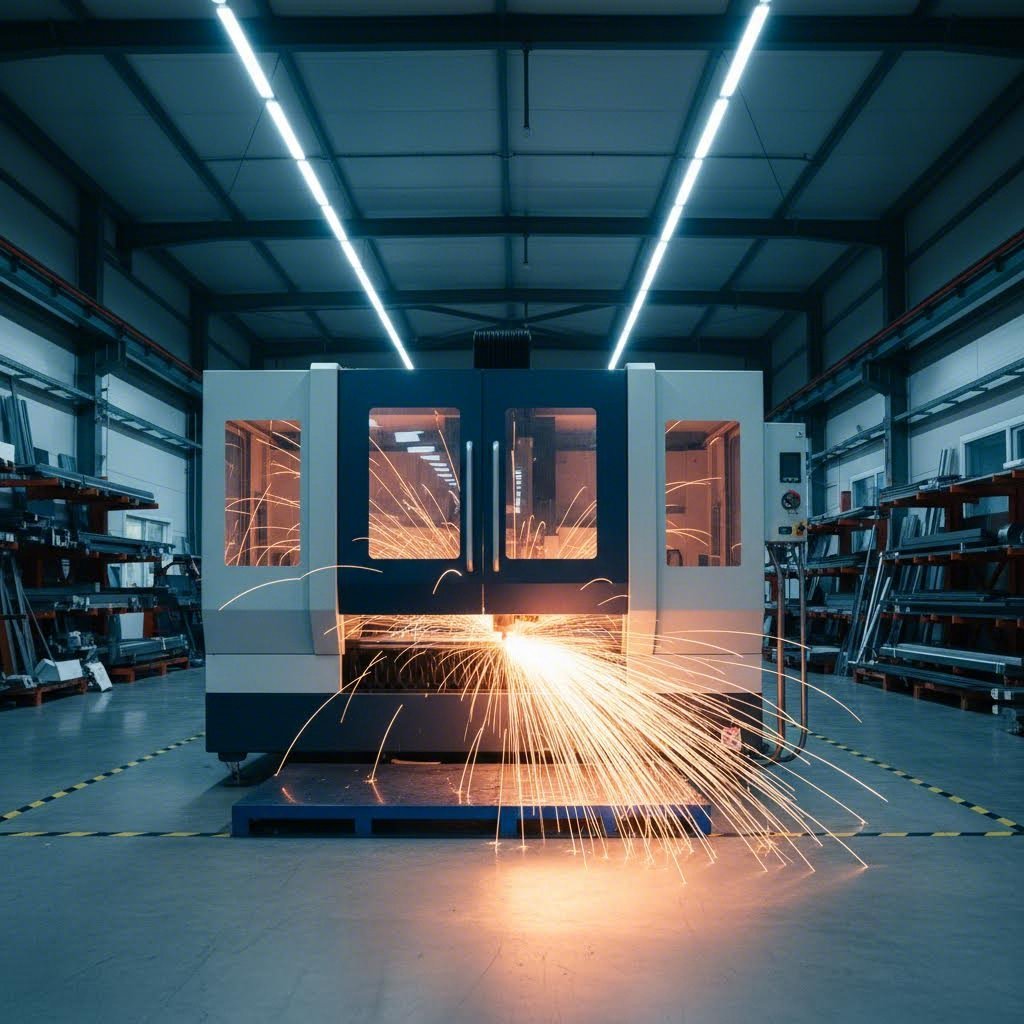
Every sheet metal component starts with cutting, and the method used directly impacts your part's accuracy and cost. Modern manufacturers rely primarily on three cutting technologies, each with distinct advantages.
Laser cutting dominates precision sheet metal work for good reason. A fiber laser cutter can hold tolerances of approximately ±0.005" (0.13 mm) on thin materials and ±0.010" (0.25 mm) as thickness increases. But here's something many buyers overlook: kerf width. The kerf—the material removed by the cutting beam—typically ranges from 0.006" to 0.015" depending on material, thickness, and nozzle setup.
Why does kerf matter? If you're designing tabs to fit into slots, ignoring kerf can mean the difference between parts that snap together perfectly and parts that require hammering or won't fit at all. A quality manufacturer compensates for kerf in their programming, but understanding this helps you design smarter from the start.
Plasma cutting handles thicker materials efficiently but with wider tolerances—typically ±0.030" or more. It's faster and more cost-effective for structural components where precision isn't critical.
Waterjet cutting excels with heat-sensitive materials or when you need to avoid thermal distortion entirely. There's no heat-affected zone, making it ideal for hardened materials or parts requiring subsequent heat treatment.
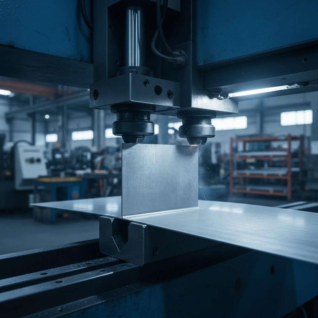
Forming and Bending Fundamentals
Once material is cut, bending transforms flat profiles into three-dimensional components. This is where understanding process capabilities becomes crucial for your design decisions.
Air bending on CNC press brakes is the most common forming method. Typical angle tolerances run ±1-2°, with bend location tolerances of ±0.015" to 0.030" depending on part length and complexity. The inside bend radius typically equals approximately the material thickness for standard air bending operations.
Here's a practical insight: the K-factor—a ratio that determines how much material shifts during bending—varies between 0.30 and 0.50 for steel. Your manufacturer uses this value to calculate flat pattern dimensions. Consistency matters more than hitting a specific number, so confirm your design uses the same K-factor your manufacturer applies.
Metal stamping enters the picture for high-volume production. When you need thousands or millions of identical parts, stamping delivers unmatched speed and per-piece economy. The tradeoff? Significant upfront tooling investment. Stamping makes sense when volume justifies tooling costs and when you need features difficult to achieve through bending alone.
Joining Methods for Structural Integrity
When components require permanent joining, welding method selection significantly affects strength, appearance, and cost. Understanding tig vs mig welding helps you specify the right approach for your application.
MIG welding (Metal Inert Gas) uses a continuously-fed consumable wire electrode with a shielding gas—typically 75% argon and 25% CO2. It's faster, more cost-effective, and easier to execute consistently. MIG is particularly effective for thicker materials and applications where weld aesthetics aren't the primary concern.
TIG welding (Tungsten Inert Gas) employs a non-consumable tungsten electrode with a separate filler rod, using 100% argon shielding. This method offers superior precision and stronger welds with excellent aesthetics—think of those perfectly stacked "coin" patterns you see on high-end fabrication. TIG excels for aluminum welding and thin materials where heat control is critical.
The tradeoff is clear: TIG costs more and takes longer but delivers cleaner, stronger joints. MIG provides speed and economy. For structural automotive components, MIG often suffices. For visible welds on architectural elements or aerospace applications requiring maximum strength, TIG is worth the investment.
| Process Name | Best For | Tolerance Capability | Volume Suitability | Cost Considerations |
|---|---|---|---|---|
| Laser Cutting | Precision profiles, intricate geometries | ±0.005" to ±0.010" | Low to high volume | Moderate; no tooling required |
| Plasma Cutting | Thick materials, structural parts | ±0.030" or wider | Low to medium volume | Lower cost for thick stock |
| CNC Bending | Forming angles, flanges, complex shapes | ±1-2° angle; ±0.015-0.030" location | All volumes | Standard tooling; minimal setup |
| Metal Stamping | High-volume identical parts | ±0.005" or tighter | High volume (10,000+ units) | High tooling; low per-piece cost |
| MIG Welding | Structural joints, thick materials | Dependent on operator skill | All volumes | Fast, economical |
| TIG Welding | Precision joints, thin materials, aluminum | Superior precision and strength | Low to medium volume | Higher cost; slower speed |
Understanding these processes transforms how you interact with manufacturers. Instead of simply handing over a drawing and hoping for the best, you can discuss specific capabilities, ask informed questions about tolerances, and make smarter decisions about which processes fit your application. When a metal cutter quotes your project, you'll know whether they're using the right approach—and you'll be equipped to push back when something doesn't align with your requirements.
With cutting and forming fundamentals covered, the next critical factor is material selection—because even perfect processes can't compensate for choosing the wrong material.
Material Selection Guide for Sheet Metal Components
You've got the manufacturing processes down. Now comes the decision that shapes everything else: which material do you actually need? Most manufacturers list available materials on their websites, but that doesn't help you understand why you'd choose one over another. Let's fix that.
Selecting the right sheet metal material isn't about picking the cheapest option or defaulting to whatever worked on your last project. It's about matching material properties to your application's specific demands—environmental exposure, load requirements, weight constraints, and cost targets.
Matching Materials to Application Demands
Think about what your component actually needs to survive. Will it face moisture, chemicals, or extreme temperatures? Does it need to be lightweight for transportation efficiency? Will it bear significant structural loads? Answering these questions narrows your options quickly.
Stainless steel sheet dominates applications requiring corrosion resistance and cleanability. The chromium content (typically 10.5% or higher) forms a protective oxide layer that prevents rust and resists degradation from moisture, chemicals, and repeated sanitization cycles. This makes stainless steel essential for food and beverage equipment, pharmaceutical manufacturing, marine environments, and medical devices where contamination isn't an option.
According to industry material experts, stainless steel can become discolored or experience surface rust with long-term exposure, particularly in high-salt environments. However, its corrosion resistance remains vastly superior to mild steels. One consideration buyers often overlook: bimetal corrosion risk. When stainless components contact dissimilar metals or fasteners, galvanic corrosion can occur—something your manufacturer should address during design review.
Aluminum sheet metal offers a compelling alternative when weight reduction matters. Aluminum weighs roughly one-third as much as steel, making it the go-to choice for aerospace applications, transportation equipment, and any component where every ounce counts. Its natural oxide layer provides excellent corrosion resistance without additional finishing in most environments.
Here's an insight that surprises many buyers: despite having lower tensile strength than steel, aluminum alloys often deliver higher specific strength—the strength-to-weight ratio that determines real-world performance in weight-sensitive applications. Material comparisons consistently show aluminum alloys outperforming steel when strength per unit mass is the metric that matters.
Aluminum also excels in thermal conductivity, dissipating heat approximately three times faster than steel. For electronics enclosures, heat sinks, or any component managing thermal loads, this property often drives material selection independent of weight considerations.
Steel plate (carbon steel or mild steel) remains the workhorse for structural applications where raw strength and cost-effectiveness trump other factors. When you need maximum load-bearing capacity at minimum material cost, steel delivers. Metal enclosures, tanks, heavy equipment brackets, and structural supports typically use steel for this reason.
The tradeoff? Carbon steel rusts aggressively without protective finishing. As one material specialist notes, unprotected steel sheets can begin rusting before fabrication even begins, sometimes requiring deburring or chemical treatment before surface finishing. Galvanized steel offers a cost-effective middle ground—the zinc coating provides corrosion protection, though cut edges remain vulnerable and may need secondary treatment.
Understanding Material Properties Beyond the Datasheet
Material datasheets provide numbers, but those numbers need context to drive smart decisions.
Tensile strength measures how much load a material withstands before permanent deformation (plastic deformation) occurs. This matters when your component bears structural loads, but evaluating strength requires nuance. Consider strength-by-cost when material volume is high and budgets are tight—mild steel typically wins here. Consider strength-by-weight when mass directly impacts performance or efficiency—aluminum often leads despite lower absolute strength values.
Gauge sizes define material thickness through a somewhat counterintuitive system: higher gauge numbers mean thinner material. Understanding common gauges helps you communicate requirements clearly and evaluate manufacturer capabilities.
For reference, 14 gauge steel thickness measures approximately 1.897 mm (0.0747") for standard steel—commonly used for moderate structural applications requiring good rigidity without excessive weight. Moving to 11 gauge steel thickness at approximately 3.048 mm (0.1200"), you're entering territory suited for heavier structural components, equipment housings, and applications demanding significant impact resistance.
One important detail: gauge thickness varies by material type. According to metal gauge specifications, a 16-gauge sheet measures 1.519 mm in standard steel but only 1.29 mm in aluminum, brass, or copper. Always confirm actual thickness in millimeters or inches rather than assuming gauge equivalency across materials.
Ductility (formability) determines how much a material can stretch during forming without cracking. Highly ductile materials tolerate tight bend radii and complex stamping operations. If your design includes aggressive forms, material ductility directly impacts manufacturing feasibility and tooling requirements.
| Material Type | Key Properties | Common Applications | Cost Tier | Fabrication Considerations |
|---|---|---|---|---|
| Stainless Steel (304/316) | Excellent corrosion resistance, high strength, food-safe | Food processing, medical devices, marine, pharmaceutical | High | Work hardens during forming; requires appropriate tooling and welding techniques |
| Aluminum (5052/6061) | Lightweight, good corrosion resistance, high thermal conductivity | Aerospace, electronics enclosures, transportation, heat dissipation | Medium-High | Softer material requires careful handling; specialized welding (TIG preferred) |
| Carbon Steel (Mild) | High strength, excellent weldability, cost-effective | Structural components, heavy equipment, enclosures, brackets | Low | Rusts without finishing; requires powder coating, painting, or galvanizing |
| Galvanized Steel | Moderate corrosion resistance, good strength | HVAC, outdoor enclosures, agricultural equipment | Low-Medium | Zinc coating provides protection; cut edges remain vulnerable to rust |
When evaluating a sheet metal component manufacturer, look beyond their material list. Ask how they help customers select materials—do they consider your application environment, structural requirements, and budget constraints? A manufacturer who simply processes whatever material you specify differs fundamentally from one who advises on material selection to optimize your project's outcome.
Material selection sets the foundation, but even the perfect material can't compensate for a design that's difficult or impossible to manufacture. That's where Design for Manufacturability principles come in.

Design for Manufacturability Principles
You've selected your material and understand the core manufacturing processes. Now comes the step that separates frustrating, expensive projects from smooth, cost-effective production: designing your part so it can actually be manufactured efficiently. This is Design for Manufacturability—or DFM—and it's the discipline that transforms good designs into great, production-ready components.
Here's the reality most engineers discover the hard way: a design that looks perfect in CAD can become a manufacturing nightmare. Bends that crack, holes that distort, tolerances that stack beyond acceptable limits—these issues drive up costs and delay timelines. The good news? Most problems are entirely preventable when you understand a few fundamental principles.
Design Decisions That Impact Production Cost
Every design choice carries manufacturing consequences. Understanding these relationships helps you make informed tradeoffs rather than discovering problems during production.
Bend radius requirements represent one of the most critical DFM considerations. When sheet metal bends, the outer surface stretches while the inner surface compresses. Make the bend radius too tight, and the material cracks. According to sheet metal DFM guidelines, the minimum bend radius should equal or exceed the material thickness for ductile materials like mild steel. For less ductile or hardened materials—such as aluminum 6061-T6—you'll need a minimum bend radius of 4x material thickness or greater to prevent cracking.
Why does this matter for costs? Tight bend radii require specialized tooling and slower processing speeds. They also increase rejection rates. When your manufacturer has to slow down, use custom tooling, or scrap parts that crack during forming, you pay the price.
Hole placement relative to bends catches many designers off guard. Place a hole too close to a bend line, and it will distort—stretching into an oval or tearing at the edges. The rule of thumb: position holes at least 2.5 times material thickness plus one bend radius away from any bend line. For a 14-gauge steel part (approximately 1.9 mm) with a standard bend radius, that means keeping holes roughly 6-8 mm minimum from the bend.
This isn't arbitrary—it's physics. Material flows during bending, and features too close to the deformation zone get dragged along for the ride. The same principle applies to slots, notches, and any punched feature.
Minimum flange heights often determine whether a part can be formed at all. If the flange is too short, there's insufficient material for the press brake tooling to grip and control. General guidance suggests minimum flange height should be at least 4 times material thickness plus the bend radius. Fail to meet this, and your manufacturer either can't produce the part or must use specialized (expensive) tooling.
Tolerance stacking becomes critical when multiple bends accumulate across a part. Each bend introduces its own variation—typically ±0.5° to ±1° for angle and ±0.015" for position. A part with five sequential bends can accumulate significant deviation at the final feature. Smart custom part design accounts for this by referencing critical dimensions from a single datum rather than across multiple bends, or by specifying tighter tolerances only where functionally necessary.
Avoiding Common Sheet Metal Design Mistakes
Some design errors appear repeatedly because they're not obvious until production begins. Here's how to avoid the most common pitfalls.
Cutouts too close to bends will stretch or flare when the sides get bent. According to manufacturing specialists, this is one of the most frequent design mistakes. The solution? Add bend relief—small notches at the ends of bend lines where they meet unbent material. Bend relief width should equal or exceed half the material thickness. This simple addition allows controlled deformation and prevents stress concentration that leads to tearing.
Ignoring grain direction can cause cracking in bends, particularly with heat-treated or less ductile materials like 6061-T6 aluminum. When possible, align bend lines perpendicular to the material's rolling direction. This isn't always practical for parts that must nest efficiently on sheet stock, but awareness of the tradeoff helps you make informed decisions.
Threaded insert placement requires careful consideration. A threaded insert installed too close to a bend or edge can distort during installation or fail under load because there's insufficient material surrounding it. Position inserts at least 3 times the insert diameter from edges and bends. For load-bearing applications, consult your manufacturer's recommendations—and consider their experience with specific insert types. A quality sheet metal component manufacturer will advise on optimal placement during DFM review.
Overlooking coating thickness trips up many designers. If your parts receive powder coating, you need to add approximately 0.003" to 0.005" per side to cutout dimensions. Skip this adjustment, and components won't fit into their intended openings after finishing. Reference your sheet metal gauge chart alongside coating specifications to ensure final dimensions meet requirements.
To keep your designs production-ready, follow these core DFM principles:
- Maintain minimum bend radii: Equal to material thickness for ductile materials; 3-4x thickness for hardened alloys
- Position holes correctly: At least 2.5x thickness plus bend radius from any bend line; 1.5x thickness from edges; 2x thickness apart from each other
- Design adequate flanges: Minimum height of 4x material thickness plus bend radius
- Include bend relief: Width equal to or greater than half material thickness at bend-to-flat transitions
- Specify tolerances strategically: Tight tolerances only where functionally required; standard tolerances elsewhere to reduce cost
- Account for finish thickness: Add coating allowance to cutout dimensions for powder-coated or plated parts
- Reference a screw size chart: Match fastener specifications to insert requirements and material thickness for proper engagement
Why early DFM consultation matters: The cost of design changes escalates dramatically as projects progress. Catching a problematic bend radius during design review costs nothing. Discovering it after tooling is cut or during first-article inspection? That's expensive rework, delayed schedules, and potentially scrapped tooling.
Quality manufacturers offer DFM review as part of their quoting process. They'll identify issues with your custom metal parts before production begins—tight tolerances that drive cost, features that can't be formed reliably, or dimensions that don't account for material behavior. This collaboration isn't a sign of weakness in your design; it's a smart use of manufacturing expertise to optimize outcomes.
When evaluating manufacturers, ask specifically about their DFM process. Do they review designs proactively, or simply quote and produce whatever you submit? The difference often determines whether your metal fabrication parts arrive on time, on budget, and ready for assembly—or become an expensive lesson in manufacturing reality.
With manufacturable designs in hand, the next consideration becomes tolerance capabilities—understanding what precision levels are achievable and what inspection methods verify compliance.
Tolerance Capabilities and Precision Standards
Here's a question that separates informed buyers from the rest: what tolerances can your manufacturer actually hold? It's not enough to know they have CNC equipment—you need to understand what precision levels are achievable for your specific application and how they verify compliance.
Standard sheet metal tolerances work perfectly for many applications. But when you're manufacturing precision components for medical devices, aerospace assemblies, or automotive safety systems, "standard" might not cut it. Understanding the difference—and knowing what to ask for—can mean the difference between parts that perform flawlessly and parts that fail in the field.
When Standard Tolerances Aren't Enough
According to industry fabrication standards, sheet metal manufacturing tolerances typically range from ±0.005" to ±0.060" depending on the process and material. That's a twelve-fold difference between the tightest and loosest acceptable variation. Where your project falls on that spectrum depends entirely on functional requirements.
For general-purpose enclosures or non-critical brackets, tolerances of ±0.030" to ±0.060" work fine. Parts assemble without issues, and the cost stays reasonable. But imagine a stainless steel sheet metal component that must mate precisely with machined surfaces in a surgical instrument. Suddenly, that ±0.030" variation becomes unacceptable—and you need a manufacturer capable of holding ±0.005" or tighter.
What drives the need for tighter tolerances? Consider these scenarios:
- Interchangeable assemblies: When parts from different production runs must fit together without adjustment, consistent tight tolerances ensure compatibility
- Precision interfaces: Components mating with machined parts or electronic assemblies require dimensional accuracy that matches their counterparts
- Stacked assemblies: When multiple sheet metal parts combine, tolerance accumulation can push final dimensions outside acceptable limits unless each component is held tight
- Regulatory compliance: Medical, aerospace, and automotive applications often mandate specific tolerance requirements for certification
Think of tolerances like the rungs on a ladder. Just as you'd reference a drill size chart or drill bit size chart to select the right tool for a specific hole diameter, you need to match tolerance requirements to application demands. Specifying tighter tolerances than necessary wastes money; specifying tolerances too loose risks functional failure.
Precision Requirements by Industry
Different industries demand different precision levels, and understanding these expectations helps you evaluate whether a manufacturer can serve your needs.
The automotive sector typically requires tolerances of ±0.010" to ±0.020" for structural and chassis components. For precision fabricated components in safety-critical systems, requirements tighten to ±0.005". Manufacturers serving this industry must demonstrate consistent capability through statistical process control and first-article inspection protocols.
Aerospace applications push precision requirements even further. Flight-critical components often demand tolerances of ±0.003" to ±0.005"—achievable only with advanced equipment, controlled environments, and rigorous inspection. The cost premium is significant, but so are the consequences of failure.
Medical device manufacturing requires not just tight tolerances but complete traceability. According to tolerancing specialists, these applications demand tolerances ensuring multi-faceted compatibility and standardized applicability—typically ±0.005" to ±0.010" depending on component function.
Electronics enclosures and EMI shielding present unique challenges. While overall dimensions might tolerate ±0.015", critical features like connector cutouts or mounting holes often require ±0.005" to ensure proper fit with standardized components. Reference a screw diameter chart to confirm fastener locations align with industry-standard hardware specifications.
| Application Type | Typical Tolerance Required | Recommended Process | Quality Verification Method |
|---|---|---|---|
| General enclosures, brackets | ±0.030" to ±0.060" | Standard laser cutting, CNC bending | Visual inspection, manual gauging |
| Automotive structural components | ±0.010" to ±0.020" | Precision laser cutting, stamping | Go/no-go gauging, SPC monitoring |
| Medical device housings | ±0.005" to ±0.010" | Fine-blanking, precision stamping | CMM measurement, 100% inspection |
| Aerospace precision parts | ±0.003" to ±0.005" | Precision stamping, EDM finishing | CMM with full documentation |
| Electronics/EMI shielding | ±0.005" to ±0.015" | Laser cutting, precision forming | Optical comparators, CMM spot-checks |
How do different processes achieve these tolerance levels? It comes down to equipment capability and process control. As noted in fabrication tolerance guides, laser cutting typically achieves ±0.005" on parts under 100mm, loosening to approximately ±0.5mm for larger components. Stamping can hold ±0.001" or tighter for critical features when dies are precision-ground and properly maintained. Bending introduces more variation—typically ±0.5° angular and ±0.4mm to ±0.8mm linear—making it the operation most likely to challenge tight tolerance requirements.
Inspection Methods That Verify Precision
Claiming tolerance capability means nothing without verification methods to prove it. When evaluating a sheet metal component manufacturer, ask specifically about their inspection protocols.
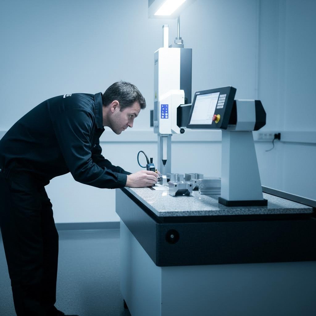
Coordinate Measuring Machines (CMM) represent the gold standard for metal parts manufacturing verification. These precision instruments use touch probes to collect 3D coordinate data, capable of measuring complex geometries with micron-level accuracy. According to quality inspection specialists, CMM measurement provides comprehensive deviation reports comparing actual dimensions against CAD models.
Go/no-go gauging offers rapid pass/fail verification for production environments. These hardened gauges check critical dimensions instantly—if the part fits the gauge, it passes; if not, it's rejected. This method works well for high-volume production where 100% inspection is impractical but critical dimensions must be verified.
Optical comparators project magnified part profiles onto screens with overlay templates, enabling rapid visual comparison of 2D contours, hole patterns, and edge conditions. They're particularly effective for verifying complex profiles and detecting deviations that might escape manual measurement.
Visual inspection standards address surface quality rather than dimensions—scratches, dents, burr conditions, and finish consistency. While often considered subjective, formal visual standards define acceptable limits and require trained inspectors to ensure consistency.
The key question: does your manufacturer match inspection methods to tolerance requirements? Parts with ±0.030" tolerances don't need CMM verification—it's overkill. But precision components requiring ±0.005" absolutely do. A manufacturer who applies the same inspection approach to everything either over-inspects simple parts (adding cost) or under-inspects critical ones (risking quality escapes).
Understanding tolerance capabilities and verification methods positions you to evaluate manufacturers objectively. But tolerances alone don't guarantee quality—that requires systematic processes backed by recognized certifications.
Quality Certifications and Compliance Requirements
You've seen the logos on manufacturer websites—ISO 9001, IATF 16949, AS9100. But what do these certifications actually mean for your project? Most manufacturers display certification badges without explaining their significance, leaving buyers to wonder whether these credentials represent genuine quality commitment or merely marketing decoration.
Here's the truth: certifications matter enormously—but only when you understand what they verify and how they affect your parts. A certified quality management system directly impacts part reliability, traceability, and your ability to trust that every component meets specifications consistently.
Decoding Quality Certifications
Quality certifications aren't arbitrary checklists. They represent structured frameworks that govern how manufacturers plan, control, measure, and improve their operations. Understanding what each certification demands helps you evaluate whether a manufacturer's credentials align with your application requirements.
ISO 9001:2015 serves as the foundational quality standard for manufacturing operations worldwide. According to industry implementation guides, ISO 9001 defines requirements for a Quality Management System (QMS) that standardizes processes from quoting through final shipment. The 2015 revision added risk-based thinking, process integration, and leadership accountability—all directly relevant to custom metal products manufacturing.
For sheet metal fabricators, ISO 9001 certification means:
- Documented procedures: Every critical process—cutting, bending, welding, inspection—follows controlled procedures that ensure repeatability
- Calibrated equipment: Measurement tools and production equipment undergo regular calibration against traceable standards
- Trained personnel: Operators receive documented training with verified competency before performing quality-critical operations
- Continuous improvement: Systematic analysis of defects, returns, and process variations drives ongoing quality enhancement
Case studies demonstrate measurable impact. One 50-person custom fabrication shop documented significant improvements after ISO 9001 implementation: internal scrap rates dropped, customer complaints decreased, and first-article approval rates improved—while also boosting morale and client confidence.
IATF 16949 builds on ISO 9001 with automotive-specific requirements that address the unique demands of vehicle manufacturing supply chains. According to automotive industry specialists, IATF 16949 goes far beyond quality procedures—it's specifically designed as a holistic review of a supplier's systems including supply chain diversification and risk, management response procedures, and continuous improvement and process reviews.
Why does automotive manufacturing demand this elevated standard? The consequences of quality failures cascade rapidly through complex supply chains. A defective bracket or mounting component can trigger line-down situations at OEMs, causing massive expense throughout the system. IATF certification demonstrates that a metal parts manufacturer has systems in place to prevent such disruptions.
Key IATF 16949 requirements beyond ISO 9001 include:
- Advanced Product Quality Planning (APQP): Structured development processes ensuring new parts are production-ready before launch
- Production Part Approval Process (PPAP): Documented evidence that manufacturing processes consistently produce parts meeting specifications
- Failure Mode and Effects Analysis (FMEA): Systematic identification and mitigation of potential failure modes before they occur
- Supply chain risk management: Documented strategies for maintaining supply continuity during disruptions
It's becoming commonplace for OEMs and Tier 1 suppliers to require IATF programs, as their value has been demonstrated in keeping supply arrangements running smoothly. When sourcing custom stainless steel parts or any fabricated metal parts for automotive applications, IATF 16949 certification should be non-negotiable.
What Compliance Really Means for Your Parts
Certification represents capability, but actual quality comes from day-to-day execution. Understanding the quality control processes behind certifications helps you evaluate whether a manufacturer truly delivers on their credentials.
Incoming material inspection catches problems before they propagate. According to quality control specialists, the quality of metal is the first and most important consideration. Certified manufacturers verify material certifications, check dimensional conformance of incoming stock, and may perform hardness testing, tensile strength tests, and chemical analysis to confirm material integrity before any fabrication begins.
In-process checks prevent defects from accumulating. Visual inspection at different stages of processing is vital to detect defects and imperfections—whether mass production or small-scale runs. For small metal parts manufacturing especially, catching dimensional drift early prevents producing entire batches of non-conforming parts. Statistical Process Control (SPC) tracks critical dimensions throughout production runs, flagging trends before they become rejections.
Final inspection protocols verify that finished custom manufactured parts meet all specifications. This includes dimensional verification using appropriate methods—CMM measurement for precision components, go/no-go gauging for high-volume production, visual inspection for surface quality. Random sampling may suffice for lower-criticality applications, while 100% inspection applies to safety-critical components.
Documentation requirements enable traceability—the ability to trace any part back to its raw material source, production date, operator, and inspection results. Why does this matter? When problems occur months or years later, traceability identifies affected parts and scope of potential issues. For regulated industries, traceability isn't optional—it's a fundamental requirement.
Keeping detailed documentation of inspection and testing processes helps identify stages where issues were found and what measures addressed them. This documentation also protects against unexpected quality disputes by providing objective evidence of conformance at shipment.
Certifications and Their Industry Relevance
Different applications demand different certification levels. Here's how major certifications align with industry requirements:
- ISO 9001: Universal baseline for quality management; appropriate for general industrial, commercial, and consumer product applications
- IATF 16949: Required for automotive supply chain; demonstrates capability for high-volume, zero-defect production with complete traceability
- AS9100: Aerospace-specific standard building on ISO 9001 with additional requirements for configuration management, risk mitigation, and supply chain controls
- ISO 13485: Medical device quality management; addresses regulatory requirements for devices affecting patient safety
- NADCAP: Special process accreditation for aerospace heat treating, welding, and other critical operations
Certification matters beyond marketing claims because it represents third-party verification that systems actually function as documented. Annual surveillance audits and triennial recertification audits ensure ongoing compliance—not just a one-time achievement. When a manufacturer displays certification logos, they're demonstrating commitment to external accountability that goes far beyond self-declaration.
For your projects, this translates to reduced risk. Certified manufacturers have proven systems for preventing, detecting, and correcting quality issues. Their processes are designed for consistency, not just occasional good results. And when problems do occur, documentation and traceability enable rapid root cause analysis and corrective action.
Certifications and quality processes establish capability, but choosing the right manufacturing method for your specific volume and complexity requirements determines whether that capability translates to cost-effective production.
Comparing Manufacturing Methods
You've selected your material, optimized your design for manufacturability, and understand tolerance requirements. Now comes a decision that directly impacts your project economics: which manufacturing method makes sense for your specific situation? The answer isn't always obvious—and getting it wrong can mean either paying too much per part or investing in tooling you'll never recoup.
Here's what most buyers discover too late: the "best" manufacturing method depends almost entirely on your production volume, timeline, and how likely your design is to change. A method that saves money at 50,000 units might be financially disastrous at 500 units. Understanding these crossover points transforms you from a passive buyer into a strategic sourcing partner.
Choosing the Right Manufacturing Method
Three primary approaches dominate sheet metal component production, each with distinct advantages that align with different project requirements.
Metal stamping delivers unmatched efficiency for high-volume production. Once custom dies are built, stamping presses can produce thousands of identical parts per hour with exceptional consistency. According to industry fabrication specialists, stamping is synonymous with high production volumes, capable of cranking out quantities from tens to hundreds of thousands of units per year.
But stamping comes with a significant catch: tooling investment. Custom dies typically cost tens of thousands of dollars, raising the stakes considerably when making outsourcing decisions. And here's what many buyers overlook—stamping is inherently inflexible. Once the die is set, design changes cannot be made without tooling revisions and their associated costs. Even "permanent" stamping dies have a maximum useful life of typically three years before deformations create excess material waste and non-conformance issues.
Laser-based fabrication offers a compelling alternative that's reshaping traditional volume assumptions. Modern fiber laser systems combined with advanced press brakes can now support production volumes that were previously reserved exclusively for stamping—around 30,000 and even up to 50,000 annual units in some cases, according to manufacturers pushing the technology's boundaries.
The key advantage? No tooling investment. Your manufacturer simply programs the laser cutter and press brake based on your CAD files. Need to modify a feature or improve the design? It's a program change, not a die revision. This flexibility proves invaluable for products undergoing iterative engineering improvements or design updates—you don't have to wait years to update tooling before making product improvements.
Precision machining enters the equation when tolerances exceed what forming operations can reliably achieve, or when complex 3D geometries can't be created through bending alone. CNC machining removes material rather than forming it, enabling tolerances of ±0.001" or tighter on critical features. For hybrid approaches, manufacturers often combine stamped or fabricated base components with machined features where precision matters most.
Volume Considerations in Method Selection
Understanding cost crossover points helps you make economically sound decisions. The relationship between volume and method selection isn't arbitrary—it's driven by how fixed costs (tooling, programming) amortize across production quantities.
For prototype sheet metal parts and low-volume production (typically under 500 units), fabrication almost always wins. There's no tooling to amortize, lead times are shorter, and design flexibility remains intact. According to prototype-to-production specialists, rapid prototyping approaches help you produce prototypes much faster while allowing modifications based on feedback—avoiding the commitment of production tooling until designs are finalized.
The middle ground—roughly 500 to 25,000 units annually—requires careful analysis. Fabrication remains viable and often cost-competitive, especially when design stability is uncertain. But as volumes increase, stamping's lower per-piece cost begins offsetting tooling investment. The exact crossover depends on part complexity, material costs, and how many years of production you're planning.
At higher volumes (25,000+ units annually), stamping typically delivers the lowest total cost—assuming your design is stable and production will continue long enough to justify tooling. Steel fabricators and stamping specialists will analyze your specific requirements to recommend the optimal approach.
| Method | Ideal Volume Range | Tooling Cost | Per-Part Cost Trend | Lead Time Factors |
|---|---|---|---|---|
| Laser Fabrication | 1 to 30,000+ units/year | None (programming only) | Relatively flat; modest decrease at volume | Days to weeks; quick setup |
| Metal Stamping | 10,000+ units/year | $15,000 to $100,000+ | High initially; drops significantly at volume | Weeks to months for tooling; fast production |
| CNC Machining | 1 to 5,000 units/year | Minimal (fixtures only) | Higher per-part; stable across volumes | Days to weeks; depends on complexity |
| Hybrid (Fab + Machining) | 100 to 10,000 units/year | Low to moderate | Moderate; balances precision with economy | Longer due to multiple operations |
Quick turn sheet metal fabrication scenarios deserve special consideration. When speed justifies premium pricing—urgent prototypes for trade shows, replacement parts keeping production lines running, or accelerated product launches—fabrication's lack of tooling requirements becomes decisive. You simply can't stamp parts quickly without existing dies.
When does speed justify the cost premium? Consider these situations:
- Production line down: A failed component halting assembly operations costs thousands per hour in lost productivity—expedited fabrication pays for itself within days
- Market timing: Launching ahead of competitors or meeting seasonal windows may generate revenue that dwarfs any fabrication premium
- Design validation: Getting functional metal sheets into testing quickly prevents costly delays later in development
- Customer commitments: Meeting delivery promises protects relationships worth far more than short-term cost differences
Custom metal parts fabrication also enables hybrid approaches that optimize both cost and capability. Consider a complex assembly requiring precise mounting interfaces but standard structural elements. Fabricating the metal sheet components through laser cutting and bending keeps costs reasonable, while machining only the critical interface features achieves required tolerances without premium pricing across the entire part.
The decision framework ultimately comes down to three questions: What's your expected annual volume? How stable is your design? And how quickly do you need parts? Honest answers guide you toward the manufacturing method that delivers the best combination of cost, quality, and flexibility for your specific situation.
With manufacturing method selection clarified, the final step is evaluating potential manufacturers themselves—assessing their capabilities, communication quality, and alignment with your project requirements.
How to Evaluate Sheet Metal Manufacturers
You understand the processes, materials, and manufacturing methods. Now comes the decision that determines whether all that knowledge translates into successful production: choosing the right manufacturing partner. This isn't about finding the cheapest option or the flashiest website—it's about identifying a manufacturer whose capabilities, communication style, and quality systems align with your specific project requirements.
When you search for "metal fabrication near me" or "fabrication shops near me," you'll find dozens of options. The challenge isn't finding manufacturers—it's evaluating them objectively. Let's break down exactly how to do that.
Evaluating Manufacturer Capabilities
Before requesting quotes, you need to assess whether a manufacturer can actually deliver what you need. According to manufacturing evaluation specialists, selecting a manufacturer to produce your new product is a high-stakes decision that deserves structured assessment.
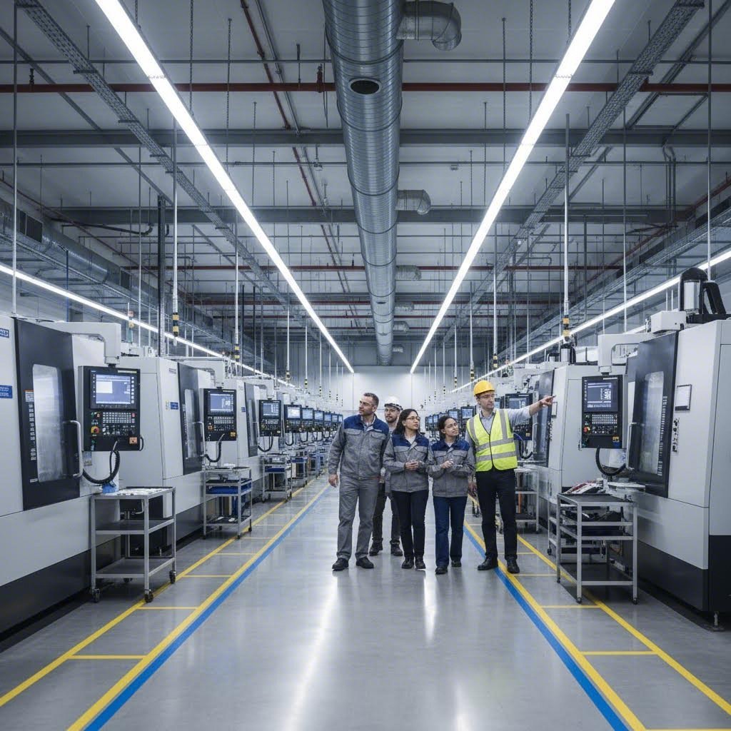
Start with an introductory meeting—allow 2-3 hours for a company introduction, facility tour, and discussion of your project. Pay attention to who attends. Is it just a sales representative, or do technical managers participate? Both should be present for meaningful capability discussions. Did they review information you sent beforehand? Did they prepare questions about your specific requirements?
During facility tours, assess general cleanliness and orderliness. This may seem superficial, but it often indicates how carefully they handle products. Look for signs of their focus: high-volume/low-cost operations look different from high-quality development environments. Note the level of automation versus manual labor, whether the facility appears fully utilized, and what safety measures are visible.
Ask specifically about in-house versus outsourced processes. Sheet metal prototyping services might be handled differently than production runs. Understand their tooling capabilities, supply chain management processes, and whether they have engineering teams to manage design changes. Companies that manufacture custom metal parts should have clear design change control and process change procedures.
Questions to Ask Before Committing
The quality of questions you ask reveals your sophistication as a buyer—and the quality of answers reveals a manufacturer's true capabilities. Here's what to explore:
- Technical capabilities: What manufacturing processes do they have in-house? What tolerances can they reliably hold? What materials do they work with regularly? Ask for examples of similar projects they've completed.
- Quality systems: What certifications do they hold? How do they manage incoming material quality? Can they explain how they'll develop quality checks for your specific product? Do they track serial numbers, lot numbers, and batch information for traceability?
- Communication responsiveness: What's their typical response time for technical questions? Who will be your primary contact? How do they handle urgent requests or schedule changes?
- Design support availability: Do they offer DFM review? Will they proactively suggest design improvements, or simply manufacture whatever you submit? What's their process for managing engineering changes during production?
- Production capacity: Can they scale with your growth? What's their current utilization? How do they prioritize when capacity gets tight? Ask about their typical lead times for projects similar to yours.
- Geographic considerations: Where are they located relative to your operations? How does location affect shipping costs and lead times? For custom metal parts fabrication near me searches, proximity can significantly impact total cost and responsiveness.
Intellectual property protection deserves specific attention. Ask directly whether the manufacturer works with any competing brands—by name. If they do, what systems prevent competitors from learning each other's trade secrets? According to vendor assessment experts, the vendor should have a clear statement of intellectual property protection.
Domestic Versus Overseas Manufacturing
The decision between domestic and international sourcing involves more than unit cost comparisons. According to metal sourcing specialists, your sourcing choice directly impacts timelines, budget, and peace of mind.
Advantages of Domestic Sourcing
Speed stands out immediately. Because your supplier is just a truck ride away, lead times are shorter, and shipping is quicker. There's far less risk of delays from customs, port congestion, or global shipping disruptions. The COVID-19 pandemic highlighted how fragile international logistics can be.
Quality consistency improves with domestic partners. U.S. suppliers adhere to strict industry standards and certifications, ensuring materials meet your specifications. Local oversight means issues get addressed swiftly, reducing chances of receiving subpar products.
Communication becomes dramatically easier. Same time zone, no language barriers, and cultural alignment enable collaborative relationships. Need to make adjustments or have urgent requests? It's much easier to resolve things quickly with a local partner.
Flexibility often favors domestic manufacturers. They can adapt quickly—speeding up delivery, customizing orders, or accommodating special requests—without the coordination challenges of overseas operations.
Challenges with Overseas Sourcing
While international suppliers may offer lower unit prices, hidden costs accumulate. Shipping fees, tariffs, duties, and currency exchange rates can turn that low-cost order into a pricier endeavor than expected. As sourcing experts note, what seems like a good deal on paper can quickly add up.
Quality becomes a gamble without ability to regularly inspect facilities or materials. You may deal with inconsistent products or compliance issues. Working across time zones with potential language barriers leads to misunderstandings, response delays, and supply chain disruptions.
For metal fabricators near me searches, domestic options typically deliver better total value when factoring in reduced risk, faster response, and lower coordination overhead—even if unit prices appear higher initially.
Understanding the Sheet Metal Quote Process
When you request a sheet metal quote, you're initiating a process that reveals much about a manufacturer's capabilities and professionalism. Understanding what to expect—and how to compare quotes fairly—prevents costly mistakes.
According to custom fabrication specialists, while it's tempting to focus on the dollar amount, there's truth to the saying "you get what you pay for." A lower quoted price could mean cutting corners on material quality, low-quality workmanship from inexperienced fabricators, subcontracting to unknown third parties, outdated equipment, or lack of experience in your industry.
Before soliciting bids, pre-qualify manufacturers. Only request quotes from companies you feel confident partnering with. Custom fabrication requires experience, expertise, high-quality equipment, and strong customer service. You want staff that values certifications, state-of-the-art equipment, continuous improvement processes, and responsive communication.
When comparing quotes, ensure you're comparing apples to apples:
- Material specifications: Are all quotes based on identical material grades and thicknesses?
- Finishing requirements: Does the quote include all specified surface treatments, coatings, or plating?
- Inspection level: What quality verification is included? First-article inspection? In-process checks? Final dimensional verification?
- Packaging and shipping: Are these costs included or additional?
- Tooling ownership: Who owns any fixtures or tooling created for your project?
- Lead time commitments: What's the quoted delivery timeline, and what penalties exist for delays?
The lowest quote may be tempting, but as fabrication experts emphasize, a facility with outdated equipment and inexperienced staff may cost you far more due to errors before the project completes. Rather than finding the cheapest partner, focus on finding one with a reputation for producing quality products.
Red Flags to Avoid
Certain warning signs should give you pause during evaluation:
- Vague capability claims: If they can't specify tolerances, equipment types, or certifications clearly, their capabilities may be limited
- Reluctance to show the facility: Manufacturers confident in their operations welcome facility tours; resistance suggests something to hide
- No questions about your application: A manufacturer who doesn't ask about end-use, volumes, or quality requirements may not understand what success looks like for your project
- Unusually fast quotes: Complex projects deserve careful review; instant pricing may indicate template responses rather than genuine analysis
- No DFM feedback: If they simply quote your design without suggestions for improvement, you're missing valuable manufacturing expertise
- Poor communication during quoting: If response times are slow and answers unclear before you're a customer, expect worse after you've committed
Look for transparency in processes. Choose a partner who is proud to show their facility and allow you to see quality work they've completed. When you invest in a high-quality manufacturing partner, you can be assured of receiving high-quality products—and that's always worth it in the end.
With evaluation criteria established, you're ready to move forward confidently—knowing how to identify manufacturers whose capabilities genuinely match your requirements.
Moving Forward with Your Sheet Metal Project
You've now explored every critical dimension of evaluating a sheet metal component manufacturer—from core processes and material selection to DFM principles, tolerance capabilities, quality certifications, manufacturing methods, and vendor assessment strategies. The question becomes: what do you do with all this knowledge?
The answer is straightforward. You take action. Armed with a clear understanding of what separates capable manufacturers from mediocre ones, you're positioned to make sourcing decisions that protect your timelines, budgets, and product quality.
Taking the Next Step in Your Manufacturing Journey
Start by defining your project requirements with precision. Before reaching out to potential partners, document the essentials: material specifications, expected volumes, tolerance requirements, certification needs, and target timelines. The more clearly you articulate these parameters, the more accurate quotes you'll receive—and the easier it becomes to compare manufacturers objectively.
Next, create your evaluation shortlist. Apply the criteria we've discussed: technical capabilities matching your sheet metal components, relevant industry certifications, demonstrated DFM expertise, and communication responsiveness. For custom metal components requiring automotive-grade quality, prioritize IATF 16949-certified manufacturers with proven track records in your specific application area.
Request quotes from three to five qualified candidates. Remember—you're not just comparing prices. You're assessing how each manufacturer approaches your project. Do they ask intelligent questions about your application? Do they offer DFM suggestions that could reduce costs or improve quality? Do they respond promptly and professionally?
Schedule facility visits for your top candidates when possible. As we discussed earlier, a custom parts manufacturer's shop floor reveals truths that websites cannot. Cleanliness, equipment condition, and staff engagement all indicate operational discipline that directly affects your parts.
Partnering for Production Success
The manufacturers who deliver consistent results share common characteristics. They invest in modern equipment, maintain rigorous quality systems, employ skilled personnel, and prioritize customer communication. Finding a partner who checks all these boxes transforms sourcing from a transactional headache into a competitive advantage.
The ideal sheet metal component manufacturer combines rapid prototyping capabilities, comprehensive DFM support, IATF 16949 certification, and responsive communication—enabling you to move from concept to production with confidence and speed.
For automotive applications specifically, these requirements become non-negotiable. Chassis, suspension, and structural sheet metal pieces demand manufacturers who understand the stakes—where quality escapes cascade through supply chains and tolerance deviations compromise safety.
Consider what responsive partnership looks like in practice. Shaoyi (Ningbo) Metal Technology exemplifies the capabilities discussed throughout this guide. Their 5-day rapid prototyping addresses the speed concerns we explored in manufacturing method selection. Their 12-hour quote turnaround demonstrates the communication responsiveness that separates serious partners from passive vendors. And their comprehensive DFM support connects directly to the design principles that prevent costly production issues.
With IATF 16949 certification backing their quality systems, Shaoyi delivers custom metal assemblies for automotive applications—from initial prototypes through automated mass production. For buyers sourcing precision stamped components and sheet metal near me alternatives, manufacturers with this combination of speed, quality certification, and engineering support represent the partnership model that drives production success.
Whatever your application—automotive, aerospace, medical, or industrial—the evaluation framework remains consistent. Match manufacturer capabilities to your specific requirements. Verify credentials through facility assessment and reference checks. Prioritize communication quality alongside technical competence. And remember that the lowest quote rarely delivers the lowest total cost.
Your next sheet metal project deserves a manufacturing partner who treats your success as their own. With the knowledge you've gained here, you're equipped to find exactly that.
Frequently Asked Questions About Sheet Metal Component Manufacturers
1. What services do sheet metal fabrication companies offer?
Sheet metal fabrication companies typically offer laser cutting, CNC bending, metal stamping, welding (MIG and TIG), assembly integration, and finishing services. Quality manufacturers also provide Design for Manufacturability (DFM) support, helping optimize designs before production. Services range from rapid prototyping with 5-day turnarounds to high-volume automated mass production, with capabilities for installing threaded inserts and creating custom metal assemblies for automotive, aerospace, medical, and electronics industries.
2. How do I find custom metal parts fabrication near me?
Start by identifying manufacturers with relevant certifications like ISO 9001 or IATF 16949 for automotive applications. Request facility tours to assess equipment condition and cleanliness. Evaluate their technical capabilities, including tolerance levels and in-house processes. Compare quotes based on material specifications, inspection levels, and lead times—not just price. Domestic manufacturers often provide faster turnaround, easier communication, and reduced shipping risks compared to overseas options.
3. What is the difference between sheet metal fabrication and metal stamping?
Sheet metal fabrication uses laser cutting and CNC bending to produce parts without dedicated tooling, making it ideal for prototypes and volumes up to 30,000 units annually. Metal stamping uses custom dies to produce high-volume parts (10,000+ units) with exceptional speed and consistency but requires significant upfront tooling investment of $15,000 to $100,000 or more. Stamping offers lower per-piece costs at scale but lacks design flexibility once dies are created.
4. What certifications should a sheet metal manufacturer have?
ISO 9001 provides the foundational quality management baseline for general industrial applications. IATF 16949 is essential for automotive supply chain work, adding requirements like APQP, PPAP, and FMEA. AS9100 covers aerospace applications, while ISO 13485 addresses medical device manufacturing. These third-party certifications verify documented procedures, calibrated equipment, trained personnel, and continuous improvement systems—ensuring consistent quality beyond marketing claims.
5. How long does custom sheet metal fabrication take?
Lead times vary by manufacturing method and complexity. Laser-based fabrication typically delivers parts in days to weeks with minimal setup time. Metal stamping requires weeks to months for initial tooling but produces parts rapidly once dies are complete. Quick-turn fabrication services can deliver prototype sheet metal parts within 2-5 days. Manufacturers like Shaoyi offer 5-day rapid prototyping and 12-hour quote turnaround for automotive components, accelerating development timelines significantly.