 Serii mici, standarde ridicate. Serviciul nostru de prototipare rapidă face validarea mai rapidă și mai ușoară —

Întreținerea preventivă a matrițelor de ambutisare: detectați uzura înainte de apariția rebuturilor
De ce este importantă întreținerea preventivă
Sună complicat? Întreținerea preventivă a matrițelor de ambutisare este pur și simplu o îngrijire planificată și repetabilă a matrițelor, efectuată înainte ca o defecțiune să perturbe producția. În termeni practici, aceasta înseamnă curățarea, inspecția, ungerea, strângerea și întreținerea componentelor supuse uzurii, conform unui program stabilit, astfel încât matrița să continue să producă piese acceptabile, în siguranță și în mod constant.
Întreținerea preventivă a matrițelor de ambutisare reprezintă lucrări programate care controlează uzura normală înainte ca aceasta să conducă la rebuturi, timp nefolositor sau deteriorarea matriței.
Ce cuprinde întreținerea preventivă a matrițelor de ambutisare
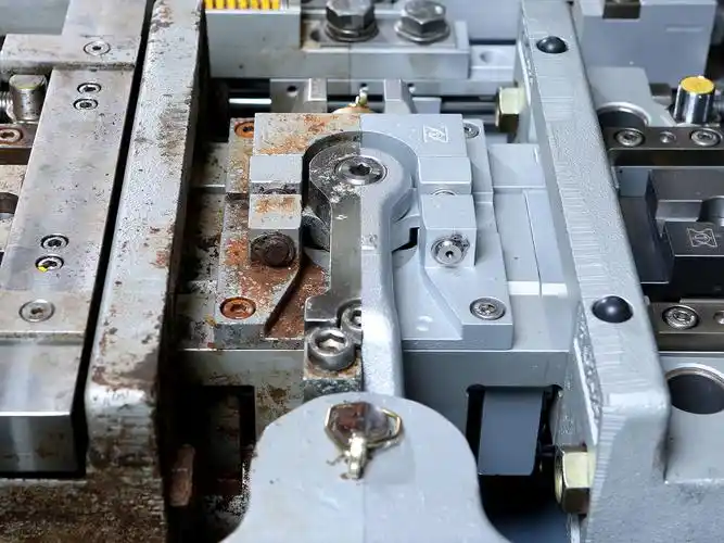
O întreținere corectă a matrițelor de ambutisare se concentrează pe matriță ca pe un sistem, nu doar pe un detaliu deteriorat. Aceasta include poansoanele, secțiunile matriței, plăcile de extracție care controlează eliberarea materialului, elementele de ghidare, cum ar fi pinoanele și bucșele de ghidare, arcurile, dispozitivele de fixare, elementele de prindere, senzorii și punctele de ungere. Tălpile matriței, sau plăcile matriței, susțin aceste componente, în timp ce butoanele oferă muchia opusă de tăiere pentru poansoane. Atunci când aceste piese rămân curate, aliniate, fixate corect și udate corespunzător, întreținerea sculelor devine mult mai previzibilă.
De ce întreținerea planificată protejează calitatea și productivitatea
Suprafețele de producție simt de obicei întreținerea matrițelor doar atunci când apare o problemă. Totuși, beneficiul major apare mai devreme. Art Hedrick subliniază în Fabricantul că întreținerea reală include ascuțirea pentru uzura normală, înlocuirea arcurilor înainte de expirarea duratei de viață așteptate, curățarea matrițelor, verificarea prezenței penelor de centrare sau a secțiunilor slăbite, precum și rectificarea și ungerea, după caz.
- Reduce timpul nefolositor neplanificat și întreruperile presei
- Ajută la controlul bavurilor, problemelor de alimentare și variațiilor dimensionale
- Prelungirea duratei de viață a matriței prin limitarea șocurilor, jocurilor și uzurii necontrolate
- Sprijinirea unei funcționări mai sigure a presei prin menținerea dispozitivelor de protecție și a componentelor în poziția lor corectă
- Reducerea frecvenței și urgenței reparațiilor matriței
Lucrări preventive vs. corective vs. predictive
Lucrările preventive sunt programate în avans. Lucrările corective au loc după apariția unei defecțiuni și necesită restabilirea funcționalității. Lucrările predictive folosesc date despre starea echipamentului, adesea obținute din senzori și dispozitive de monitorizare, pentru a prognoza momentul în care este necesară întreținerea. Pe scurt, întreținerea preventivă previne apariția defecțiunilor, întreținerea corectivă remediază defecțiunile existente, iar întreținerea predictivă anticipează apariția acestora. Această distincție este esențială, deoarece pierderea calității rar începe ca o defecțiune bruscă și gravă. Mai degrabă, aceasta apare inițial sub forma unui bavură, a unei zgârieturi, a unei alimentări neregulate sau a unei ușoare devieri în aliniere.
Defecțiuni care semnalează probleme la matriță
Când începeți să observați un bavură pe piese care ieri erau fără defecte, unde ar trebui să căutați întâi? În cadrul întreținerii preventive a matrițelor de ambutisare, răspunsul cel mai rapid nu este întotdeauna muchia de tăiere. Datele din atelier partajate de Formare metalică arată că alimentările defectuoase sunt adesea cea mai frecventă problemă legată de matrițe, urmate de la mică distanță de tragerea deșeurilor. Acest lucru este un reamintitor util: defecțiunile vizibile încep adesea cu deriva setării, deșeurile slabe, problemele de ungere sau pierderea alinierii, înainte de a se transforma în reparații complexe ale matriței.
Moduri comune de cedare ale matrițelor de ambutisare
Vei observa de obicei aceleași semne de avertizare din nou și din nou. Buruienile indică adesea uzura sculelor sau modificarea jocului dintre poanson și matriță . Găurirea (galling) poate rezulta din jocuri de tragere prea mici, suprafețe rugoase ale matriței sau utilizarea ungerii pentru a masca o problemă de geometrie. Dezlipirea (chipping) și spargerea muchiilor sugerează deteriorarea oțelului pentru scule sau suprasolicitarea acestora. Rănilor și urmelor de zgâriere le corespund adesea suprafețe de contact murdare sau uzate. Deriva dimensională poate reflecta o setare nesigură, sisteme de presiune instabile sau dezalinieri ale matriței. Tragerea deșeurilor, problemele de urmărire a benzii și alimentările defectuoase indică de obicei modificări ale jocurilor, control slab al deșeurilor, probleme de alimentare sau probleme de sincronizare a ghidajelor.
Ce trebuie verificat întâi când calitatea scade
Sună complicat? Păstrați comanda de inspecție simplă. Ghidul oferit de The Fabricator subliniază un punct important: verificați configurarea matriței înainte de a efectua modificări majore ale sculelor.
- Verificați prezența deșeurilor, a borșurilor și a obstrucțiilor în matriță.
- Verificați acoperirea cu lubrifiant, pulverizatoarele, rolele și punctele de aplicare.
- Confirmați pasul de alimentare, urmărirea benzii și sincronizarea eliberării pilotului sau a alimentării.
- Revizuiți înălțimea de închidere, citirile blocurilor de oprire, tonajul și sistemele de presiune.
- Inspectați montarea matriței, șuruburile și eventualele resturi aflate sub talpele sau plăcile matriței.
- Abia apoi treceți la muchiile uzate, inserțiile ciobite și deteriorările structurale.
Legarea defectelor pieselor de cauzele legate de întreținere
| Simptom | Starea probabilă a matriței | Primul punct de inspecție | Măsura recomandată de întreținere |
|---|---|---|---|
| Formația Burr | Muchie de tăiere uzată sau joc modificat | Muchiile butoanelor pentru matrice și poanson, modificări recente ale componentelor | Curățare, inspecție a uzurii muchiei, ascuțire sau reașchiere după caz, restabilirea jocului corect |
| Găurilor | Joc de tragere prea mic, finisare necorespunzătoare, problemă de frecare | Colțurile de tragere, pereții verticali, zona de aplicare a lubrifiantului | Prelucrare prin polizare a suprafețelor, verificarea jocului în zonele unde materialul se îngroașă, corectarea practicii de ungere |
| Spargere sau rupere a muchiei | Deteriorare a oțelului pentru scule sau suprasolicitare | Vârfurile poansoanelor, inserțiile, stațiile adiacente de deformare sau tăiere | Oprirea ciclului de lucru, eliminarea secțiunii deteriorate, repararea sau înlocuirea componentei, inspecția pieselor conjugate |
| Crăpare sau fisurare | Raze de deformare deteriorate, reglare incorectă, presiune instabilă | Raze de deformare, sistem de fixare a semifabricatului sau de presiune, acoperire cu lubrifiant | Restabiliți starea suprafeței, verificați setările, escaladați dacă problema reapare după verificarea setărilor |
| Tragerea bucșei | Joc crescut, reținere slabă a deșeurilor, problemă la traseul deșeurilor | Stația de perforare, matricea matriței, traseul de evacuare a deșeurilor | Inspectați prezența deșeurilor încorporate, analizați modificările recente ale jocului, restabiliți controlul deșeurilor |
| Alimentare necorespunzătoare sau bandă care nu se alimentează în linie dreaptă | Pas incorect, eroare de sincronizare a ghidajelor, obstacol | Distanța de alimentare, ghidajele, traseul materialului, deșeuri slabe | Resetare temporizare sau pas, eliminare obstacol, verificare aliniere bandă înainte de repornire |
| Rănițuri sau urme de zgârietură | Suprafață a matriței murdară sau uzată, deșeuri încorporate | Fața matriței, echipamentul de evacuare, placa de presiune, traseul materialului | Curățare temeinică, eliminare deșeuri, lustruire a deteriorărilor minore, confirmare lubrifiere |
| Deriva dimensională | Inconsistență la configurare, variație de presiune, deplasare la montare | Înălțime de închidere, blocuri de oprire, tonaj, presiune aer cushion sau azot | Verificare din nou a configurației, inspecție puncte de uzură, înregistrare tendințe pentru reparații ale matriței și planificarea întreținerii |
| Derivare de aliniere sau uzură neuniformă | Montare slabă, deșeuri sub matriță, uzură a ghidurilor | Locații de oprire, șuruburi, suprafețe de contact ale burlanelor și ale pistonului, elemente ghidaj | Curățați suprafețele de montare, strângeți din nou, reașezați matrița, inspectați și întrețineți elementele ghidaj |
Această hartă a defectelor ajută la diferențierea între întreținerea de rutină și reparația reală a matrițelor de stampilare. De asemenea, asigură faptul că deciziile privind reparația și întreținerea matrițelor se bazează pe dovezi, nu pe presupuneri. Veți observa și un alt avantaj: odată ce simptomele sunt asociate cu verificări repetabile, devine mult mai ușor să decideți care sarcini trebuie efectuate în fiecare schimb, săptămânal sau după un anumit număr de curse.
Program de întreținere preventivă pentru matrițe de stampilare
Când uzura apare doar după o perioadă lungă de funcționare, calendarul singur nu este suficient. Un program solid de întreținere preventivă pentru matrițe de stampilare combină verificările bazate pe timp cu declanșatori bazati pe producție , astfel încât întreținerea să aibă loc înainte ca uzura muchiei, afloarea componentelor de fixare sau acumularea de deșeuri să conducă la rebut. Unele sarcini sunt legate de timp. Altele depind de numărul real de curse ale matriței.
Declanșatori PM bazate pe timp și pe curse
Intervalele bazate pe timp previn omiterea întreținerii de rutină în săptămânile aglomerate de producție. Sarcinile efectuate pe schimb și zilnic acoperă, de obicei, deșeurile vizibile, livrarea lubrifiantului, punctele expuse de uzură și orice joc evident. Reviziile săptămânale și lunare analizează în profunzime ghidajele, arcurile, inserțiile, curgerea deșeurilor și sincronizarea stațiilor. Reviziile anuale sunt mai potrivite pentru evaluarea completă a stării echipamentelor, actualizarea documentației și planificarea reparațiilor.
Declanșatorii bazate pe cursă sunt importanți, deoarece matrițele nu se uzează cu aceeași viteză. Thomas Vacca descrie întreținerea conform celei mai bune practici ca fiind o proces predictibil cu un număr constant de lovituri între intervențiile de întreținere. Aceasta este logica din spatele utilizării numărului de curse ale presei pentru revizia ascuțirii, inspecția inserțiilor și stabilirea unor puncte selectate de înlocuire. Totuși, un număr de curse nu trebuie folosit pentru a normaliza o proiectare defectuoasă. Exemplul dat de Art Hedrick privind durata de viață a arcurilor arată cum un interval arbitrar de înlocuire poate ascunde problema de bază, în loc să o rezolve.
Cum să construiți o matrice de întreținere reproductibilă
Un singur program rar se potrivește tuturor matrițelor. Matricea potrivită urmărește istoricul uzurii, riscul piesei, proiectarea matriței și numărul real de lovituri pe serviciu.
| Interval | Inspecție | Curăţare | Lubrifiere | Revizuirea ascuțirii | Verificarea elementelor de fixare | Înregistrări de validare |
|---|---|---|---|---|---|---|
| Pe schimb | Verificați prezența bavurilor, a alimentărilor defectuoase, a acumulărilor de șubleri, a zgomotului anormal sau a mișcărilor vizibile | Eliminați șublerii, așchiile și alte deșeuri expuse | Confirmați că lubrifiantul ajunge în punctele necesare | Marcați orice modificare a calității legată de muchii | Verificați prin sondaj elementele de prindere și protecțiile accesibile | Notați observațiile privind calitatea la prima piesă produsă și în timpul funcționării |
| În fiecare zi | Revizuiți piloții, arcurile, ghidurile, fluxul de deșeuri și stațiile cu probleme repetitive | Curățați mai temeinic traseele de deșeuri și suprafețele de contact | Verificați dacă suprafețele de asamblare rămân corect unse | Comparați tendința de formare a bavurilor cu cele din execuțiile recente | Verificați dacă șuruburile și clemele critice rămân strânse corespunzător | Înregistrați defecțiunile, cauzele întreruperilor și ajustările efectuate |
| Săptămâna | Inspectați elementele supuse uzurii repetitive și punctele de aliniere | Curățați finețurile încorporate și lubrifiantul uscat din zonele problematice | Inspectați canalele și echipamentele de aplicare pentru eventuale blocări | Măsurați elementele supuse uzurii în raport cu criteriile documentate de întreținere | Echipament pentru verificarea momentului de torsiune cu istoric de slăbire | Actualizați istoricul numărului de intervenții pe serviciu |
| În fiecare lună | Revizuiți ghidurile, plăcuțele, distanțierele și stabilitatea temporizării | Curățați în profunzime secțiunile care rețin în mod repetat contaminanți | Restabiliți sau standardizați practica de ungere | Plănuiți ascuțirea în timpul opririlor controlate, pe baza tendințelor de uzură | Inspectați penele de centrare, elementele de fixare și fețele de montare | Comparați calitatea, timpul de nefuncționare și debitul în funcție de matriță |
| Anual | Realizați o evaluare completă a stării și o revizuire metrologică | Efectuați curățarea la nivel de dezmembrare, în funcție de starea efectivă | Restabiliți canalele, racordurile și instrucțiunile de ungere | Examinați istoricul cumulat al ascuțirii și durata de viață a secțiunilor | Finalizați revizia componentelor hardware și a elementelor de poziționare | Actualizați standardele de întreținere preventivă, desenele tehnice și notele de instruire |
| Bazat pe numărul de curse | Declanșați verificările la numărul documentat de curse pe serviciu pentru piesele cunoscute ca fiind supuse uzurii | Curățați stațiile unde rularea prelungită accelerează depunerea de reziduuri | Măriți frecvența verificărilor pentru materiale abrazive sau rulări prelungite | Programați ascuțirea pe baza datelor reale privind durata de funcționare | Inspectați componentele hardware din apropierea stațiilor supuse unor șocuri intense | Înregistrează impacturile reale la serviciu și constatările |
Ajustarea frecvenței pentru producția de volum mare
Sună complicat? Începeți cu dovezi. Tom Ulrich recomandă elaborarea întreținerii preventive (PM) în jurul măsurătorilor de referință cum ar fi timpul de nefuncționare, capacitatea la prima încercare, analiza ultimului panou, debitul și variabilitatea. În practică, intervalele din lista de verificare a întreținerii matrițelor trebuie să se scurteze atunci când intensitatea producției crește, materialul devine mai abraziv, cerințele privind piesele devin mai critice sau complexitatea matriței creează mai multe locuri unde pot apărea pierderi de aliniere și contaminare.
Acesta este momentul în care întreținerea matrițelor și a uneltelor încetează să fie reactivă. Programul vă indică când trebuie să deschideți matrița. Îmbunătățirea reală provine din faptul că știți exact ce trebuie să inspectați odată ce aceasta este pe bancul de lucru.
Lista de verificare a întreținerii matrițelor de ambutisare, pe componente
Când o matriță este pe bancul de lucru, o notă vagă precum „inspectați uneltele” nu este suficientă. O listă de verificare utilă a întreținerii matrițelor de ambutisare urmează componentele care efectuează, de fapt, operațiunile de tăiere, ghidare, fixare, mișcare și detectare. Acest lucru face ca lista de verificare a matrițelor mai ușor de utilizat în atelierul de scule și ajută tehnicienii să decidă dacă intervenția necesară este curățare, ungere, strângere, ascuțire, reparație sau înlocuire.
Zonele de tăiere și formare care necesită o inspecție atentă
- Muchiile de tăiere, poansonurile, butoanele de matriță și inserțiile: Inspectați suprafețele și muchiile active pentru uzură, fisuri, exfolieri și rotunjire legată de bavuri. Curățați finul metalic și uleiul rezidual înainte de a evalua starea muchiei. Un Ghid de întreținere Davinci recomandă verificarea jocului cu calibrul de foi în cadrul întreținerii preventive extinse, cu ajustarea prin folii dacă abaterea depășește 0,02 mm. Același ghid prevede revizuirea reascuțirii poansonului atunci când uzura muchiei depășește 0,1 mm.
- Sistemele de evacuare (stripper) și arcurile: Verificați dacă placa de evacuare revine liber după apăsare și nu se blochează. Inspectați arcurile pentru fisuri, pierderea lungimii libere sau forță redusă de revenire. În același ghid, înlocuirea arcurilor este necesară dacă lungimea liberă scade cu mai mult de 10 la sută sau dacă apar fisuri.
- Pernele de presiune și suprafețele de formare: Curățați fețele de contact, apoi căutați zgârieturi, gripare și urme neuniforme de contact. Dacă mișcarea plăcuței sau a presei pentru piesă nu este uniformă, opriți-vă și inspectați suprafețele glisante înainte ca această stare să lase urme pe piese.
- Came, dacă sunt utilizate: Inspectați fețele de contact mobile și piste pentru blocare, joc excesiv și degradare a unguentului. Dacă mișcarea pare neregulată, tratați-o mai întâi ca pe o problemă de aliniere și ungere.
Componente de aliniere și puncte de uzură
- Pini de ghidare și bucșe: Ascultați zgomote anormale, verificați prezența urmelor de uzură și reungereați după curățare. Procedura Davinci prevede aplicarea a 3–5 picături de unguent de precizie pe bolțurile ghid și pe manșoane, urmată de o alunecare manuală pentru a distribui uniform pelicula de ungere.
- Blocuri de calcan, talpe de matriță și dispozitive de fixare: Inspectați pentru urme de contact, deplasări, șuruburi slabite și resturi sub fețele de montare. Ghidul JVM subliniază importanța alinierii, calibrării, a utilizării corecte a distanțierelor și a ungerii, deoarece o aliniere necorespunzătoare duce la uzură neuniformă și la calitate nesatisfăcătoare a pieselor.
- Piloți și senzori: Verificați dacă piloții intră corect și dacă senzorii fotoelectrici rămân neobstrucționați. Alimentările defectuoase, hesitarea benzii sau opririle neașteptate ar trebui să plaseze aceste elemente în topul listei de verificare.
Curățare, ungere și controlul elementelor de fixare
- Votre procedurile de curățare a matrițelor din atelierul de unelte ar trebui să înceapă cu eliminarea deșeurilor. Davinci enumeră perii din cupru, aer sub presiune înaltă, detergent neutru și șervețele fără praf ca instrumente de bază pentru curățare.
- Curățați complet canalele matriței și canalele de deșeuri. Așchiile reținute pot zgâria piesele și pot interfera cu deplasarea materialului.
- Ungere doar în punctele prevăzute. Uleiul de precizie este potrivit pentru ghidaje și manșoane, în timp ce o strat subțire de grăsime este recomandat pentru glisieri și căile purtătorului de decupare.
- Verificați periodic, la fiecare oprire pentru întreținere (PM), pinoții de poziționare, șuruburile, dispozitivele de fixare și elementele de fixare accesibile. Zgomotele anormale în timpul producției pot indica fie lipsa de ulei, fie componente slab strânse.
- A unelte rotative ar trebui să rămână limitat la deburare ușoară sau finisare prin lustruire. Restabilirea geometriei muchiei aparține în continuare rectificării controlate, honuirii și recondiționării, pe care JVM le identifică ca fiind metoda corectă de restabilire a ascuțimii și a preciziei formei.
| Grup component | Acțiune primară de întreținere preventivă | Ce trebuie inspectat sau întreținut | Indicator tipic de uzură |
|---|---|---|---|
| Matrice, piese de fixare pentru matrițe, inserții, muchii tăietoare | Inspectați, curățați, ascuțiți, rectificați din nou | Starea muchiei, jocul de degajare, ciupirea, fisurile | Bururi, rotunjirea muchiei, vârfuri ciupite |
| Plăci de extracție, arcuri, plăci de presiune | Inspectați, curățați, înlocuiți după caz | Mișcare de revenire, stare a arcurilor, marcaje pe suprafață | Blocare, extragere slabă, marcaje neuniforme |
| Pini ghid, bucși, blocuri de reazem, talpe de matriță | Inspectați, ungiți, aliniați, strângeți | Răzuire, joc, urme de contact, așezare plană | Zgomot, uzură neuniformă, deviere din aliniere |
| Came, piloți, senzori | Inspectați, curățați, ungiți, dacă este cazul | Mișcare liberă, intrare curată, detectare neîmpiedicată | Alimentare necorespunzătoare, erori de progresie a benzii, opriri false |
| Dispozitive de fixare, şuruburi, pini de poziţionare, elemente de fixare | Strângeţi, verificaţi, înlocuiţi dacă sunt deteriorate | Siguranţă, starea filetului, repetarea mişcării | Elemente de fixare slăbite, secţiuni care se deplasează |
| Canale de ungere, glisieri, ghidaje | Curăţaţi şi reaplicaţi lubrifiantul | Pasaje blocate, reziduuri uscate, acoperire necorespunzătoare cu unguent | Rezistenţă la mişcare, urme de uzură, căldură, mişcare neregulată |
Folosiţi acest checklist suficient de mult timp şi modelele încep să se distingă în funcţie de tipul sculei. O matriţă simplă cu o singură lovitură poate avea o durată de viaţă determinată de îngrijirea muchiilor, în timp ce o matriţă progresivă poate transforma piloţii, controlul benzii şi senzorii în puncte de uzură la fel de critice.
Întreţinere preventivă în funcţie de tipul matriţei de ambutisare
Când două matrițe produc două piese foarte diferite, ar trebui să împartă aceleași priorități de întreținere preventivă (PM)? De obicei, nu. O prezentare generală pe tipuri de matrițe explică motivul. Matrițele progresive trec prin mai multe stații, matrițele compuse efectuează mai multe operații într-o singură cursă, iar matrițele de transfer depind de stații independente, plus mecanisme de transfer. Aceasta modifică locul în care începe uzura, ce elemente pot deriva primul și ce trebuie inspectat de echipa dumneavoastră înainte de următoarea rulare.
Prioritățile de întreținere pentru matrițele progresive
În întreținerea matrițelor progresive controlul benzii vine întâi. MetalForming observă că ghidurile de intrare trebuie să ghideze banda fără a o forța, șinele de ridicare trebuie să o susțină fără a o bloca, iar avansul trebuie să efectueze exact un pas la fiecare cursă. Starea pilotului are, de asemenea, o importanță mai mare aici decât în unele unelte mai simple. Aceeași sursă subliniază că pilotii funcționează, de obicei, cu o joc de doar 0,0005–0,001 inch față de găurile pilot, în funcție de material și grosime, astfel încât uzura unilaterală, pilotii îndoiți sau găurile pilot alungite pot duce rapid la pierderea progresiei. De asemenea, veți dori verificări mai stricte privind sincronizarea ridicării rolelor de alimentare, paralelismul presei, consistența lubrifierii și orice stație cu came care trebuie să se retragă complet înainte de alimentare.
Diferențe între matrițele de transfer și cele compuse de deformare
Întreținerea matrițelor de transfer deplasează atenția spre transmiterea piesei între stații. Deoarece semifabricatul este deplasat independent prin matriță, atât echipamentul, cât și sistemul de transfer necesită inspecții regulate pentru a evita dezalinierea și defectele pieselor. Pentru întreținerea matrițelor compuse structura este mai simplă, dar componentele de tăiere și perforare preiau o parte mai mare din sarcină într-o singură cursă, astfel încât starea marginilor și siguranța perforării merită prioritate.
Întreținerea matrițelor de deformare are un punct slab diferit. Fabricatorul recomandă verificarea secțiunilor de matriță afectate de gripare, inspectarea plăcilor de uzură și a suprafețelor camei, rectificarea și reasamblarea după caz, precum și ungerea suprafețelor de contact ale matrițelor. Dacă o unealtă de deformare începe să lase urme pe piese, aceste suprafețe de contact necesită atenție imediată, înainte ca problema să se agraveze în fisurare, zgâriere sau deformare instabilă.
Prioritățile de întreținere trebuie să țină cont de proiectarea matriței și de realitățile producției, nu de un model unic valabil pentru toate situațiile.
| Tip die | Riscuri frecvente | Puncte de inspecție cu prioritate ridicată | Probleme legate de conservare după rularea producției |
|---|---|---|---|
| Progresiv | Pierderea progresiei, uzură unilaterală a pilotelor, deriva temporizării alimentării, uzură asimetrică | Ghiduri de intrare, șine de ridicare, piloți, găuri de pilot, sincronizarea ridicării rolelor de alimentare, paralelismul presei, retragerea camei, acolo unde este utilizată | Eliminați melcii și depozitele, mențineți curate zonele de control ale benzii, protejați operatorii și ghidurile, uscați scula înainte de depozitare |
| Transfer | Gestionarea nealinierii, a erorilor de sincronizare între stații și a defectelor pieselor datorate problemelor de transfer | Mecanismele de transfer, interfețele de manipulare, alinierea stațiilor, secțiunile matriței la fiecare operație | Curățați zonele de contact ale mecanismului de transfer, reaplicați lubrifiantul pe suprafețele care necesită alunecare, uscați scula și verificați dacă există deteriorări înainte de depozitare |
| Compuși | Uzură a muchiei de tăiere, deteriorare a poansoanelor, pierdere de precizie la tăierea și perforarea într-o singură cursă | Componentele de tăiere și perforare, dispozitivele de fixare, montarea sigură a poansoanelor, traseele de evacuare a melcilor | Eliminați melcii și așchiile, curățați depozitele de lubrifiant, verificați dacă poansoanele rămân bine fixate, uscați pentru a preveni coroziunea |
| FORMAREA | Griparea, marcare superficială, uzură a camei și a suprafețelor de contact, instabilitate la deformare | Secțiuni de matriță gripate, plăci de uzură, suprafețe ale camei, suprafețe de contact, urme vizibile de contact | Curățați complet fețele de contact, rectificați și ajustați acolo unde este necesar, reaplicați lubrifiantul pe suprafețele de contact, uscați înainte de depozitare |
| Decupare sau perforare cu un singur lovitură | Uzură a marginilor, acumulare de borș, componente slabe, creștere a bavurilor | Secțiuni de tăiere, muchii ale poansoanelor, dispozitive de reținere, zone de evacuare a deșeurilor, elemente de fixare accesibile | Eliminați deșeurile slabe, curățați așchiile și reziduurile de ulei, verificați dacă poansoanele sunt bine fixate, uscați scula înainte de a o pune înapoi pe raft |
Când matrițele cu un singur lovitură necesită un ritm diferit de întreținere preventivă
Imaginați-vă o matriță simplă de decupare sau perforare lângă o matriță progresivă complexă. Ambele necesită disciplină, dar nu același ritm. MetalForming subliniază faptul că matrițele fără ridicare a materialului (de exemplu, matrițele de decupare și perforare) au o fereastră mai largă de sincronizare a rolelor de alimentare decât aplicațiile cu ghidaje de ridicare. În practică, acest lucru înseamnă adesea mai puține verificări legate de progresia materialului și mai multă atenție acordată stării muchiilor de tăiere, eliminării deșeurilor, siguranței elementelor de fixare și reținerii poansoanelor. Pașii de oprire pot părea similari la prima vedere, dar ceea ce contează în timpul demontării, curățării, inspecției și eliberării pentru producție poate varia semnificativ în funcție de tipul matriței.
Procedură pas cu pas pentru întreținerea matrițelor de ambutisare
Când scoateți o matriță din presă, ce transformă o oprire rutinieră pentru întreținere preventivă (PM) într-o presupunere? Un flux de lucru standardizat. Tipurile diferite de matrițe necesită priorități diferite de inspecție, dar procesul de pe bancul de lucru trebuie să rămână reproductibil. O procedură bună de întreținere a matrițelor de ambutisare protejează scula în timpul demontării, asigură o desfacere și o inspecție organizată a matriței și integrează conservarea și depozitarea acesteia ca parte integrantă a sarcinii, nu ca o acțiune grăbită realizată ulterior.
Oprire, evacuare și desfacere controlată
Începeți cu controlul sigur al presei și al matriței. Utilizați procedura de oprire și izolare energetică aprobată de unitatea dumneavoastră înainte de orice intervenție manuală. Apoi asigurați urmărirea stării sculei de la presă până la bancul de lucru.
- Opriți producția la declanșatorul planificat pentru întreținerea preventivă (PM), sau imediat, dacă matrița se blochează, emite zgomote anormale sau începe să producă piese suspecte.
- Opriți presa conform procedurii aprobate de uzină pentru blocarea energetică (lockout) și confirmați că matrița poate fi manipulată în siguranță.
- Înregistrați numărul de lovituri, starea ultimei piese, defecțiunile vizibile și orice comentarii ale operatorului înainte de demontare.
- Demontați matrița folosind echipamentele aprobate pentru manipulare și deplasați-o într-o zonă curată și stabilă destinată întreținerii.
- Demontați într-o ordine controlată. Păstrați distanțierele, elementele de fixare și componentele de asamblare împreună cu secțiunile din care provin, pentru a nu pierde sincronizarea și alinierea.
- Deschideți doar cât este necesar pentru întreținerea planificată (PM). Dacă scopul este curățarea și inspecția, evitați demontarea inutilă care introduce noi variabile.
Furnizorul de matrice subliniază verificările rutiniere privind suruburile slabite, penele lipsă, arcurile rupte, secțiunile uzate prin frecare și poansoanele care nu mai sunt fixate în mod sigur în elementele lor de susținere. De aceea este esențială demontarea controlată: vă ajută să identificați uzura reală, nu să o creați.
Curățare, inspecție și conservare după rulare
Sună complicat? Mențineți lucrul la bancul de lucru în aceeași ordine, de fiecare dată. Henli recomandă lăsarea matriței să se răcească până la temperatura camerei înainte de curățare, apoi eliminarea resturilor metalice și a deșeurilor din cavitate și de pe muchiile de tăiere cu perii sau cu aer comprimat. Același ghid prevede curățarea colților de ghidare și a bucșelor, deblocarea orificiilor de ventilație și aplicarea uleiului anticoroziv înainte de depozitare.
- Lăsați matrița să se răcească înainte de curățarea profundă, dacă a funcționat la temperaturi ridicate.
- Eliminați bușonii, așchiile, lubrifiantul uscat și particulele fine din cavitate, de pe muchiile de tăiere, de pe traseele de deșeuri și în zonele de ventilație.
- Uscați matrița după curățare, pentru a evita apariția ruginei pe suprafețele critice datorită umidității.
- Inspectați secțiunile de tăiere pentru uzură, ciupituri, fisuri și gripare. Verificați plăcile de uzură, suprafețele camei, arcurile, elementele de ghidare și elementele de fixare.
- Stabiliți dacă măsura corectă este curățarea, ungerea, ascuțirea, rectificarea, înlocuirea pieselor sau transmiterea spre reparație.
- Dacă matrița nu va reveni curând la presă, acoperiți suprafețele metalice expuse și zonele de lucru cu un produs anticoroziv și așezați matrița pe un raft specializat, unde nu va fi strivită sau lovită.
Validare post-întreținere înainte de repornire
JVM subliniază alinierea și calibrarea, deoarece nealinierea și distribuția necorespunzătoare a presiunii determină incoerență și uzură. Înainte de eliberare, restabiliți lubrifierea în toate punctele necesare, remontați componentele în ordinea corectă și verificați orice verificări ale înălțimii de închidere sau ale jocurilor care sunt prevăzute în planul dumneavoastră de întreținere preventivă. Acesta este momentul în care validarea matriței post-întreținere transformă întreținerea într-o eliberare controlată, nu într-o repornire sperată.
| Punct de validare | Ce trebuie verificat înainte de eliberare | Înregistrare sau semnare | De ce contează |
|---|---|---|---|
| Confirmare aliniere | Ghidurile, secțiunile și orice zone cu platbande sunt corect poziționate și nu prezintă nicio forțare la montare | Verificare și notă de configurare de către tehnician | Previne uzura neuniformă și derivarea dimensională |
| Starea lubrifierii | Colții ghid, bucșele, suprafețele de cuplare și celelalte puncte planificate pentru lubrifiere sunt întreținute | Bifare listă de verificare întreținere preventivă | Reduce frecarea, zgârieturile și căldura |
| Verificarea elementelor de fixare | Șuruburile, pinoanele, dispozitivele de fixare și protecțiile accesibile critice sunt strânse corect | Înregistrare cuplu sau verificare | Limitează mișcarea, jocul și riscul de siguranță |
| Verificarea configurației | Înălțimea de închidere necesară, jocurile și setările aferente corespund planului de întreținere | Actualizare fișă de configurare | Menține stabilitatea temporizării și a geometriei piesei |
| Aspectul piesei | Eșantionul obținut la prima rulare prezintă o muchie de tăiere acceptabilă, o stare satisfăcătoare a suprafeței și stabilitate dimensională | Aprobare calitate sau înregistrare a primei piese | Identifică problemele înainte de reluarea producției în regim complet |
| Monitorizarea primei rulări | Primele curse sunt urmărite pentru zgomot, fluxul de deșeuri, alimentarea și defectele repetitive | Semnarea eliberării pentru producție | Confirmă faptul că matrița funcționează corect în presă, nu doar pe bancul de testare |
Imaginați-vă două opriri ale întreținerii preventive care par identice pe hârtie. Una returnează o matriță stabilă. Cealaltă se reîntoarce în mod repetat cu aceeași derivare, muchie de tăiere sau pierdere de aliniere. Diferența provine, de obicei, din înregistrări. O verificare documentată a eliberării închide bucla și evidențiază, de asemenea, momentul în care întreținerea rutinieră nu mai este suficientă.
Când să ascuți, reparați sau înlocuiți o matriță de ambutisare
Când o matriță trece verificările la bancul de lucru, dar aceeași bavură, derivă sau urmă reapar în producție, întreținerea rutinieră a atins probabil limita sa. MetalForming trasează aici o distincție utilă: întreținerea păstrează starea actuală, în timp ce reparația restabilește funcționalitatea unui element deteriorat sau care nu mai funcționează corect. Această distincție este importantă, deoarece uzura normală a muchiei necesită o întreținere planificată, dar deteriorarea structurală, pierderea repetată a reglajului și defectele recurente indică, de obicei, o problemă mai gravă decât cea care poate fi rezolvată doar prin întreținerea preventivă.
Semne că întreținerea preventivă rutinieră nu mai este suficientă
Utilizați întreținerea preventivă (IP) și ascuțirea matrițelor de ambutisare atunci când problema este controlabilă și repetabilă. Extindeți activitățile dincolo de lucrările rutiniere atunci când observați:
- Derivă dimensională recurentă, chiar și după verificarea reglajului și a înălțimii de închidere
- Pierdere repetată a alinierii, urme de contact neuniforme sau uzură legată de ghidaje
- Spargere, fisurare sau deformare plastică, în locul unei simple rotunjiri a muchiei
- Aceeași stație care eșuează din nou în scurt timp după ascuțire sau înlocuirea unei piese
- Bururi cronice, gripare sau modele de zgâriere care sugerează o problemă de geometrie sau de încărcare
În termeni simpli, uzura muchiei este o problemă de întreținere. Oțelul rupt, instabilitatea repetată și modelele cronice de defecte sunt probleme de inginerie sau de recondiționare.
Cum să alegeți ascuțirea, reparația sau înlocuirea
| Calea decizională | Este cel mai potrivit atunci când | Ce rezolvă | Limita principală |
|---|---|---|---|
| Înlocuire completă sau redesign, cum ar fi Shaoyi | Deteriorare structurală, pierdere repetată a alinierii, modele cronice de defecte sau modificări de inginerie la nivelul producătorului original (OEM) | Suport pentru dotări noi și redesign procesual. Shaoyi menționează certificarea IATF 16949, simulări CAE, prototipare rapidă în doar 5 zile lucrătoare și suport pentru volume mari, cu o rată de aprobare la prima verificare de 93% | Efortul și costul inițiale cele mai mari, dar adesea soluția potrivită atunci când vechea unealtă nu poate menține un proces stabil |
| Ascuire internă | Uzură normală a muchiei de tăiere | Restaurează starea muchiei de tăiere și controlează formarea burghielor | Nu va remedia jocul excesiv, fisurile sau erorile de aliniere |
| Reparare sau înlocuire a componentelor | Deteriorarea este localizată la poansoane, inserții, arcuri, ghiduri sau senzori | Readuce în funcțiune un singur element defect fără a recondiționa întreaga matriță | Dacă același component continuă să cedeze, cauza fundamentală nu a fost încă rezolvată |
| Recondiționarea matriței | Multiple puncte de uzură, modificări cumulative ale jocurilor și pierderea generală a ajustării sau a calității suprafeței | Restabilește alinierea, suprafețele, jocurile și precizia de funcționare pe întreaga sculă | Nu este suficient dacă proiectarea în sine este învechită sau este compromisă din punct de vedere structural |
Când sprijinul extern pentru ingineria matrițelor este justificat
Dacă luați decizia când să înlocuiți o matriță de ambutisare , căutați apariția repetată a defectelor după efectuarea unei întrețineri verificate, nu doar a unei singure serii defectuoase. Aceasta este de fapt linia de demarcație dintre repararea și înlocuirea matriței . Sprijinul extern este justificat atunci când reascuțirile nu mai asigură stabilitatea, recondiționarea matriței oferă doar o stabilitate pe termen scurt sau atunci când piesa necesită acum o sculă capabilă să îndeplinească cerințele mai stricte privind validarea și volumul de producție din domeniul automotive. Păstrați înregistrări privind defectul constatat, acțiunea întreprinsă, rezultatul eliberării și frecvența repetării acestuia. Aceste tendințe fac următoarea decizie mai puțin emoțională și mult mai precisă — exact ceea ce necesită ultimul pas al unui program eficient de întreținere preventivă (PM).
Indicatori cheie de performanță (KPI) și înregistrări privind întreținerea matrițelor care îmbunătățesc întreținerea preventivă
Când aceeași stație revine în mod repetat pentru atenție, cum determinați dacă lucrarea a rezolvat problema sau doar a amânat-o? Aici intervin indicatorii cheie de performanță (KPI) privind întreținerea și devin utili. Tractian trasează o linie simplă între cele două: indicatorii măsoară ce s-a întâmplat, în timp ce KPI-urile arată dacă programul funcționează. În cazul matrițelor, acest lucru înseamnă urmărirea tendințelor pe matriță, pe stație și pe tip de acțiune de întreținere.
Cum să urmăriți dacă întreținerea preventivă funcționează
- Defecte repetitive: Înregistrați buruienele, zgârieturile, alimentările defectuoase, derapajul dimensional și semnele de suprafață care se repetă, pe matriță și pe stație.
- Timp de inactivitate neplanificat: Fabricatorul recomandă utilizarea evenimentelor codificate de nefuncționare, astfel încât cauzele repetitive ale defecțiunilor să poată fi sortate și analizate corect.
- Modele de ascuțire și înlocuire: Urmăriți cât de des sunt ascuțite muchiile și care componente sunt înlocuite în mod repetat.
- Conformitatea cu întreținerea preventivă: Comparați sarcinile programate de întreținere preventivă cu cele finalizate, astfel încât lucrările omise să nu rămână ascunse în spatele unei liste complete de ordine de lucru.
- Stabilitatea configurării: Urmați capacitatea de funcționare la prima încercare, pe care The Fabricator o definește ca fiind obținerea unei piese comercializabile din primul ciclu, fără ajustări ulterioare.
- Rezultatele lansării în producție: Înregistrați dacă piesele obținute inițial au trecut verificarea și dacă matrița a rămas stabilă după repornire.
Cel mai bun sistem de întreținere preventivă este cel care leagă în mod constant starea matriței de calitatea pieselor și de timpul de funcționare fără întreruperi.
Înregistrări care îmbunătățesc deciziile viitoare de întreținere
Bun înregistrări de întreținere pentru matrițe de stampilare ar trebui să rămână asociate cu fiecare matriță, nu în memoria unui tehnician. Mențineți constanța elementelor de bază: numărul de lovituri, starea ultimei piese realizate, cauza codificată a nefuncționării, defecțiunile identificate, acțiunea de întreținere efectuată, datele de ascuțire, piesele înlocuite, notele privind reglarea și rezultatele verificării finale. Fabricatorul subliniază, de asemenea, utilizarea rapoartelor zilnice și corectarea rapidă a înregistrărilor incorecte, deoarece datele eronate conduc la planificarea incorectă a întreținerii preventive.
Construirea unui ciclu de îmbunătățire continuă pentru îngrijirea matrițelor
- Înregistrați simptomul și codificați evenimentul.
- Înregistrați exact lucrarea efectuată.
- Verificați calitatea primei piese produse și stabilitatea la pornire.
- Analizați repetarea defectelor, durata nefuncționării și frecvența ascuțirii, pe matriță.
- Ajustați intervalele, punctele de inspecție sau strategia de reparație, pe baza tendințelor observate.
Aceasta este modalitatea practică de a urmări eficacitatea întreținerii preventive . În timp, această istoric se transformă în date reale îmbunătățire continuă a întreținerii sculelor , deoarece evidențiază care matrițe răspund la întreținerea rutinieră și care necesită modificări ingineresci mai profunde. Dacă înregistrările continuă să arate rezultate instabile după întreținerea preventivă (PM) și reparație, o resursă specializată pentru producătorii de echipamente originale (OEM), cum ar fi Shaoyi poate fi utilă de analizat în ceea ce privește proiectarea matrițelor auto, prototiparea sau înlocuirea sculelor. Capacitățile publicate includ certificarea IATF 16949 și sprijinul pentru prototipare rapidă.
Întrebări frecvente
1. Ce este inclus în întreținerea preventivă a matrițelor de ambutisare?
Întreținerea preventivă a matrițelor de ambutisare acoperă activitățile rutiniere efectuate înainte ca defecțiunile să înceapă să afecteze piesele sau timpul de funcționare al presei. Aceasta include, de obicei, curățarea deșeurilor și a reziduurilor, verificarea suprafețelor uzate, confirmarea punctelor de ungere, inspecția ghidurilor, arcurilor, elementelor de fixare, piloților, senzorilor și analiza muchiilor de tăiere pentru a determina necesitatea ascuțirii. O rutină eficientă de întreținere preventivă include, de asemenea, verificarea setării și validarea primei runde de producție după ce matrița revine în serviciu. Scopul nu este doar evitarea defectărilor, ci și menținerea calității pieselor, a alinierii și a stabilității presei.
2. Cât de des trebuie întreținută o matriță de ambutisare?
Nu există un singur interval care să se potrivească tuturor matrițelor. Cel mai bun program combină verificările bazate pe calendar cu declanșatorii bazati pe producție, cum ar fi numărul de curse sau istoricul de funcționare. Uneltele pentru uz ușor pot necesita doar verificări de bază la fiecare schimb și inspecții mai amănunțite la intervale mai lungi, în timp ce aplicațiile de înalt volum sau cele care prelucrează materiale abrazive necesită adesea cicluri de revizuire mai strânse. Frecvența întreținerii trebuie să reflecte intensitatea de funcționare a matriței, gradul de importanță al piesei, complexitatea uneltei și datele înregistrate în cadrul activităților de întreținere preventivă (PM) pe parcursul timpului. Dacă o anumită stație se degradează în mod repetat mai devreme decât era de așteptat, ajustați intervalul de inspecție pentru acel punct de uzură, nu pentru întreaga matriță.
3. Ce trebuie verificat întâi atunci când calitatea pieselor scade brusc?
Începeți cu cauzele cele mai simple și reversibile înainte de a modifica sculele. Verificați prezența slugilor încorporate, a deșeurilor slabe, a căilor de evacuare a deșeurilor blocate, a livrării necorespunzătoare a lubrifiantului, a problemelor legate de pasul de alimentare, a derapărilor benzii, a sincronizării pilotului, a înălțimii închiderii și a suprafețelor de montare slabe. Aceste probleme legate de reglaj și întreținere pot genera adesea buruieni, zgârieturi, alimentări neregulate sau derapări care, la prima vedere, par a fi provocate de uzură a sculelor. Numai după ce aceste aspecte de bază au fost verificate și confirmate, puteți trece la analiza muchiilor de tăiere, a secțiunilor ciobite, a ghidajelor uzurate sau a inserțiilor deteriorate. Respectarea acestei ordini economisește timp și ajută la prevenirea unor lucrări inutile de reparație.
4. Au matrițele progresive, de transfer, compuse și de deformare nevoi diferite în ceea ce privește prioritățile întreținerii preventive?
Da. Tipurile diferite de matrițe cedează în moduri diferite, astfel încât accentul activității de întreținere preventivă (PM) trebuie să se adapteze în funcție de proiectare. Matrițele progresive necesită de obicei o atenție mai strânsă asupra progresiei benzii, stării pilotului, fiabilității senzorilor și aliniamentului între stații. Matrițele de transfer adaugă probleme legate de manipulare și sincronizare între operații. Matrițele compuse concentrează uzura într-un număr mai mic de zone de tăiere, astfel încât starea muchiei de tăiere și siguranța poansonului devin mai importante. Matrițele de deformare necesită un control mai riguros al finiței suprafeței, al frecării și al găuririi (galling). O listă de verificare universală poate părea organizată, dar adesea ignoră punctele reale de risc ale matriței.
5. Când trebuie să ascuțesc, să reparați, să recondiționez sau să înlocuiesc o matriță de stampilare?
Ascuirea este justificată atunci când problema constă în uzura normală a muchiei și matrița rămâne stabilă după întreținere. Repararea este mai potrivită atunci când un anumit component, cum ar fi o piesă de perforare, un arc, un ghidaj sau un senzor, a cedat. Refacerea se aplică uneltelor care prezintă uzură generalizată, modificări ale jocurilor sau pierderea ajustajului în mai multe zone. Înlocuirea sau redesenarea devin opțiunile mai bune atunci când se observă pierderi repetate de aliniere, derapaje dimensionale cronice, defecțiuni recurente după efectuarea unei întrețineri preventive verificate sau deteriorări structurale care reapar în mod constant. Dacă înregistrările arată că uneltele actuale nu mai pot menține un proces stabil, poate fi oportun să se evalueze o sursă specializată în produse OEM, cum ar fi Shaoyi, pentru înlocuirea uneltelor sau pentru modificări ingineresti, în special acolo unde sunt esențiale sistemele de calitate IATF 16949, asistența CAE, viteza de prototipare și pregătirea pentru volume mari de producție automotive.