 Small batches, high standards. Our rapid prototyping service makes validation faster and easier —

Die Manufacturing: 9 Essential Points To Cut Costs Fast

Understand die manufacturing from the ground up
Ever wondered how everyday products—from car doors to electronics casings—are made with such precision? The answer lies in die manufacturing, a field that quietly powers nearly every industry by shaping, cutting, and forming materials into the parts we rely on. But before you can optimize costs or processes, it’s crucial to align on the core concepts and vocabulary that drive decision-making in this space.
What is a die in manufacturing?
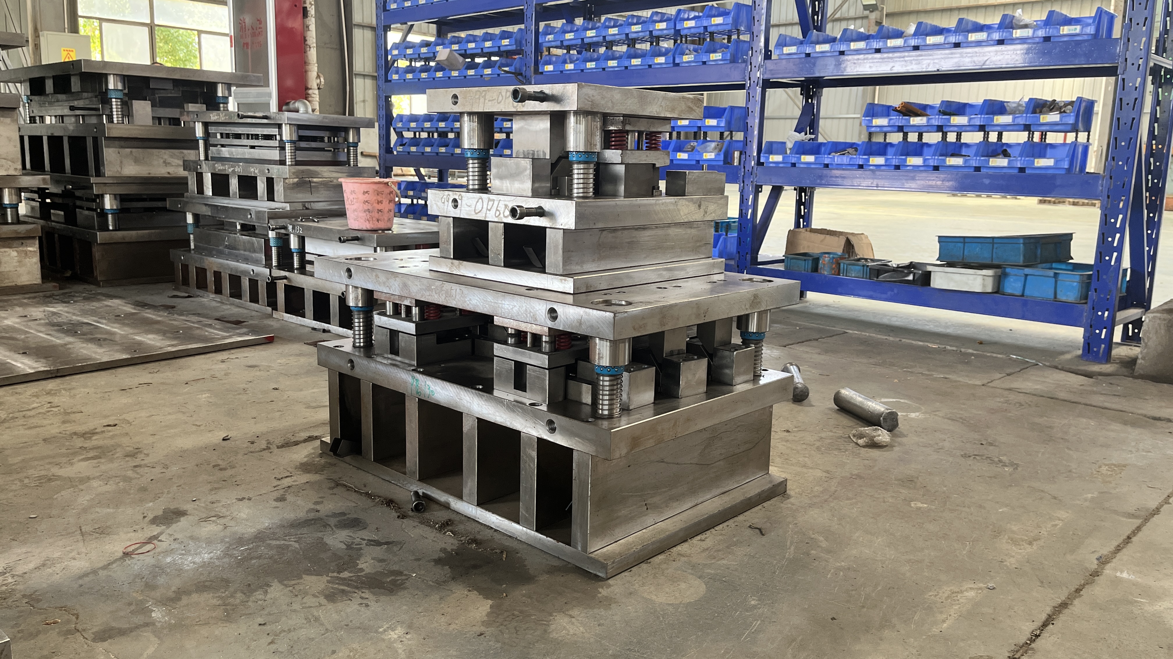
A die, in manufacturing, is a precision tool—usually made of hardened steel—that’s used in a press to cut, form, or shape material to a specific profile. Imagine a cookie cutter, but engineered for metal, plastic, or composite materials and built to withstand thousands or even millions of cycles. So, what is a die used for? In practice, dies are used to produce everything from simple office supplies to complex automotive components, ensuring each part is made to exacting standards.
You’ll hear terms like stamping die, forming die, and progressive die. Here’s how they differ:
- Stamping die: Cuts or shapes sheet metal parts in a press, often in high-volume production.
- Forming die: Deforms material (without removing it) through bending, stretching, or drawing.
- Progressive die: Performs multiple operations at different stations as material advances through the die with each press stroke.
Tool and die fundamentals
To get a handle on what is tool and die, think of “tools” as a broad category that includes anything used to shape, hold, or assemble parts, while “dies” are specialized tools focused on changing the shape of material—usually by cutting or forming. Tool and die work is the backbone of high-volume manufacturing, where repeatability, speed, and accuracy are essential.
So, what is dies in manufacturing? Dies are the engineered components that define the final shape of a product, often working in tandem with presses and other machinery. What is die making refers to the specialized process of designing, machining, and assembling these precision tools, often requiring tolerances as tight as 1/1000 of an inch.
- Blanking: Cutting a flat shape from sheet material.
- Bending: Deforming material along a straight axis.
- Drawing: Pulling material into a die to create complex, often deeper shapes.
- Coining: Applying high pressure to imprint fine details.
- Clearance: The gap between punch and die, critical for clean cuts and tool life.
- Die set: The assembly that holds the die and punch, ensuring alignment.
- Punch: The male component that presses material into or through the die.
- Stripper: Removes the workpiece from the punch after forming or cutting.
- Carrier: Supports and moves the workpiece or strip through multiple stations.
- Station: A specific location within a progressive or transfer die where an operation occurs.
Where die manufacturing fits in the product lifecycle
Die manufacturing sits at the intersection of design engineering and mass production. The process starts with CAD models and design requirements, then moves through material selection, machining, assembly, and rigorous quality checks. Dies are not just tools for cutting or forming—they are the enablers of scalable, repeatable production. In industries like automotive, packaging, and consumer electronics, the quality of the die directly impacts downstream assembly, product quality, and overall cost of ownership.
Die performance is determined as much by design inputs and process sequencing as by machining precision.
Here’s what you’ll learn across this article: clear definitions, a decision matrix for selecting die types, material and heat treatment trade-offs, a step-by-step workflow from CAD to tryout, practical (not fabricated) quantitative considerations, inspection and quality assurance methods, and a troubleshooting framework. Along the way, you’ll find templates and checklists you can copy directly into your own process.
Disciplined die manufacturing isn’t just about making a tool—it’s about building a foundation for lower scrap rates, less press downtime, and a lower total cost of ownership.
Select the right die type with a clear matrix
When you’re tasked with making a new part, picking the right die type can feel overwhelming. Should you use a progressive die, a transfer die, or something else entirely? The choice you make will impact everything from production speed to cost, quality, and even future maintenance. Let’s break down the main types of dies and how to match them to your specific application—so you avoid costly missteps and get the most from your die manufacturing investment.
Choosing the right die type for your part
Imagine you’re holding a print for a stamped metal bracket—do you need high volume, tight tolerances, or flexibility for future changes? Your answers will guide you toward the most effective die architecture. Here’s a comparative look at common die types and their ideal use cases:
| Die Type | Part Complexity | Dimensional Tolerance | Expected Volume | Material Formability | Press Compatibility | Tryout Complexity | Maintenance Intensity |
|---|---|---|---|---|---|---|---|
| Blanking Die | Simple | Moderate | Low to Medium | High | Most presses | Low | Low |
| Progressive Die | Complex, multi-feature | High | High | Good for ductile materials | Requires precise feed and shut height control | High | Medium to High |
| Transfer Die | Very complex, 3D forms | High | Medium to High | Best for challenging shapes | Needs transfer system | High | Medium |
| Compound Die | Moderate | High | Medium | Good | Standard presses | Medium | Medium |
| Forming/Drawing Die | Deep or complex shapes | High | Low to Medium | Requires formable material | Deep-draw presses | High | Medium |
| Coining Die | Fine detail, shallow features | Very High | Medium | Soft or ductile metals | High-tonnage presses | Medium | Medium |
| Extrusion Die | Continuous profiles | High | High | Good for malleable materials | Specialized presses | High | High |
Progressive versus transfer versus compound
Let’s dig deeper into the three most common choices for metal stamping dies:
- Progressive Die: Ideal for high-volume production where each press stroke advances the strip through multiple stations, performing a sequence of operations (punching, bending, forming, etc.). Each station adds a feature, and the part is completed at the end of the strip. This setup maximizes efficiency and material utilization but requires consistent feedstock and careful strip layout. Progressive dies are the go-to for parts with consistent geometry and tight per-part economics.
- Transfer Die: Used when parts must be removed from the strip for free-form operations (such as deep drawing or when multiple forming actions can’t be performed in-strip). Workpieces are mechanically transferred between stations, allowing for more complex shapes but adding to die and press complexity. Choose this when your part geometry can’t be achieved with progressive methods.
- Compound Die: Performs multiple operations (such as blanking and piercing) simultaneously at a single station. This is best for medium-volume runs where part alignment is critical and the geometry is not overly complex.
Forming, drawing, and coining use cases
Forming and drawing dies are crucial when your part requires significant deformation, such as deep cups or complex curves. Coining dies are specialized for imparting fine details or sharp edges, often for decorative or functional features. When selecting press dies or punch press dies, always verify your press’s tonnage and shut height to ensure compatibility with the die set.
Decision tree: Matching your part to the right die
- Start with part geometry: Is it simple (flat/straight) or complex (multiple bends, deep forms)?
- Assess expected production volume: Low, medium, or high?
- Check material type and thickness: Is the material easy to form or does it require special consideration?
- Review tolerance requirements: Are there tight tolerances or critical features?
- Decide:
- If high volume, consistent geometry, and tight tolerances: Progressive die.
- If medium volume, need for combined blank-and-pierce with precise alignment: Compound die.
- If complex 3D forms or operations not possible in-strip: Transfer die.
- If only basic shapes or prototype runs: Blanking or single-station die.
Red flags: When to revisit your die selection
- Excessive burrs or inconsistent features across stations
- Chronic strip misfeeds or jams during production
- Unresolvable springback or dimensional instability
- Press incompatibility with the chosen die set
- Frequent maintenance or premature tool wear
Choosing the right die is about more than just the initial part—it’s about ensuring your die sets and dies and stamping processes deliver long-term reliability, low scrap, and smooth press operation. Next, we’ll explore how your choice of die material and heat treatment can further optimize cost and performance.
Choose die materials and heat treatments wisely
When you’re faced with designing a new metal die or troubleshooting existing forming dies and tools, the choice of die material and heat treatment can make or break your project. Sounds complex? It doesn’t have to be. Let’s walk through the essential considerations so you can balance cost, durability, and performance—without trial and error eating up your timeline or budget.
Tool steel families and trade-offs
Imagine you’re selecting a steel die for a high-volume stamping job. Should you prioritize wear resistance, toughness, or machinability? The answer depends on your application, the properties of the sheet material, and the expected production volume. Here’s a comparative look at common tool steel categories used in die manufacturing, with their key strengths and weaknesses:
| Steel Category | Wear Resistance | Toughness | Chipping/Cracking Resistance | Ease of EDM/Machining | Polishability | Typical Use | Reference Grades/Hardness |
|---|---|---|---|---|---|---|---|
| Cold-work Tool Steels (e.g., 1.2379, 1.2363) |
High (esp. 1.2379) | Good (1.2363 excels) | Moderate | Good | Moderate | General cutting, medium-strength strip | 1.2379: 60–62 HRC 1.2363: 58–60 HRC |
| High-speed Steels (e.g., 1.3343 HSS) |
Very High | Moderate | Good | Moderate | Good | Thick or high-strength sheets | 1.3343: 63–65 HRC |
| Powder Metallurgy Steels (e.g., 1.3344 PM, M V10 PM, M W10 PM) |
Extremely High | Very High | Excellent | Good | High | Max load/edge stability, abrasive or adhesive wear | 1.3344 PM: 63–65 HRC M V10 PM: 61–63 HRC M W10 PM: 66–68 HRC |
| Carbides (e.g., CF-H40S+, CF-H25S+) |
Maximum | Good | Excellent | Challenging | Varies | Maximum wear, high-strength strip | CF-H40S+, CF-H25S+ |
You’ll notice that as wear resistance goes up, toughness often drops. For example, powder metallurgy steels like M V10 PM offer outstanding edge stability for die forming high-strength or abrasive materials, but they come at a higher cost. Cold-work tool steels such as 1.2379 are the workhorses for medium-strength strip, while high-speed steels shine in thick or demanding applications. Carbides deliver unmatched wear life but can be brittle and harder to machine.
Heat treatment and surface engineering
Heat treatment is where die engineering truly tailors performance. By carefully heating, holding, and cooling your steel die, you can dial in hardness, toughness, and resistance to deformation. Most dies are rough-machined before heat treatment and finish-machined after, as hardening can cause dimensional changes. Always reserve a stock allowance for finish grinding post-treatment.
Surface coatings and treatments add another layer of protection, especially against adhesive wear (galling) and abrasive attack. For instance, when forming dies and tools are used on stainless steel, adhesive wear is a common failure mode. Applying a carbide coating or using a steel die with a compatible alloy can dramatically extend tool life (The Fabricator). Powder metallurgy steels are especially suitable for high-temperature coatings due to their stable microstructure and high tempering temperatures.
Material pairing with cutting and forming modes
Choosing the right die material isn’t just about the die itself—it’s about how it interacts with the sheet material, cutting or forming mode, and process demands. Here’s a quick checklist to guide your selection:
- Confirm die material strength matches or exceeds the sheet material’s strength
- Check compatibility of coatings and lubricants with both die and workpiece
- Assess galling risk—especially with stainless or aluminum alloys
- Review press capacity and die components for expected loads and cycles
- Factor in cost of long-term maintenance versus up-front material investment
For example, if your application involves die forming of high-strength steel or abrasive stainless, powder metallurgy steels or carbides can offer the best value over the die’s lifecycle. However, for less demanding applications, a well-chosen cold-work tool steel can provide a cost-effective balance of durability and machinability.
Remember, the right pairing of die material and heat treatment will not only reduce tryout time but also extend maintenance intervals—key levers in cutting costs fast. As you move to the next stage of die engineering, you’ll see how these choices fit into the end-to-end workflow from design to final assembly.

Follow a proven die design and build workflow
When you think about tool and die manufacturing, it’s easy to focus on the finished product—a robust die set ready for high-volume production. But getting there requires a disciplined, end-to-end workflow that minimizes errors, accelerates tryout, and ensures your die assembly meets every performance target. Let’s walk through a practical, step-by-step plan that teams can use to streamline every stage, from initial design inputs to final handoff.
From design inputs to CAD model
Imagine you’re kicking off a new project. The first step is to capture every critical requirement and translate them into a clear, actionable plan. This means reviewing the part print, aligning on GD&T (Geometric Dimensioning and Tolerancing), and confirming all downstream needs. Before any die drawing or CAD work begins, use this checklist to ensure you’re starting with the right data:
- Material type and mechanical properties
- Material thickness and width
- Tolerance stack-up and critical features
- Surface finish and cosmetic requirements
- Press specifications (tonnage, shut height, bed size)
- Lubrication plan (type, application method)
- Expected production volume and lifecycle targets
Once you’ve gathered these details, the next move is to develop a strip layout and station plan—defining how the material will progress through each stage of the die. This step is crucial in die design, as it directly affects material utilization, press speed, and part quality. CAD modeling comes next, where every component—die set, punches, inserts—is modeled in 3D to ensure precise fit and function.
CAM programming and machining strategy
Now, it’s time to transition from digital to physical. CAM (Computer-Aided Manufacturing) programming translates your CAD models into toolpaths for the machining die process. Here, you’ll select strategies for roughing and finishing, define workholding methods, and lock in your datum scheme. Locking datums early is critical: it sets the reference for all future machining and assembly, preventing costly misalignments down the line.
- Rough machining: Remove bulk material to near-net shape, leaving stock for finishing.
- Heat treatment: Harden components for strength and wear resistance.
- Finish machining: Achieve final dimensions and surface finishes, reserving tight tolerances for critical areas.
Throughout, keep a close eye on tool selection and cutting parameters, especially when working with hardened materials or intricate features. Modern die making machines and multi-axis machining centers allow for incredible precision and repeatability, but only if your programming and fixturing are spot-on.
EDM, grinding, and finishing
For features that can’t be milled or turned—think sharp internal corners, deep slots, or fine holes—EDM (Electrical Discharge Machining) is your go-to. Wire and sinker EDM allow you to machine complex profiles in hardened tool steel with exceptional accuracy. Best practices include:
- Maintain proper flushing to remove debris and minimize recast layers.
- Use multiple passes (roughing, then skimming) to achieve mirror-like finishes when needed.
- Plan for minimal heat-affected zones to preserve material properties.
After EDM, surface finishing steps like deburring, honing, and lapping further improve surface quality and dimensional accuracy. Precision grinding is often used for flats, clearances, and critical edges—ensuring your die assembly fits perfectly and delivers consistent results over its lifetime.
Assembly, tryout, and handoff
With all components complete, it’s time for die assembly. This involves careful alignment of the die set, punches, strippers, and guides. Once assembled, the die moves to initial press tryout, where you produce sample parts, check for fit, form, and function, and make iterative corrections as needed. Documentation at each step—capturing changes, measurement results, and lessons learned—creates a valuable feedback loop for continuous improvement.
- Bench and prep all edges, remove burrs, and verify clearances.
- Assemble components following the die drawing and alignment marks.
- Perform initial tryout in the production press; record results and adjust as needed.
- Document final settings, corrections, and inspection results for handoff.
Locking datums early and sequencing heat treat before finish grinding reduces rework and accelerates tryout.
By following this structured workflow, you’ll ensure that your tool and die manufacturing process is robust, repeatable, and ready for high-volume production. Up next, we’ll dive into the quantitative design decisions—like cutting clearances and strip layout—that drive performance and cost savings even further.
Quantitative design decisions that drive performance
When you’re building a stamping press process that actually delivers—minimal scrap, long tool life, and smooth operation—quantitative design decisions are your secret weapon. But what numbers matter most, and how do you use them to your advantage? Let’s break down the core calculations and layout strategies that separate robust die manufacturing from costly trial and error.
Cutting clearances and burr control
Ever noticed how a clean-cut edge from a die press can make the difference between a part that fits and one that fails inspection? That’s the power of proper punch and die clearance. The clearance—the gap between the punch and die—directly affects burr height, edge quality, and tool life. Too tight, and you’ll see cracks or rapid wear. Too loose, and burrs balloon, requiring extra finishing or causing downstream assembly headaches.
- Cutting force: Determined by the perimeter of the cut and the shear strength of the material. (Formula: Cutting Force = Perimeter × Material Thickness × Shear Strength)
- Clearance calculation: According to industry guidelines, the optimal clearance is typically 5–10% of material thickness, adjusted for material hardness and the desired result. For example, for a 1 mm thick steel sheet, a clearance of 0.05–0.10 mm is recommended. Softer materials like aluminum may use slightly less, while harder materials such as stainless steel require more.
- Burr control: Smaller clearance reduces burrs and produces a smoother shear, but may shorten tool life. Larger clearance extends tool life but can increase burrs. Always verify with a tryout and adjust as needed.
- Die formed parts: Drawing operations demand even tighter clearance to prevent tearing or wrinkling in the finished part.
Balancing these variables is a hallmark of effective die process design. Always start with the material’s datasheet and validated industry coefficients, then fine-tune based on real-world results.
Press tonnage, energy, and shut height considerations
Imagine investing in a new die set, only to find your press can’t handle the required force or doesn’t have the right shut height. Press and die compatibility is critical for safe, reliable production.
- Press tonnage: Calculate the maximum force needed—both for cutting and forming—using the formulas above. Always add a safety factor (typically 10–20%) to account for material variation and part complexity.
- Shut height: The distance from the press plate (bolster) to the ram at the bottom of the stroke. Your die set must fit within this, with space for part ejection and safe operation.
- Energy and deflection: Large or complex dies may require more energy per stroke and can cause press deflection if not properly supported. Always confirm your press’s rated capacity and deflection limits before finalizing die design.
When in doubt, consult your press manufacturer’s guidelines and use simulation tools to predict load paths and potential issues before cutting steel.
Strip layout and carrier design
Strip layout isn’t just about material utilization—it’s about stable feeding, reliable part transfer, and minimizing scrap. A well-designed strip and carrier system keeps your die process running smoothly, even at high speeds. Key elements to compare:
| Layout Strategy | Feed Reliability | Scrap Rate | Maintenance Impact |
|---|---|---|---|
| Inboard Carrier | High (strong, stable) | Moderate | Easy to access |
| Outboard Carrier | Good (less robust for thin stock) | Lower (more efficient use of material) | May complicate die maintenance |
| Pilot Locations (early vs late) | Early pilots stabilize feed; late pilots risk misalignment | Depends on strip progression | Early pilots simplify troubleshooting |
| Station Balancing | Even load reduces jamming | Optimizes material use | Balanced stations last longer |
For complex parts or thin stock, consider reinforcing carriers with beads or ribs to prevent buckling. Always plan scrap shedding routes—if scrap can’t fall freely through the die and onto the press plate, you’ll face jams and extra downtime (The Fabricator).
Design for stable feeding, accessible maintenance, and load paths that protect the press and die—these are the pillars of high-performance, cost-effective die manufacturing.
With the right quantitative approach, you’ll see fewer surprises at tryout, longer tool life, and a smoother path from design to production. Next, we’ll examine how disciplined inspection and quality assurance keep those gains locked in through every production run.

Inspection and quality assurance that hold up in production
When you finally reach the stage of running parts through your new die, how do you know the results will stand up to production demands—day in and day out? That’s where disciplined inspection and quality assurance come in. Think of this phase as your insurance policy against costly surprises, rework, and downtime. But what is tool and die work if not a relentless pursuit of repeatable, measurable quality? Let’s break down the essential steps, from planning your checkpoints to documenting every improvement, so your die manufacturing process consistently delivers top-tier results.
Inspection planning and checkpoints
Imagine you’re preparing to validate a new die section. Where should you focus your inspection efforts? Start by mapping out critical features and deciding on the right checkpoints—before, during, and after tryout. Early detection of dimensional inaccuracies or surface flaws can prevent a domino effect of defects downstream. Common checkpoints include:
- First-article inspection after initial tryout
- In-process checks at key stations or after tool adjustments
- Final part inspection before production release
For every die section, ensure your inspection plan covers both the tool itself and the parts it produces. This dual focus helps catch issues like wear, misalignment, or unexpected springback before they impact your bottom line.
Metrology methods that fit the feature
Not all features—or defects—are created equal. That’s why your metrology toolkit should be tailored to what you’re measuring. Here’s a quick-reference table to help you match features to the most effective measurement methods:
| Feature Type | Measurement Method | Typical Tool |
|---|---|---|
| Cut Edges/Burr Height | Comparative gauges, visual inspection, or microscopy | Optical microscope, digital calipers |
| Critical Hole Locations | Coordinate measuring machine (CMM), go/no-go gauges | CMM, pin gauges |
| Formed Radii & Springback | Contour templates, 3D scanning, or optical metrology | Profile projector, laser scanner |
| Surface Finish/Defects | Visual inspection, surface roughness tester | Surface profilometer |
| Die Section Alignment | Dial indicators, laser trackers | Dial indicator, laser alignment tool |
Advanced inspection methods like laser scanning or CT scanning can provide a full 3D map of the die section, revealing subtle deviations or hidden flaws. These technologies are especially valuable for complex progressive dies, where multiple stations and intricate geometries demand high repeatability (Alicona).
Documentation and release
Sounds tedious? Maybe, but thorough documentation is what separates reactive troubleshooting from proactive improvement. Leading manufacturers align their inspection routines with frameworks like IATF 16949 and AIAG PPAP, which emphasize traceability and process discipline. ASME Y14.5 standards guide the interpretation of GD&T for both die and part features, ensuring everyone speaks the same language when reviewing results.
- First-article dimensions meet drawing requirements
- Surface finish is free of critical defects
- Part-to-part repeatability verified across all stations
- Strip alignment and pilot engagement are consistent
- Press condition (energy, shut height) is within spec
- Lubrication system is functioning and consistent
Want to keep your process tight? Use a simple tryout/validation log to document every trial and improvement:
- Trial number
- Changes made (tool adjustments, process tweaks)
- Observed effects (dimensional shifts, surface issues)
- Measurement results (key features, burr height, springback)
- Next action (approve, rework, adjust, or escalate)
By maintaining a short feedback loop between metrology and your CAD/CAM team, you’ll spot trends early and implement design or process changes before issues multiply. This approach not only accelerates production readiness but also builds a traceable record for future troubleshooting or audits.
Disciplined inspection and documentation at every die section are what transform good die manufacturing into great, reliable production—protecting your investment and reputation in the long run.
Next, we’ll explore how a structured maintenance and troubleshooting playbook keeps your dies running at peak performance, shift after shift.
Troubleshooting and maintenance that prevent downtime
Imagine you’re running a busy press line and a single die failure threatens to halt production. Sounds stressful? That’s why a proactive approach to troubleshooting and maintenance is vital for any die maker, tool & die maker, or plant manager focused on reliable, cost-effective die manufacturing. Here’s how to build a playbook that keeps your die equipment running and your schedule on track.
Common failure modes and root causes
When you notice excessive burrs, chipped edges, or misfeeds, it’s a signal that something deeper is wrong. Understanding the most common failure modes—and what causes them—lets you fix issues at the source, not just treat the symptoms. Here’s a structured overview to guide your root cause analysis and corrective action planning:
| Failure Mode | Likely Causes | Corrective Actions |
|---|---|---|
| Cracking | Material lot variation, improper heat treatment, excessive press force | Review material specs, verify heat treat, reduce press load, regrind or replace affected press die parts |
| Chipping | Inadequate die clearance, sharp corners, brittle tool steel | Adjust clearance, round edges, select tougher steel, rehone or regrind |
| Galling / Adhesive Wear | Insufficient lubrication, incompatible die/workpiece materials, high friction | Update lubrication, apply surface coatings, review material pairing, polish die surfaces |
| Abrasive Wear | Stamping abrasive materials, improper coatings, lack of maintenance | Apply wear-resistant coatings, improve cleaning, schedule regular inspections |
| Misfeed | Poor strip alignment, worn guides, incorrect pilot timing | Resquare die set, replace guides, adjust pilot timing, inspect die equipment |
| Burrs | Worn punch/die edges, excessive clearance, improper sharpening | Regrind edges, adjust clearance, follow sharpening best practices |
| Springback Variance | Material property changes, inconsistent forming force, die wear | Review material certification, adjust press settings, refurbish worn areas |
Root cause analysis is more than just fixing what’s broken—it’s about understanding why failure happened so you can prevent it in the future. For complex issues, use visual and microscopic inspection, non-destructive testing, and review of production data to pinpoint the true culprit.
Preventive maintenance planning
Why wait for a breakdown when you can catch problems early? A structured preventive maintenance (PM) schedule is the backbone of effective tool and die making. Here’s a simple template you can adapt to your shop:
- Per Shift: Clean die surfaces, check for visible wear or damage, verify lubrication levels.
- Weekly: Inspect punch/die edges for chipping or dullness, check fastener torque, review strip alignment.
- Monthly: Deep clean die assembly, inspect guides and bushings, verify all safety interlocks on die equipment.
- Quarterly: Full alignment verification, calibrate die set and press, review maintenance logs, photograph wear patterns for records and design feedback.
Regular sharpening, reconditioning, and lubrication are essential. Use the right type of lubricant for your application—oil, grease, or specialty coatings—to reduce friction and extend the life of your press die parts. Don’t forget to document every maintenance action; a detailed log helps your team spot trends and anticipate future needs.
Change control and refurbishment
When a die set needs more than a quick fix—maybe after a major failure or to implement an engineering change—structured change control is key. Always:
- Open a formal work order describing the issue, steps taken, and results
- Prioritize repairs based on production urgency, part quality impact, and available die assembly manufacturer resources
- Schedule repairs to minimize missed cycles and coordinate with production planning
- Share lessons learned and wear pattern photos with engineering to drive long-term improvements
Refurbishment can include regrinding, component replacement, upgrading coatings, or even partial redesigns to address recurring issues. Use data from previous work orders to improve preventive maintenance for similar dies or part families (The Phoenix Group).
Repeatable preventive maintenance and disciplined change logs are the foundation for reducing unplanned downtime, extending die life, and safeguarding part quality—no matter how demanding your production schedule.
With a robust troubleshooting and maintenance system in place, your tool die maker team will spend less time firefighting and more time driving continuous improvement. Next, we’ll help you evaluate die partners and suppliers with the same structured, value-focused approach.
Compare automotive stamping die partners with confidence
When you’re sourcing a new automotive die, the stakes are high—quality, lead times, and cost all ride on your choice of partner. But with so many die manufacturing companies out there, how can you tell which provider truly delivers? Imagine standing in front of a row of suppliers, each promising precision, speed, and value. The real challenge is cutting through the marketing to compare capabilities, certifications, and support on a level playing field—so you avoid costly surprises later.
What to look for in an automotive die partner
Sounds complex? It doesn’t have to be. The best die manufacturer for your project will combine technical expertise, robust quality systems, and transparent communication. Start by asking these key questions:
- Does the provider offer advanced CAE forming simulation to predict and prevent defects before steel is cut?
- Are they certified to IATF 16949 or ISO 9001, demonstrating a commitment to automotive quality standards?
- Do they have in-house EDM, grinding, and metrology capabilities for full control over quality?
- Can they support you from early design reviews through tryout, PPAP, and ramp-up?
- How responsive is their engineering team—do they offer collaborative troubleshooting or just off-the-shelf solutions?
- What is their global footprint and experience with high-volume automotive die programs?
It’s also wise to validate their experience with similar stamping die manufacturing projects and ask for references or case studies. A strong partner will be open to sharing sample CAE reports or walk you through a recent tryout timeline, building trust before you commit.
From CAE to tryout: how capabilities reduce risk
Let’s compare key criteria across top die manufacturers, so you can make an informed, apples-to-apples decision. Notice how early engineering involvement, simulation, and robust quality systems can dramatically cut tryout cycles and reduce total cost of ownership.
| Provider | CAE Forming Simulation | Certifications | In-House EDM/Grinding/Metrology | Collaboration Model | Tryout & PPAP Support | Automotive Experience |
|---|---|---|---|---|---|---|
| Shaoyi Metal Technology | Advanced CAE, virtual tryout, material flow optimization | IATF 16949, ISO 9001 | Full in-house, rapid prototyping to mass production | Collaborative, early structural reviews, formability analysis | Complete PPAP, engineering change support | 30+ global automotive brands, custom stamping die expertise |
| Hatch Stamping Company | Engineering software for process optimization | IATF 16949, ISO 14001 | In-house tool & die, CMM inspection | Hands-on, from design to completion | Die tryout, repair, and engineering changes | 70+ years, automotive and industrial die cutting machine projects |
| Other Die Manufacturers | Varies—often basic simulation or external analysis | ISO 9001 or equivalent | Partial or outsourced; may impact lead time | Standardized or transactional | Support varies; may not offer full PPAP | Experience depends on region and sector |
Why does this matter? Providers leveraging advanced CAE can run virtual die tryouts, predicting springback, thinning, and surface quality before a single part is stamped. This means fewer physical tryout loops, faster time to production, and lower risk of late-stage changes—a huge advantage in stamping die manufacturing for automotive programs (Keysight).
- Ask for sample simulation outputs and CAE reports to validate claims.
- Verify certifications like IATF 16949—don’t just take them at face value.
- Request a tryout schedule and see how issues are tracked and resolved.
- Check if the provider has experience with industrial die cutting machine integration or moulding die manufacturing processes, if relevant to your needs.
Choosing the right tool and die manufacturing company isn’t just about price—it’s about confidence in every phase, from digital simulation to final tryout. The best die manufacturers will welcome your questions and provide transparent documentation at every step.
The most successful automotive die programs start with partners who combine simulation-driven design, robust quality systems, and collaborative support—giving you a clear edge in quality, speed, and cost control.
Ready to put these criteria into action? In the next section, we’ll provide practical checklists and templates you can use to evaluate suppliers and accelerate your die sourcing process.
Templates and next steps to accelerate your die program
When you’re ready to move from theory to action in die manufacturing, having the right resources at your fingertips can make all the difference. Imagine being able to copy proven checklists, logs, and supplier questions directly into your workflow—saving time, reducing errors, and building a more robust process from day one. Whether you’re new to tool & die manufacturing or looking to streamline an established operation, these practical templates and next steps will help you cut costs and boost confidence.
Downloadable checklists and logs
Sounds complex? It doesn’t have to be. The best way to ensure nothing slips through the cracks is to use standardized tools at every stage. Here are text-based templates you can adapt for your own die manufacturing projects:
| Template Name | Purpose | Key Elements |
|---|---|---|
| Die Design Input Checklist | Capture all critical requirements before design begins | Material type, thickness, tolerances, GD&T, surface finish, press specs |
| Press-Selection Checklist | Match die set to the right press | Press tonnage, shut height, bed size, energy, feed type, safety features |
| Strip Layout Review Checklist | Optimize material utilization and feeding reliability | Carrier design, pilot locations, station balance, scrap removal paths |
| Tryout/Validation Log | Track every iteration during die tryout | Trial number, changes made, observed effects, measurements, next actions |
| Inspection Plan Outline | Ensure consistent quality checks at all stages | Feature checkpoints, measurement methods, acceptance criteria, documentation |
| Maintenance Schedule | Keep dies in manufacturing running reliably | Per shift/weekly/monthly/quarterly tasks, lubrication, inspection, documentation |
Align your documentation with standards like ASME Y14.5 for GD&T and IATF 16949 or PPAP for quality planning and traceability. If you’re implementing SMED (Single-Minute Exchange of Die) methods, consider customizing your checklists based on proven templates to further reduce setup times and maximize uptime (SafetyCulture).
Next steps for sourcing and validation
When you’re ready to select a supplier, it’s crucial to move beyond price and look at the full picture. What is a tool and die company if not a partner in your long-term success? Here’s how to approach vendor selection and validation with confidence:
- Use your checklists to compare supplier capabilities, certifications, and technical support.
- Request sample CAE simulation outputs and tryout/validation logs to verify engineering rigor.
- Ask for references or case studies with similar tooling in manufacturing applications.
- Align on documentation expectations—ensure they can meet IATF 16949, PPAP, and ASME Y14.5 requirements.
- Involve your team early in the review process to spot potential gaps or risks.
- For a real-world example of sourcing criteria and capabilities, use Shaoyi Metal Technology’s Automotive Stamping Dies page as a starting point. Their IATF 16949 certification, advanced CAE simulation, and collaborative engineering reviews set a strong benchmark—but always validate claims with direct questions and sample outputs.
Curious about how to make a die that consistently meets demanding specs? The answer is in disciplined process control, clear documentation, and choosing partners who support you from design through production. Don’t hesitate to adapt these templates to your own needs, or to request supplier-specific versions for each new program.
Closing the loop between design, metrology, and maintenance is what transforms great die manufacturing from a one-time success into a repeatable, cost-saving process.
By using these resources and a structured approach, you’ll not only accelerate your next die program but also build a foundation for continuous improvement across the die industry. Ready to put these tools to work? Start by copying the templates above into your workflow—and remember, every robust die program starts with clear requirements, disciplined validation, and the right partners at your side.
Frequently Asked Questions about Die Manufacturing
1. What is a die in manufacturing and what is it used for?
A die in manufacturing is a precision tool, typically made of hardened steel, designed to cut, shape, or form materials in a press. Dies are essential for mass-producing parts with exact shapes and tolerances, such as automotive panels, electronic casings, and more. They ensure consistent quality and efficiency in high-volume production.
2. What are the main types of dies used in manufacturing?
The primary types of dies include blanking, progressive, transfer, compound, forming/drawing, coining, and extrusion dies. Each type is suited for specific part geometries, production volumes, and material requirements. Selecting the right die type is crucial for efficient production and minimizing scrap.
3. How do you select the right die material and heat treatment?
Choosing the right die material involves balancing wear resistance, toughness, machinability, and cost. Common options include cold-work tool steels, high-speed steels, powder metallurgy steels, and carbides. Heat treatment further tailors hardness and durability, while surface coatings can enhance performance, especially for challenging materials or high-volume runs.
4. How is die quality assured during and after manufacturing?
Die quality is ensured through planned inspection checkpoints, tailored metrology methods for each feature, and strict documentation. Techniques like CMM measurement, surface roughness testing, and tryout logs help verify part dimensions, finish, and repeatability. Adhering to standards such as IATF 16949 and ASME Y14.5 ensures reliable, traceable results.
5. What should you look for when choosing a die manufacturing partner?
Key criteria include advanced simulation capabilities (like CAE), relevant certifications (IATF 16949, ISO 9001), in-house machining and metrology, collaborative engineering support, and proven automotive or industrial experience. Reviewing sample reports, tryout timelines, and references helps ensure the partner meets your project’s quality and timeline needs.