 Small batches, high standards. Our rapid prototyping service makes validation faster and easier —

Stamping Die Types And Selection: Cut Scrap, Hit Tolerances
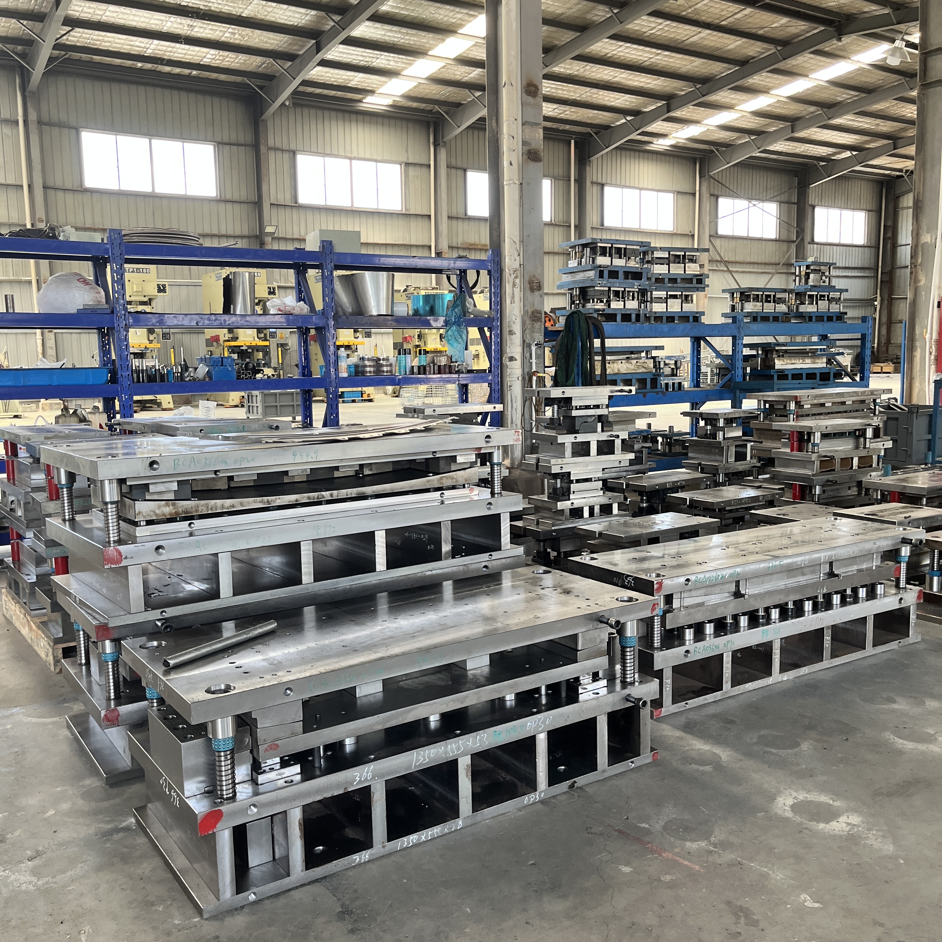
Foundations of the Stamping Die Explained
What is a stamping die and why it matters
Ever wondered how flat metal sheets are transformed into everything from automotive panels to kitchen appliances? The answer lies in the stamping die—a precision-engineered tool at the heart of the sheet metal stamping process. If you’re new to manufacturing, you might ask, what is a stamping die? Or even, what is stamping in the first place? Let’s break it down.
A stamping die is a custom-made tool that cuts and forms sheet metal into a specific shape or profile, using high force delivered by a press. Its working sections are typically made from hardened tool steel or other wear-resistant materials, ensuring accuracy and durability throughout production cycles.
Imagine you’re holding a piece of flat steel. When you press it into a stamping die inside a powerful machine, it comes out shaped, pierced, or trimmed—ready to become part of a car, an appliance, or a bracket. This is the essence of sheet metal stamping: using a die to form, cut, or punch metal into usable parts.
How tool and die work enables the metal stamping process
In manufacturing, the terms tool and die often go hand in hand. The “tool” refers to the overall system that shapes or cuts material, while the “die” is the part of that system responsible for the specific geometry and features of the finished part. The stamping die is mounted in a press—think of it as the muscle—while the die provides the brains, guiding exactly where and how the metal will be shaped or cut. Together, they enable high-speed, repeatable production of complex metal parts.
Throughout the part’s lifecycle, the stamping die is central: from initial prototypes to full-scale production, it ensures every piece is consistent, dimensionally accurate, and meets quality standards. Whether you’re working with a simple bracket or a complex automotive body panel, the right sheet metal die is essential for controlling scrap, hitting tolerances, and keeping costs down.
Core die components and functions
Sounds complex? It helps to break down the stamping die into its key building blocks. Each component plays a unique role in the metal stamping process, ensuring precision and reliability at every cycle. Here’s a quick tour of the most important die components:
- Die Shoe (or Die Plate): The solid foundation that holds all other die components in place. Usually made from steel or aluminum for strength and shock absorption.
- Punch: The part that moves down to cut or form the metal. Punches can be shaped for bending, piercing, or blanking operations.
- Die Section (or Die Button): The counterpart to the punch, providing the opening or cavity the punch enters to shape or cut the metal.
- Stripper Pad: A spring-loaded plate that holds the sheet metal flat and strips it off the punch after cutting or forming.
- Guide Pins and Bushings: Precision components that align the upper and lower halves of the die, ensuring every stroke is accurate and repeatable.
- Springs: Provide the force needed to hold, strip, or form the metal, with options like coil, gas, or urethane springs depending on the application.
- Pilots: Used to precisely locate the sheet or strip within the die, ensuring holes and features are placed exactly where needed.
Each of these parts can be further specialized or adapted for different types of sheet metal die applications, from high-volume automotive runs to short-run prototyping. For a deeper dive into these components and their functions, check out authoritative resources like The Fabricator and Moeller Punch.
Now that you’ve got a clear foundation—what is a stamping die, how it fits into the tool and die ecosystem, and the main die components—you’re ready to explore the different types of dies and how to select the right one for your application. Let’s move on to the next section and map out your options.
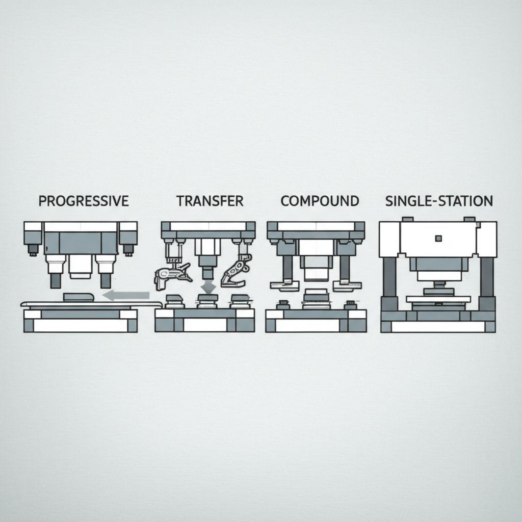
Types of Stamping Dies and How to Choose
Progressive vs. Transfer Dies: Which Fits Your Needs?
When you’re tasked with producing metal parts, choosing the right stamping die can make or break your project’s efficiency and cost. But how do you know which type best matches your part geometry, tolerance demands, and production volume? Let’s break down the most common types of stamping dies and see how each fits into real-world manufacturing.
Progressive Dies are the backbone of high-volume, multi-feature production. In this setup, a continuous strip of metal feeds through a series of stations within the die. Each station performs a specific operation—like piercing, bending, or forming—so by the time the strip reaches the end, your finished part is complete. Progressive die stamping is ideal for:
- High-volume runs (think tens of thousands or more)
- Parts with multiple features or complex shapes
- Consistent, repeatable quality with minimal manual handling
The tradeoff? Progressive dies require significant upfront investment and meticulous design, but they deliver the lowest cost per part at scale. Maintenance is more involved due to the number of moving pieces, but downtime can be minimized with preventative care.
Transfer Dies take a different approach. Instead of the strip feeding through in one go, individual blanks are moved from station to station—either mechanically or with robots. This transfer die stamping method shines when:
- Parts are large, deep-drawn, or require operations that can’t be performed in a single strip
- Complex geometries or multiple orientations are needed
- Medium to high production volumes
While transfer dies offer flexibility for intricate or bulky parts, their setup and operational costs are higher. They’re also more demanding in terms of maintenance, as both the die and the transfer mechanisms require regular attention. But for automotive panels or appliance housings, this method can be the only viable option.
When Compound Dies Are the Right Fit
For flat, simple shapes, compound die stamping might be your best bet. Here, multiple operations—like blanking and piercing—are performed in a single press stroke. This means:
- Low to moderate production volumes
- Parts with simple, flat profiles
- Minimal changeover and quick setup
Compound dies are cost-effective for short runs and prototypes, with less maintenance required due to their straightforward design. However, they’re not suited for complex or multi-feature parts.
Single-Station Dies for Prototypes and Service Parts
Need just a few parts, or working on a new design? Single-station press dies—sometimes called simple dies—perform only one operation per press stroke. They’re perfect for:
- Prototyping and low-volume service parts
- Quick changeovers and maximum per-operation control
While not efficient for mass production, single-station dies give you the tightest control over each step, making them invaluable for development and troubleshooting.
Comparing Stamping Die Types: A Practical Table
| Die Type | Best For | Typical Use Cases | Feed/Handling Needs | Changeover Time | Maintenance Complexity | Scrap Minimization | Process Control | Automation Compatibility |
|---|---|---|---|---|---|---|---|---|
| Progressive Die | High-volume, multi-feature parts | Connectors, brackets, automotive clips | Continuous strip feed | Long (complex setup) | High (many stations) | High (optimized strip layout) | Moderate (depends on die design) | Excellent |
| Transfer Die | Large/complex geometry, deep draws | Automotive panels, appliance housings | Individual blank transfer (mechanical/robotic) | Long (transfer setup needed) | Very High (die + transfer system) | Moderate (depends on blank nesting) | High (per-station tuning possible) | Excellent (with advanced automation) |
| Compound Die | Simple, flat parts, short runs | Washers, gaskets, flat blanks | Manual or strip feed | Short (simple setup) | Low (few components) | High (minimal scrap) | High (one stroke, one part) | Good (for simple automation) |
| Single-Station Die | Prototypes, service parts | Custom brackets, low-volume parts | Manual feed | Very short (quick change) | Very Low | High | Very High (one operation/stroke) | Limited |
How to Choose the Right Die for Your Application
Still unsure? Here are a few decision cues to guide your selection:
- Short run, simple geometry, tighter per-station control: Opt for compound or single-station dies.
- High volume, multi-feature parts with synchronized motions: Progressive dies are your go-to for efficiency and automation.
- Large, deep, or complex shapes, especially with automation: Transfer dies are often the only practical solution.
Remember, your choice of press dies impacts not just production speed, but also scrap rates, maintenance needs, and long-term costs. The right die stamping process ensures you hit tolerances, minimize waste, and keep your operations running smoothly.
Now that you understand the main types of stamping dies and their tradeoffs, you’re ready to dive into the step-by-step workflow for designing and implementing your chosen die. Let’s explore how to move from part intent to a robust, production-ready tool.
Step by Step Stamping Die Design Workflow
From Part Intent to Manufacturable Geometry
Ever looked at a finished metal part and wondered how it goes from a simple drawing to a real-world product? The answer lies in a disciplined stamping die design workflow. This process transforms your part intent—what you want the part to do—into a manufacturable geometry that’s robust, efficient, and cost-effective. But how do you get there without endless trial and error?
Imagine you’re tasked with launching a new bracket for an automotive assembly. You’ll need to start by capturing all requirements: dimensions, tolerances, critical features, and functional intent. This is where Design for Manufacturability (DFM) comes in. By collaborating early with your die tooling and engineering teams, you can spot features that might complicate production, such as tight radii or tricky burr directions. According to industry best practices, small design tweaks at this stage can save significant time and cost later on.
Key DFM checkpoints for sheet metal stamping design include: generous radii to reduce cracking, correct placement of draw beads, well-designed addendum geometry, managing burr direction, and establishing clear datum schemes for measurement.
Strip Layout and Die Type Selection
Once you’ve nailed down the part geometry, the next step is the strip layout. Think of this as the roadmap for how your part will be cut and formed as it moves through the die. The goal? Maximize material usage and production speed while reducing waste. This phase is highly iterative—engineers often go through several concepts before landing on the most efficient layout.
With the strip layout in hand, it’s time to select the die type and station plan. Will you use a progressive die for high-volume runs, or a transfer die for complex shapes? The choice depends on your part’s geometry, expected volumes, and tolerance needs. At this stage, you’ll also define station-by-station operations, ensuring each step in the process is feasible and well-controlled.
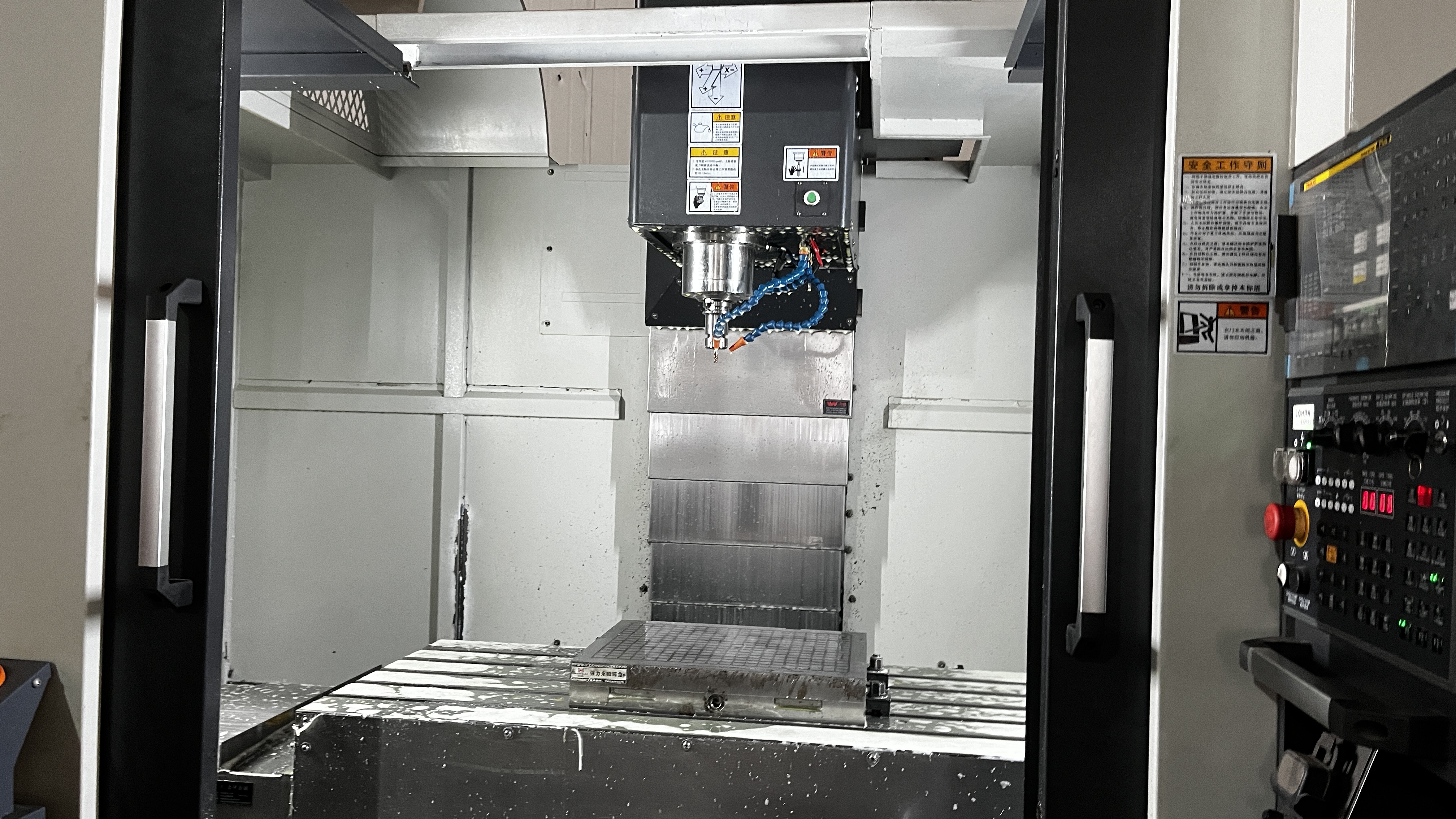
Tool Build, Validation, and Maintenance Planning
With your design validated, you’ll move into detailed metal stamping die design—specifying clearances, radii, die set choices, guides, and piloting features. Sensor strategy and error-proofing mechanisms are built in to catch misfeeds or tool wear before they cause scrap. The next stop is CAM programming and die machining, where digital models become physical components. This is followed by benching, spotting, and pre-tryout checks to ensure everything fits and functions as intended.
Before you launch into full production, dimensional validation and capability studies confirm the die is producing parts within tolerance. Preventive maintenance and a spare parts strategy are set up to keep your die processing reliable over the long haul. Throughout, frameworks like APQP and PPAP provide structure for quality planning, risk management, and documentation (Quality-One).
| Design Phase | Key Deliverables | Responsible Roles |
|---|---|---|
| 1. Capture requirements & critical features | DFM checklist, part print analysis | Product Engineer, Die Designer |
| 2. Material selection & supplier specs | Material data sheet, supplier review | Materials Engineer, Sourcing |
| 3. Strip layout & blank nesting | Strip progression drawings | Die Designer, Process Engineer |
| 4. Die type & station plan | Die selection matrix, station breakdown | Tooling Engineer, Manufacturing Lead |
| 5. Tooling clearance & radii strategy | Clearance tables, radii specs | Die Designer, Quality Engineer |
| 6. Die set, guide, & piloting choices | Assembly drawings, guide pin plan | Toolmaker, Assembly Tech |
| 7. Sensor strategy & error-proofing | Sensor layout, FMEA | Controls Engineer, QA |
| 8. CAM paths & machining | NC programs, machining plans | CAM Programmer, Machinist |
| 9. Benching, spotting, pre-tryout checks | Fit-up reports, dry run logs | Toolmaker, QA |
| 10. Dimensional validation & capability build | PPAP submission, Cpk studies | Quality Engineer, Manufacturing |
| 11. Preventive maintenance & spare strategy | PM schedule, spare parts list | Maintenance, Toolroom |
Following this structured stamping design workflow helps teams reduce costly iteration loops and ensures every die is ready for reliable, long-term production. By integrating DFM, robust strip layout, and disciplined validation, you set the stage for success in both quality and efficiency. Next, we’ll explore how material selection and processing strategies can further optimize your die tooling for specific alloys and applications.
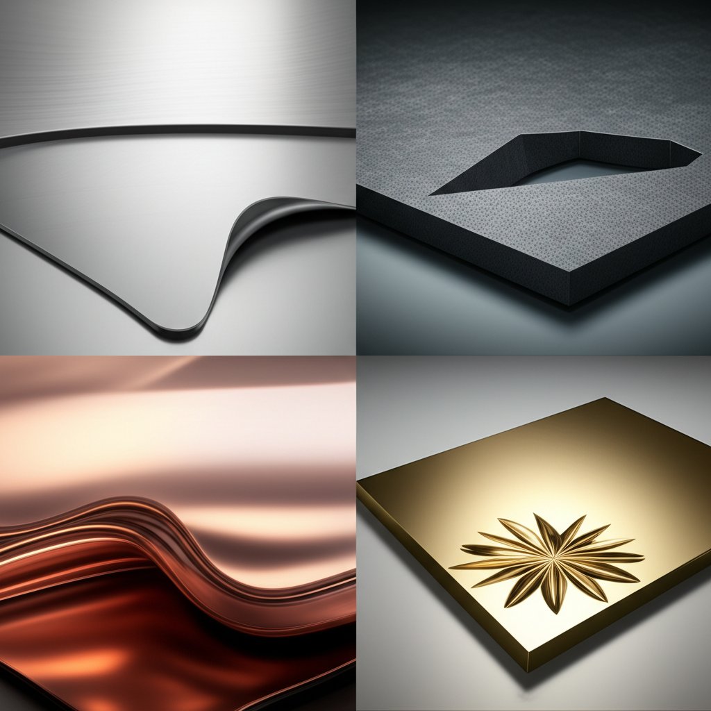
Material Specific Stamping Guidance for Better Tooling
Strategies for Aluminum: Springback and Surface Solutions
When you switch from steel to aluminum in the sheet metal stamping dies world, you’ll notice that the rules change—sometimes dramatically. Have you ever tried to form a deep-drawn aluminum part, only to battle splits and wrinkles? It’s not just you. Aluminum’s formability and surface behavior are unique, and designing your aluminum stamping dies with these in mind is critical for success.
- Springback: Aluminum generally exhibits more springback than soft draw-quality steel. This means after forming, the part wants to “spring” back toward its original shape, making tight tolerances a challenge. To manage this, design your stamped part geometry with generous radii and flowing contours, and anticipate the springback during the die build (The Fabricator).
- Stretchability: Compared to steel, aluminum has lower elongation and tends to stretch in localized areas. For the aluminum stamping process, avoid sharp corners and small radii—these can lead to splits. Instead, use large, gradual radii and gentle transitions in your part and die design.
- Lubrication and Tooling Interface: Although aluminum is soft, it can be surprisingly abrasive due to aluminum oxide on its surface. High-pressure barrier lubricants are essential to prevent galling and premature die wear. Consider coatings or surface treatments on die sections that come into direct contact with the metal.
- Ironing and Finish: If your part allows for ironing (squeezing the metal down a wall to thin it), you can achieve mirrorlike finishes and excellent dimensional control—just like beverage cans.
Approaches for Stamped Steel: From Mild to Advanced High-Strength
Steel remains the most common material in sheet metal pressing and steel stamping dies. But not all steels behave the same. Mild steels are forgiving, while advanced high-strength steels (AHSS) present new challenges in steel sheet stamping applications.
- Clearance and Radii: For ductile steels, use clearances and radii that balance formability and edge quality. As steel strength increases, so does the risk of tool wear and cracking—so increase die clearances and use more generous radii for AHSS.
- Wear and Lubrication: High-strength steels are abrasive. Tool steels with wear-resistant coatings and robust lubrication regimes are crucial for extending die life.
- Blankholder Pressure and Draw Beads: Adjust blankholder force and bead geometry to control metal flow and prevent splits or wrinkles, especially for stamped steel parts with deep draws or complex forms.
- Edge Quality: For all steels, maintain recommended minimum hole diameters and distances from edges to avoid distortion and reduce secondary operations.
Working with Copper, Brass, and Other Alloys
What about conductive or decorative parts? Copper and brass are often used for electrical contacts and aesthetic trim, but they have their own quirks in sheet metal stamping dies:
- Edge Quality: Copper tends to form burrs more easily, so maintain sharp punches and consider secondary deburring.
- Clearance: Brass and copper are softer, so tighter die clearances can improve part precision but may increase tool wear.
- Lubrication: Use compatible lubricants to prevent adhesion and maintain a clean surface finish, especially for electrical applications.
Comparative Table: Material Challenges and Die Strategies
| Material Family | Common Challenges | Recommended Die Strategies |
|---|---|---|
| Aluminum Alloys | Springback, localized splits, galling, surface abrasion |
|
| Mild & High-Strength Steels | Tool wear, cracking, edge distortion, springback (AHSS) |
|
| Copper & Brass | Burr formation, tool wear, surface finish |
|
Choosing the right material and matching your sheet metal stamping dies strategy to its unique properties can dramatically improve first-article success and reduce costly tryout loops. Whether you’re working with aluminum, steel, or copper, understanding these nuances will help you get the most from your die tooling and deliver parts that meet both form and function. Next, let’s dig into how die materials, heat treatment, and coatings further extend tool life and reliability in production.
Tooling Materials, Heat Treatment, and Coatings
Choosing Die Material for Wear and Toughness
When you’re selecting materials for your stamping die, have you ever wondered why some tools last for months while others wear out in weeks? The answer often comes down to the right die material—and understanding the tradeoffs between wear resistance, toughness, and processability. In die for manufacturing, tool steels are the industry standard, prized for their balance of hardness, strength, and machinability. Common choices include high-carbon, chromium, and high-speed steels, as well as cemented carbides for extreme wear applications.
-
Pros of Tool Steel:
- High wear resistance—critical for long production runs
- Good toughness to resist chipping and fracture
- Wide availability and cost-effective for most die manufacturing
-
Cons of Tool Steel:
- Some grades can be difficult to machine or grind
- Improper selection may lead to brittleness or early fatigue
- Careful heat treatment required to avoid distortion or cracking
For high-volume or abrasive applications, powder metallurgy steels and cemented carbides offer even greater wear resistance, though at a higher cost and with more demanding processing needs. The die shoe—the foundation of your stamping die—should also be made from robust, stable materials to absorb shock and maintain alignment of press die components.
Heat Treatment Goals for Stability and Life
Ever noticed how two identical dies can perform differently? Often, it’s the heat treatment that makes the difference. Proper heat treatment transforms the internal structure of your tool and die manufacturing steel, boosting hardness and wear resistance while preserving enough toughness to prevent cracking. Vacuum furnace heat treatment is especially effective, as it eliminates oxidation and decarburization, resulting in a pristine surface and minimal distortion.
-
Benefits of Advanced Heat Treatment:
- Consistent hardness and microstructure for predictable tool life
- Minimal dimensional change—crucial for tight-tolerance die form
- Oxidation-free surfaces, reducing post-treatment finishing
-
Considerations:
- Requires careful process control and expertise
- In-house heat treatment speeds up turnaround but needs investment
- Outsourcing may be practical for small batches or specialty materials
For best results, always coordinate your heat treatment with the die builder and coating supplier to ensure compatibility with subsequent processes and die form requirements.
Coatings and Surface Finishes to Combat Adhesion and Abrasion
Imagine running a die for aluminum and seeing galling after just a few thousand hits. Or forming advanced high-strength steel and struggling with rapid abrasive wear. That’s where modern coatings step in. Surface treatments such as PVD (Physical Vapor Deposition) and CVD (Chemical Vapor Deposition) dramatically extend tool life by reducing friction, blocking adhesion, and resisting wear.
-
Common Coatings:
- TiN (Titanium Nitride), TiCN, AlTiN, AlCrN: High hardness, excellent for abrasive or adhesive wear
- DLC (Diamond-Like Carbon): Ultra-low friction, ideal for aluminum and sticky materials
- CrN/CrC Multilayers: Balanced ductility and hardness for complex die shapes
-
Pros:
- Significantly longer tool life and fewer unplanned stoppages
- Improved surface finish and dimensional stability
- Lower maintenance and regrind frequency
-
Cons:
- Upfront cost and process complexity
- Requires precise surface preparation and heat treatment
- Not a cure-all—must be matched to the application and base material
Wear Issues and Treatment Responses: Quick Reference Table
| Wear Issue | Recommended Treatment/Coating | Notes |
|---|---|---|
| Adhesive wear (galling on aluminum) | DLC, TiCN, or lubricious topcoats | Pair with high-polish and proper lube |
| Abrasive wear (AHSS or high-volume steel) | AlTiN, AlCrN, multilayer CrN/CrC | Use with robust tool steel or carbide |
| Corrosive wear (stainless or coated metals) | CrN, TRD coatings | Consider for harsh environments |
| Edge chipping/brittle fracture | Optimize heat treatment, use tougher die material | Reduce sharp transitions, check die shoe support |
Care and Maintenance Tips for Stamping Die Longevity
Even the best die material and coatings will fail without proper care. To keep your die tooling in top shape:
- Regularly stone and polish working surfaces, following the direction of metal flow
- Adhere to a regrind schedule to maintain edge sharpness and minimize burrs
- Inspect press die components for wear, cracks, or misalignment after every run
- Document all maintenance and repairs to spot trends and prevent repeat failures
By combining smart material selection, advanced heat treatment, and the right coatings, you’ll reduce downtime, control costs, and deliver consistent part quality—no matter your run length or material. Next, we’ll explore how simulation-driven validation can further optimize your die for manufacturing by predicting wear and performance before you ever hit the press.

Simulation Driven Validation for Stamping Dies
Forming Simulation and Springback Prediction
Have you ever spent weeks fine-tuning a stamping die on the press, only to discover that springback or thinning still throws your part out of spec? Imagine if you could spot those issues—and fix them—before cutting the first piece of steel. That’s the promise of simulation-driven validation in today’s stamping technology.
Modern sheet metal forming simulation leverages advanced computational tools (like finite element analysis, or FEA) to predict how metal will behave during the metal stamping process. By running virtual die try-outs, engineers can anticipate common defects such as wrinkles, splits, excessive thinning, and especially springback—where high-strength steels and aluminum alloys tend to bounce back after forming, making tight tolerances tough to hit.
Here’s how a typical simulation-driven workflow unfolds:
- Import robust CAD: Start with a clean, well-dimensioned part model, including clear GD&T (Geometric Dimensioning & Tolerancing).
- Material card selection & boundary conditions: Input accurate material properties and define how the sheet will be constrained and loaded in the sheet metal stamping press.
- Run forming, thinning, and springback analyses: Simulate the full automotive stamping process or other applications, analyzing risk areas for splits, wrinkles, or shape loss.
- Interpret hotspots and adjust die features: Identify problem zones and tweak addendum, draw beads, or reliefs in your die geometry.
- Iterate compensation and validate: Apply predicted springback compensation, then re-simulate and compare with measured parts from tryout or pilot runs.
- Document revisions under change control: Keep a clear record of modifications and their impact on part quality and process capability.
Closing the Loop from FEM to Die Geometry
Why is simulation so transformative for die-stamping machine operations? Because it closes the feedback loop between virtual and real-world outcomes. Instead of costly, time-consuming physical tryouts, you can make digital adjustments—saving material, labor, and downtime. According to industry case studies, simulation not only predicts defects but also helps optimize press force, blankholder force, and lubrication settings, streamlining the entire metal stamping process.
For example, in the automotive sector—where complex shapes and lightweight materials are the norm—simulation allows engineers to validate manufacturability, optimize material flow, and ensure final parts meet strict dimensional and aesthetic standards. Companies like Shaoyi automotive stamping dies suppliers like are now using advanced CAE (computer-aided engineering) tools and IATF 16949-certified workflows to reduce tryout cycles. By running structural reviews and formability analyses early, they cut down on costly press iterations and deliver reliable, production-ready tools faster.
Instrumented Tryout and Digital Validation
But simulation doesn’t stop at the screen. The best results come when you pair digital validation with real-world measurement. During tryout, inline measurement systems and vision cameras on the sheet metal stamping machine provide instant feedback. This data feeds directly into the simulation model, allowing for rapid compensation cycles—so you can dial in the die geometry and process settings with confidence.
Let’s make this actionable. Here’s a table mapping common defects to simulation-guided solutions:
| Defect | Simulation Role | Typical Countermeasures |
|---|---|---|
| Wrinkles | Predicts formation zones & severity | Increase blankholder force, adjust draw bead placement |
| Splits/Cracks | Highlights thinning & stress concentrations | Soften radii, optimize addendum, adjust lube/press speed |
| Springback | Quantifies elastic recovery, guides compensation | Apply die face compensation, change forming sequence |
| Excessive Thinning | Maps strain distribution across part | Modify blank shape, redistribute material flow |
By integrating simulation, inline measurement, and smart compensation, you can dramatically reduce trial-and-error loops and achieve consistent quality—even for the most demanding automotive stamping dies and complex geometries.
Simulation-driven validation is now a must-have for any team aiming to cut scrap, hit tolerances, and keep their stamping die projects on time and on budget. In the next section, we’ll translate digital readiness into real-world reliability with a practical checklist for tryout and commissioning—so your die is press-ready from the very first hit.
Practical Tryout and Commissioning Checklist for Reliable Stamping Die Launch
Pre-Tryout Checks That Save Hours on the Press
When you’ve spent weeks designing and building a stamping die, the last thing you want is press downtime or damaged tooling on launch day. Imagine: you roll your new die up to the stamping die machine, only to find a loose fastener or a misaligned guide pin. Sounds familiar? That’s why a disciplined pre-tryout routine is essential for every die assembly, whether you’re running a single die or complex die sets.
- Verify die assembly completeness: Ensure all press die parts are present and correctly installed. Double-check fastener torque on all mounting bolts and critical connections.
- Check sensors and safety devices: Confirm all die protection systems—like sensors, proximity switches, and whiskers—are installed and operational.
- Inspect sharpness and surface condition: Examine punches, dies, and strippers for edge sharpness, proper edge prep, and clean surfaces. Remove any burrs, debris, or leftover machining marks.
- Dry cycle on the bench: Cycle the die manually to confirm free movement and correct alignment of all moving elements.
- Install in press and set shut height: Carefully position the die in the press, aligning with the press plate and setting the correct shut height. Avoid using press counters; calibrate with setup blocks if needed.
-
Essential Tools and Gauges:
- Torque wrenches for fasteners
- Feeler gauges for clearance checks
- Calipers and micrometers for feature measurement
- Dial indicators for alignment
- Test blanks and certified lube for first hits
- Surface plates for flatness checks
First Hits, Measurement, and Progressive Adjustments
Ready to make your first part? This stage is where careful measurement and methodical adjustments turn a new die into a production workhorse. Here’s how to proceed:
- First-article hits: Run a few test blanks at low strokes per minute (SPM), using traceable material and controlled lubrication. Watch for proper material feed, ejection, and safe operation.
- Measure critical features: Use calibrated instruments to check dimensions, hole locations, and burr direction on the first parts. Record all results for traceability.
- Iterate adjustments: If you spot issues—like misalignment, excess burrs, or improper forming—fine-tune by shimming, spotting, adjusting bead geometry, or tweaking punch-to-die clearances. Repeat as needed until all features hit spec.
| Observed Defect | Possible Cause | Corrective Action |
|---|---|---|
| Wrinkles | Low blankholder force, poor bead design | Increase blankholder pressure, adjust draw beads |
| Splits/Cracks | Sharp radii, excessive thinning, improper material | Soften radii, check material specs, adjust lube |
| Excessive Burrs | Dull punch edge, incorrect die clearance | Regrind punch, reset clearance, inspect die assembly |
| Misaligned Holes | Poor strip alignment, worn pilots | Check pilot condition, realign strip, adjust guide pins |
| Surface Indentations | Debris in die, improper surface prep | Clean die, polish working surfaces, check lube |
Run-In, Capability, and Handoff Criteria
Once your die consistently produces good parts at low speed, it’s time to ramp up and prove stability. Here’s how to close out commissioning:
- Ramp to planned SPM: Gradually increase speed, monitoring heat buildup and part quality. Watch for changes in part dimensions or new defects as speed rises.
- Document acceptance: Record all setup parameters, die settings, and measured results. Create a spare parts list for critical press die parts and wear items.
- Establish handoff criteria: Define the conditions for a successful handoff to production—such as consistent part quality, stable dimensions, and all safety systems functional.
Remember, a structured tryout and commissioning process does more than just prevent costly mistakes—it builds confidence across shifts and ensures every die set is ready for reliable, repeatable production. By using detailed checklists, keeping accurate records, and responding quickly to observed issues, your team can avoid extended downtime and keep your stamping press parts running at peak performance.
With your die assembly validated and press-ready, the final step is ensuring your investment pays off through smart sourcing, ROI modeling, and automation. In the next section, we’ll explore how to select partners and technologies that maximize your return and keep your stamping die operations competitive.
Selecting Partners, ROI Modeling, and Smart Automation for Stamping Die Success
Lifecycle Costing: When Does a Stamping Die Investment Pay Off?
Imagine you’re deciding whether to invest in a new stamping die or stick with your current tooling. It’s not just about the sticker price—real ROI comes from looking at the entire lifecycle. When you break it down, several factors play into your decision:
- Tooling Cost Amortization: Spread the upfront cost of the die over the expected number of parts. High-volume runs justify more sophisticated, durable dies, while short runs may benefit from simpler solutions.
- Expected Maintenance: Durable dies with robust stamping die components require less frequent repairs, reducing downtime and long-term costs.
- Changeover Impacts: Dies designed for quick swaps minimize press downtime—key for flexible, high-mix production.
- Scrap and Quality Costs: Well-designed dies and precise stamping tooling reduce material waste and rework, directly boosting profit margins.
- Automation Compatibility: Investing in automation-ready dies (think coil feeding, servo presses, or robotic handling) increases throughput and consistency, especially in modern industrial stamping environments.
When you factor in these elements, a higher initial investment in a quality die often pays off through lower per-part costs, fewer disruptions, and the ability to scale as your production needs grow.
Selecting Stamping Die Manufacturers: What to Look For
Choosing the right stamping die manufacturer is about more than just price. Imagine you’re sourcing a partner for a critical automotive or electronics project. You’ll want to evaluate:
- Certifications: Look for ISO 9001 or IATF 16949 for automotive work—these signal robust quality systems.
- Engineering Support: Does the supplier offer DFM guidance, prototyping, and collaborative design reviews?
- Technology Stack: Advanced CAE simulation, inline measurement, and digital traceability are must-haves for modern die making industry leaders.
- Production Capacity: Can they handle your volume, complexity, and material needs?
- Onboarding and Communication: Transparent, responsive partners make for smoother launches and fewer surprises.
To help you compare, here’s a table outlining key supplier attributes for stamping die sourcing:
| Supplier | Certifications | CAE/Simulation | Measurement Systems | Engineering Support | Automation Readiness | APQP/PPAP Support | Notes |
|---|---|---|---|---|---|---|---|
| Shaoyi Metal Technology | IATF 16949 | Advanced (full CAE, simulation-to-tryout loop) | Inline vision, digital traceability | Collaborative, DFM, prototyping | High (servo press, robotics, inline inspection) | Yes | Trusted for global automotive projects |
| Die-Matic | ISO 9001 | Modern CAD/CAM, simulation | In-process QC, traceability | DFM, prototyping, custom solutions | Moderate | Yes | Strong in electronics, automotive, and custom assemblies |
| Bopp Busch | ISO 9001 | CAD/CAM, process automation | Sensor-based QC | Design & toolmaking support | High (automation, robotics) | Yes | 75+ years in industrial stamping and automation |
Always validate fit by requesting sample runs, reviewing onboarding processes, and checking references for similar stamping die factory projects.
Smart Automation: Presses, Robotics, and Inline Inspection
Have you noticed how automation is reshaping the die making industry? Integrating smart automation with your stamping die investments can unlock productivity and quality gains:
- Coil Feeding and Servo Presses: Enable fast, precise feeding and flexible stroke profiles for complex parts.
- End-of-Arm Tooling and Robotics: Reduce manual handling, boost throughput, and improve safety—especially for heavy or intricate dies.
- Inline Vision and Measurement: Real-time feedback on part quality allows for immediate adjustments, minimizing scrap and rework.
- Connected Data: Modern stamping die components can include sensors to monitor wear, temperature, and cycle counts, supporting predictive maintenance and reducing unplanned downtime.
By aligning your stamping die investments with automation-ready presses and digital inspection, you position your operation for lower costs, higher uptime, and competitive advantage in both high- and low-volume industrial stamping scenarios.
Selecting the right stamping die manufacturer and automation strategy is a cornerstone of long-term manufacturing success. By focusing on lifecycle ROI, supplier capability, and smart technology integration, you’ll ensure your stamping die projects deliver value from prototype to full-scale production.
Stamping Die FAQs
1. What is a stamping die and how does it work?
A stamping die is a precision tool used in metalworking to cut and shape sheet metal into desired forms. It operates inside a press machine, where the die's components—such as punches and die sections—interact with the metal under high force, enabling repeatable and accurate part production for industries like automotive and appliances.
2. What are the main types of stamping dies?
The primary types of stamping dies include progressive dies, transfer dies, compound dies, and single-station dies. Each serves different production needs: progressive dies excel in high-volume runs with multiple features, transfer dies handle large or complex shapes, compound dies are ideal for simple, flat parts, and single-station dies are best for prototypes or low-volume jobs.
3. How do you select the right stamping die for your project?
Selecting the right stamping die involves evaluating part geometry, production volume, tolerance requirements, and automation needs. Progressive dies suit high-volume, multi-feature parts, while transfer dies are chosen for complex or deep-drawn shapes. For short runs or prototypes, compound or single-station dies offer flexibility and control.
4. What materials are used for stamping dies and how are they treated?
Stamping dies are commonly made from tool steels, high-speed steels, or carbide for wear resistance and toughness. Heat treatment enhances hardness and durability, while surface coatings like TiN or DLC reduce friction and wear, extending die life and improving part quality.
5. How does simulation improve stamping die performance?
Simulation uses computer-aided engineering (CAE) to predict metal flow, springback, and potential defects before physical die manufacturing. This digital validation helps engineers refine die geometry, optimize process parameters, and minimize costly tryout iterations, ensuring higher accuracy and efficiency in production.