 Small batches, high standards. Our rapid prototyping service makes validation faster and easier —

Metal Stamping Dies: Design Rules To Stop Scrap And Rework
Start with the essentials of metal stamping dies
Ever wondered how a flat coil of steel becomes a precise automotive bracket or the frame inside your smartphone? That transformation happens thanks to metal stamping dies—the unsung heroes of modern manufacturing. Whether you’re new to the stamping meaning or a seasoned engineer, understanding the basics is the first step to reducing scrap and rework in your operations.
What metal stamping dies do in production
At its core, a stamping die is a specialized tool that shapes, cuts, and forms metal sheets into repeatable, high-precision parts. Dies are mounted in presses, and when the press cycles, the die’s components work together to cut, bend, or draw features into the metal. This process enables rapid, high-volume production with consistent quality—making metal stamping dies essential for industries like automotive, aerospace, electronics, and appliances.
- Punch: The part that pushes into the metal to cut or form features.
- Die set/plates: The foundation that holds all die components in precise alignment.
- Guide pins: Maintain perfect upper/lower die alignment for consistent results.
- Strippers: Remove the finished part or scrap from the punch after each stroke.
- Pilots: Precisely position the metal strip or blank at each stage.
- Sensors: Monitor part presence, misfeeds, and tool load to prevent costly errors.
How sheet metal stamping transforms flat stock
Imagine starting with a roll of flat steel. The sheet metal stamping process feeds this material into a press, where the die’s punch and die cavity work together to cut, bend, and even draw the metal into complex shapes. Depending on the design, the process might involve:
- Punching (making holes or shapes)
- Blanking (cutting out the basic shape)
- Bending (forming angles and flanges)
- Drawing (stretching the metal into deeper shapes)
- Coining and embossing (adding fine features or logos)
Each operation is controlled by the metal die to keep parts within tight tolerances, minimizing scrap and rework.
Inside the stamping process from coil to finished part
Here’s a typical workflow you’ll find in most stamping operations:
- Receive incoming sheet or coil stock
- Set up the press and load the stamping dies
- Feed material into the die—manually or automatically
- Run progressive, transfer, or single-station operations as needed
- Utilize in-die sensors for real-time quality checks
- Eject finished parts and scrap for downstream inspection
This tightly controlled sequence is what allows stamping to deliver high repeatability and fast cycle times, especially compared to machining or casting. For high-volume runs, the sheet metal stamping process can dramatically reduce per-part costs and maximize material utilization.
- Die set/plates: The main structure holding all components
- Punch: Forms or cuts the metal
- Die cavity: Shapes the part and supports the punch
- Guide pins: Ensure precise movement
- Strippers: Remove parts/scrap
- Pilots: Align material
- Sensors: Monitor process and quality
Die precision isn’t just about part quality—it drives your production rate, scrap levels, and total cost across the entire program.
Why choose stamping over machining or casting?
When you compare metal stamping dies to CNC machining or casting, stamping stands out for its:
- Dimensional repeatability: Each part matches the last, reducing variation
- Shorter cycle times: High-speed presses deliver hundreds or thousands of parts per hour
- Material efficiency: Less waste thanks to optimized strip layouts and minimal machining
While machining can achieve tighter tolerances on complex features, stamping is unmatched for high volumes of simple to moderately complex parts, especially when tight control over thickness and flatness is needed.
What’s next?
Now that you know what is a die in manufacturing and how the basics of stamping work, the next sections will guide you through:
- Choosing the right die type for your part
- Applying design rules to minimize defects
- Selecting and sizing your press
- Tryout and validation for launch success
- Maintenance and troubleshooting strategies
- Material and surface treatments
- Lifecycle economics and supplier selection
Whether you’re an engineer, sourcing specialist, or plant manager, you’ll find practical tips in each section to help you cut scrap, control costs, and get the most from your metal stamping dies.
Choose the right die type with a clear decision path
Ever faced the challenge of picking the best tooling for a new part and wondered, “Which die process will actually save us time and money?” The answer isn’t always obvious—especially with so many types of stamping dies available. Let’s break down the main options, their strengths, and how to match each to your production needs.
Progressive vs transfer vs line dies: What’s the difference?
Imagine your production line as a relay race. In progressive die stamping, the metal strip moves through a series of stations within one die set—each station performing a different operation. This setup is the go-to for high-volume, repeatable parts where speed and integration matter most. Progressive dies can deliver impressive output rates, making them a favorite among progressive die manufacturers for automotive connectors, brackets, and electronic housings.
Transfer dies, by contrast, move individual blanks from station to station—either mechanically or by hand. This method shines for larger or more complex shapes, such as deep-drawn housings or structural panels, where part orientation and multiple forming steps are required. While transfer dies offer superior flexibility, they involve more setup time and higher operational complexity.
Line dies (sometimes called single or stage dies) perform one operation per press stroke and are typically used for low-volume, simple parts or prototyping. They’re straightforward, quick to build, and easy to adjust—but less efficient for high-volume runs.
| Die Type | Part Size & Complexity | Capital Intensity | Tryout Duration | Maintenance Frequency | Scalability | Typical Application |
|---|---|---|---|---|---|---|
| Progressive Die | Small–medium, moderate complexity | High | Medium–Long | Medium | High | Connectors, brackets, high-volume parts |
| Transfer Die | Medium–large, high complexity | High | Long | High | Medium–High | Deep-drawn, structural, or complex shapes |
| Compound Die | Small–medium, simple–moderate | Medium | Short–Medium | Low–Medium | Low–Medium | Flat, high-precision parts |
| Line/Stage Die | Any, simple per stage | Low | Short | Low | Low | Prototypes, low-volume or oversized parts |
Compound and stage tooling use cases
Compound dies combine multiple operations—like blanking and piercing—into a single press stroke. They’re ideal when you need high precision on flat parts but don’t require the complexity (or cost) of a progressive die. Stage or line dies, on the other hand, are best when flexibility and quick changeovers matter, such as in prototyping or when handling a wide range of sheet metal die shapes.
Decision matrix for die selection
- Define part geometry: Is it simple and flat, or complex with deep draws?
- Estimate annual volume: High volumes favor progressive dies; low volumes may justify line or compound dies.
- Assess tolerance and finish: Tight tolerances or cosmetic finishes may require more advanced sheet metal stamping dies.
- Consider secondary operations: Will you need tapping, welding, or assembly in-die?
- Evaluate automation needs: Progressive and transfer dies excel in automated lines.
- Review budget and timeline: Progressive dies require higher upfront investment but pay off in scale; line dies minimize initial cost but limit speed.
Early manufacturability reviews—before you commit to a stamping tool and die—help ensure your die choice matches both part design and production goals. This alignment slashes the risk of late-stage rework and helps you avoid unnecessary scrap or downtime.
Remember, your die selection doesn’t just influence the die process—it shapes everything from press sizing to automation strategy and in-line quality checks. In the next section, we’ll dive into design rules that keep your sheet metal stamping dies running efficiently and defect-free.
Die design rules that prevent defects and rework
Ever noticed how a small design oversight can lead to burrs, cracks, or misfeeds that slow down your line and rack up scrap costs? That’s where smart, practical metal stamping die design makes all the difference. Let’s break down the essential rules that help engineers and sourcing teams get reliable, repeatable results from every die set—no matter how complex the part.
Clearance logic and burr control
Sounds complex? Think of clearance as the tiny gap between the punch and die button. Get it right, and your parts come out clean with minimal burrs. Too tight, and you’ll notice rapid tool wear and possible galling; too loose, and burrs or edge rollover become a headache. The optimal clearance depends on both material type and thickness—harder or thicker materials generally require more clearance to avoid tool damage and excessive force. In practice, always validate your clearance with sample runs or simulation, especially for new alloys or thicknesses.
Corner radii and edge treatments for durability
Sharp corners might look precise on a drawing, but in the real world, they’re stress concentrators. If you’ve ever seen a cracked flange or split edge, chances are the corner radius was too tight for the material or process. Adding generous radii to corners and bends distributes stress, reduces cracking, and improves tool life. Edge treatments—like deburring or coining—can further enhance part durability and cosmetic appearance. When in doubt, use forming simulation or test coupons to validate your sheet metal stamping design before finalizing the die build.
Strip layout, pilots, and progression planning
Imagine your strip layout as the roadmap for material flow through the die. A well-designed strip layout balances station workloads, maximizes material utilization, and ensures consistent feeding. Here are the key strip layout best practices:
- Station balancing: Distribute operations to avoid bottlenecks and uneven wear.
- Carrier design: Maintain strip integrity until the last operation for accurate part location.
- Web width: Leave enough material between parts for strength—too narrow, and you risk misfeeds or jams.
- Slug retention: Plan for reliable slug removal to prevent die damage.
- Scrap evacuation: Design chutes or knockouts to clear waste efficiently.
Don’t forget pilots—these features precisely position the strip at each station, ensuring every hit is on target. For complex parts, progression planning (the distance the strip advances per stroke) is critical to avoid interference and maximize output.
Managing bends, springback, and formability
When you bend metal, it wants to spring back toward its original shape. To compensate, over-bend the part slightly or use coining/restriking in the die. Calculating bend allowance (the extra material needed to account for stretching) is essential—use the material’s K-factor and inside radius to get it right. For deep draws or complex forms, add draw beads or special addendum features to guide material flow and prevent thinning or wrinkling. Whenever possible, validate your sheet metal die design with forming simulations before cutting steel.
Common stamping die components and their functions
- Punch: Forms or cuts the metal into the desired shape
- Die button/cavity: Receives the punch and shapes the part
- Stripper plate: Removes material from the punch after each stroke
- Guide pins/bushings: Maintain precise alignment between die halves
- Pilots: Ensure accurate strip advancement and positioning
- Springs/gas cylinders: Provide return force or cushioning
- Sensors: Detect misfeeds, part-out, or overloads
Design pitfalls to avoid
- Specifying unnecessarily tight tolerances on non-critical features (increases cost and risk)
- Ignoring material grain direction (can cause inconsistent bends or cracks)
- Overlooking slug retention and scrap removal needs
- Failing to provide adequate corner radii or edge relief
- Skipping in-die sensing provisions during the design phase
In-die sensing: Plan it from day one
In today’s high-speed stamping, adding sensors for load, tonnage, part-out, or misfeed detection is no longer optional. Integrate these features into your metal stamping die sets early in the design—not as an afterthought—so they’re robust, maintainable, and can prevent costly downtime or tool damage.
The best stamping die design is proactive, not reactive—anticipate issues with clearance, radii, and strip layout to cut scrap and keep your line running.
With these principles in place, you’ll notice fewer defects, longer tool life, and more predictable production. Next, we’ll look at how to match your die design to the right press, ensuring every detail—from tonnage to shut height—supports your quality and throughput goals.
Press selection that matches die and part geometry
When you’ve designed a robust stamping die, the next critical step is ensuring your press can handle the job—because even the best die will underperform in the wrong machine. Sounds complex? Let’s break it down so you can confidently match your die and part geometry to the right stamping and pressing equipment, avoiding costly mistakes and maximizing uptime.
Estimating tonnage from cut length and forming work
Imagine you’re preparing for a new project. How do you know your sheet metal stamping press has enough muscle? Start by calculating the total tonnage required. To estimate the tonnage required for blanking and punching, use the following formula: Tonnage = Part Circumference × Material Thickness × Material Shear Strength × Safety Factor. For deep drawing operations, use tensile strength instead of shear strength. A safety factor of 1.1 to 1.3 (i.e., an increase of 10-30%) is generally recommended to account for tool wear and fluctuations in material properties. Also, don't forget to factor in the additional forces required by accessories such as springs, ejectors, and gas springs. Remember, having enough tonnage is essential, but you also need to check the press’s available energy, especially for long or multi-stage dies. Insufficient energy can cause jams at bottom dead center and lead to incomplete forming or tool damage (The Fabricator).
Stroke, shut height, and bed size alignment
Ever tried to fit a large die into a small press? It’s a recipe for trouble. The sheet metal die press must have enough stroke length and shut height to accommodate the die stack, material thickness, and any automation. The bed size should support the die’s footprint with room for feeders and scrap evacuation. If the press is too small, you’ll face misfeeds or risk damaging both the die and the stamping die machine. Always verify the shut height (distance from the press bed to the ram at bottom dead center) matches your die’s closed height, and confirm the bolster plate is flat and properly aligned.
Speed, rigidity, and energy delivery considerations
Not all presses are created equal. Mechanical presses deliver high speeds for simpler, shallow parts—great for progressive dies and high-volume runs. Hydraulic presses offer variable stroke and pressure, making them ideal for deep draws or complex forms, though at slower speeds. Mechanical servo presses combine speed with programmable motion, offering flexibility for a wide range of dies and part types. Press rigidity and flywheel energy are crucial—insufficient rigidity or energy can cause deflection, leading to poor part quality and reduced die life. Check that the press can deliver the required energy at the speed you need, and avoid off-center loading which increases wear and misalignment.
- Verify press tonnage and energy meet calculated requirements (add safety factor).
- Check stroke length and shut height against die stack height and feed requirements.
- Confirm bed size supports die footprint and allows for automation or manual feeding.
- Inspect bolster plate flatness and alignment.
- Ensure feeder and lubrication systems are compatible with die and material.
- Review press rigidity and energy delivery for your specific die type.
| Die Type | Compatible Press Features | Typical Speed & Energy Needs |
|---|---|---|
| Progressive Die | Mechanical or servo press, high-speed feeders, moderate stroke, rigid frame | High speed, moderate energy |
| Transfer Die | Hydraulic or servo press, long stroke, programmable slide, transfer automation | Medium speed, high energy |
| Line/Stage Die | Any press type, flexible bed, easy access for manual op or quick changeover | Low–medium speed, low–medium energy |
| Compound Die | Mechanical press, moderate stroke, simple feeders | Medium speed, moderate energy |
Matching your die to the right die-stamping machine is about more than just hitting a tonnage number—it’s about ensuring speed, rigidity, and automation all work in harmony. When everything lines up, you’ll notice smoother runs, less downtime, and better part quality. Next, we’ll walk through how to validate your setup, from prototyping to first-article approval, so you launch with confidence and minimal rework.
Prototyping tryout and validation that de risk launch
When you’re ready to move from design to full-scale production, there’s a lot riding on getting it right the first time. The metal stamping process is fast and efficient, but only if you proactively eliminate surprises—like unexpected cracks, wrinkles, or out-of-spec parts—before production ramps up. Let’s walk through a proven pathway from early prototyping to PPAP-ready launch, so you can minimize rework, scrap, and costly downtime.
Rapid prototyping and soft tooling goals
Imagine you’re launching a new bracket for an automotive assembly. Before investing in hard tooling, you’ll want to validate that your material, part geometry, and forming sequence work as intended. This is where soft tooling, laser blanks, or even 3D-printed dies come in. The goals at this stage are simple:
- Confirm the part’s formability and springback behavior
- Identify potential cracking, wrinkling, or thinning risks early
- Test alternative bead, binder, or addendum designs with minimal cost
- Shorten the learning curve before committing to full stamping die manufacturing
By catching issues now, you’ll avoid expensive tool changes later in the die processing workflow.
Structured tryout with a punch list
Once your hard die is built, it’s time for structured tryout—a critical step in the stamping manufacturing process. The goal? Achieve a stable process that consistently produces parts within spec. Here’s a practical checklist to guide your die tryout:
- Blank size optimization: Adjust blank dimensions to ensure proper draw and minimize edge splits or wrinkles.
- Bead tuning: Fine-tune draw beads or addendum features to control metal flow and prevent thinning or wrinkling.
- Binder pressure: Set and adjust binder force to avoid slips, wrinkles, or part distortion.
- Press speed: Validate the optimal press speed for formability and surface finish.
- Lubrication: Ensure even and adequate lubrication to prevent galling or surface defects.
- Sensor dialing: Test all in-die sensors (misfeed, part-out, tonnage) for reliable operation.
Document every tool change and process adjustment—these records become your roadmap for troubleshooting and process control.
Validation and first-article acceptance criteria
Ready to prove your die is production-ready? First-article inspection (FAI) is your gateway to PPAP approval. Here’s a step-by-step approach:
- Dimensional layout: Measure all critical and reference features against the print.
- Edge/burr assessment: Inspect part edges for burrs, folds, or incomplete cuts.
- Surface finish review: Check for scratches, indentations, or surface strains.
- Material thickness mapping: Ensure uniform thickness, especially in drawn or stretched areas.
- Capability studies (if required): Run short-term capability checks (Cp/Cpk) on key dimensions.
Capture all findings and record the final process settings as ‘frozen parameters’—these become your baseline for ongoing production and audits.
Common tryout symptoms and corrective actions
During tryout, defects can surface—don’t panic. Use the table below to quickly match symptoms to corrective actions, drawing on proven best practices from industry experience and reference sources:
| Symptom | Likely Cause | Recommended Action |
|---|---|---|
| Wrinkles | Low binder pressure, excessive material, improper bead design | Increase binder force, optimize blank size, adjust beads |
| Cracks/Splits | Excessive strain, sharp corners, unsuitable material | Add radii, select more ductile material, optimize die geometry |
| Blanking Burrs | Worn punch/die, excessive clearance, poor lubrication | Regrind punch/die, set correct clearance, improve lubrication |
| Uneven Stretching | Improper blank shape, uneven binder pressure | Adjust blank, balance binder pressure |
| Indentations/Surface Strain | Foreign particles, excessive press speed, insufficient lubrication | Clean dies, optimize speed, ensure proper lubrication |
Validation run: Exposing real-world risks
Before releasing the die to full production, conduct a validation run long enough to reveal issues like thermal growth, lubricant breakdown, or tool wear trends. This run helps you:
- Verify process stability over extended cycles
- Spot gradual shifts in part quality or dimensional drift
- Fine-tune maintenance intervals and lubrication schedules
By following this structured approach, you’ll dramatically reduce the risk of launch delays, costly rework, or customer returns—setting up your metal stamping process for success from day one. Next, we’ll explore how simulation and engineering collaboration can further shorten development cycles and improve quality, especially in demanding automotive applications.

CAE driven automotive dies that shorten tryout
Ever wondered how top automotive brands launch new models with precise, lightweight body panels—yet manage to keep lead times and scrap to a minimum? The secret is out: advanced CAE (computer-aided engineering) and close engineering collaboration are transforming the automotive stamping process. By simulating and refining every detail before steel is cut, manufacturers can avoid costly rework, accelerate launches, and deliver flawless automotive stamping parts at scale.
Formability simulation to predict material flow
Imagine you’re tasked with developing a new door panel from high-strength steel or aluminum. Sounds risky, right? With traditional methods, you’d likely face multiple physical tryouts, unpredictable springback, and late-stage geometry changes. But with CAE-driven formability simulation, you can:
- Predict thinning, wrinkling, and tearing risks before building any physical die
- Visualize how the sheet metal will flow and where defects might emerge
- Optimize blank shape, bead placement, and binder forces virtually
- Simulate springback and adjust tool geometry for accuracy
This virtual approach is especially powerful for automotive stamping dies, where even small dimensional errors can lead to panel fit issues or costly aesthetic defects. As highlighted in industry case studies, sheet metal forming simulation leverages finite element analysis (FEA) to model the complex interactions between material, die, and process parameters—allowing you to catch problems like cracks or excessive thinning before a single part is stamped (Keysight).
Die geometry optimization before cutting steel
When you use CAE early, you’re not just avoiding defects—you’re actively engineering a more robust automotive stamping die. Here’s how the process unfolds:
- Run simulations to identify trouble spots: wrinkling, splits, or potential springback
- Iterate die geometry and addendum features virtually—no wasted steel or rework
- Adjust bead locations, radii, and draw depths to fine-tune material flow
- Integrate structural reviews to ensure the part meets crash and durability requirements
- Validate press force requirements and select the optimal press line
This approach lets you optimize for both manufacturability and end-use performance, all before committing to hard tooling. The result? Fewer physical tryout loops, faster launch, and more consistent custom automotive metal stamping results.
From prototype to mass production without costly rework
So, how does this play out in real-world automotive die cutting? It’s about connecting virtual and physical processes. Start with a CAE-driven prototype to validate formability and springback. Then, as you move to hard tooling, use simulation data to guide tool adjustments, binder pressures, and press settings. Integrate in-depth first-article inspection—often using advanced non-contact metrology—to quickly verify that automotive metal stamped parts meet all dimensional and surface criteria.
Collaboration is key. By involving simulation experts, die designers, and production engineers from day one, you’ll spot design-for-manufacturing issues early and align on realistic tolerances, surface requirements, and process controls. This cross-functional teamwork is what separates top-performing automotive stamping programs from those plagued by delays and rework.
- Define part geometry and critical-to-quality features
- Run CAE simulations to predict risks and optimize die design
- Iterate die geometry and process parameters virtually
- Validate prototype parts for formability and springback
- Transfer learnings to hard tooling and final process setup
- Launch with robust first-article inspection and rapid feedback
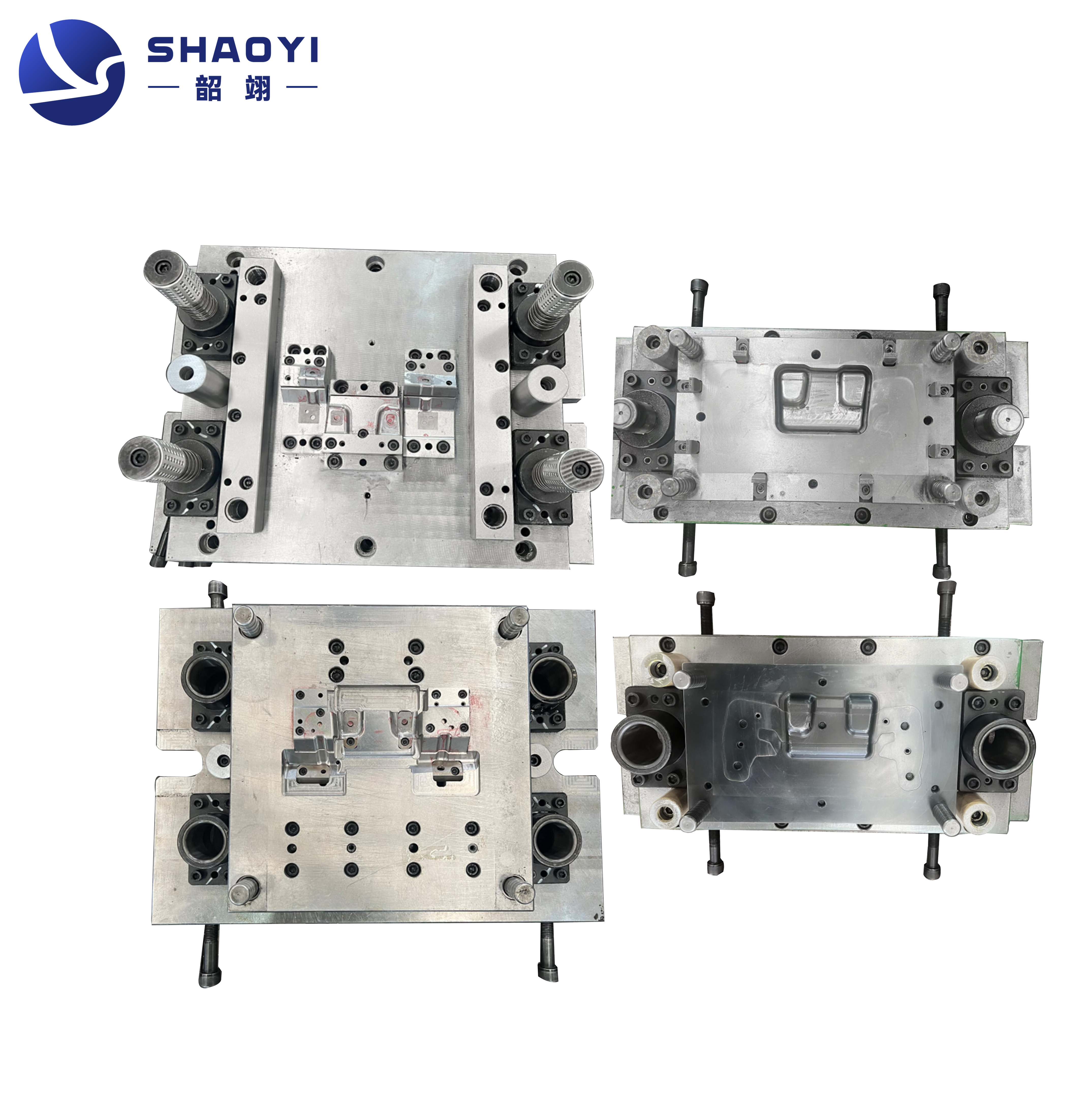
For a real-world example of this approach, see Shaoyi's Automotive Stamping Dies, where IATF 16949-certified processes, advanced CAE simulation, and collaborative engineering are used to optimize die geometry, reduce tryout cycles, and deliver durable, precision components trusted by leading global brands. This CAE-led workflow is quickly becoming the gold standard for custom automotive metal stamping projects where launch speed, dimensional accuracy, and long-term durability are non-negotiable.
Ready to move from simulation to shop floor? In the next section, we’ll explore maintenance strategies that keep your stamping dies running at peak performance, ensuring your investment in simulation and robust design pays off for the entire program lifecycle.
Maintenance strategies that minimize downtime
When you’ve invested in high-quality metal stamping dies, keeping them running at peak performance isn’t just smart—it’s essential for production reliability and cost control. But how do you move from firefighting breakdowns to a proactive, data-driven maintenance strategy? Let’s break down practical steps that keep your sheet metal dies and stamping tooling in top condition, so you can avoid costly surprises and extend tool life.
Preventive maintenance schedules that actually stick
Sounds familiar? You’re in the middle of a critical run, and suddenly a die fails. Unplanned downtime is expensive, but most failures are preventable. The solution: a structured preventive maintenance (PM) program tied to real production metrics—like hits, hours, or cycles. Instead of waiting for issues, schedule regular checks and tasks, such as:
- Punch regrind checks: Restore cutting edges before burrs appear or parts go out of spec.
- Die-set alignment: Ensure upper and lower die halves remain perfectly aligned to prevent part defects and tool wear.
- Sensor calibration: Verify that in-die sensors accurately detect misfeeds, overloads, and part-out conditions.
- Lubrication verification: Apply the correct lubricant, in the right amount, and at the right intervals to minimize friction and wear.
By sticking to a routine, you’ll catch minor issues before they escalate, saving money and extending the life of your metal stamping tooling.
Common wear points and how to monitor them
Imagine your die as a high-mileage car—certain parts naturally wear out first. Focus your inspections on these high-risk zones:
- Cutting edges: Prone to dulling and chipping, leading to burrs and incomplete cuts.
- Draw beads: Wear impacts material flow, causing wrinkles or splits in formed parts.
- Pilots: Excess play or wear can cause misalignment and feeding errors.
- Guide pins/bushings: Worn guides result in die misalignment and uneven part quality.
- Springs and gas shocks: Fatigue or leaks can affect stripper and lifter function, increasing the risk of jams or part ejection failures.
Track leading indicators such as:
- Burr height: Increasing burrs often signal dull punches or misaligned dies—schedule a regrind before scrap rises.
- Alignment drift: Use visual checks and CMM measurements to spot shifts before they cause major defects.
- Tonnage signatures: Monitor press tonnage data for gradual increases, which may reveal die wear or misalignment.
Symptom-to-intervention guide for die maintenance
| Symptom | Likely Cause | Recommended Action |
|---|---|---|
| Rising burr height | Dull punch or die, improper clearance | Schedule punch/die regrind, check and reset clearances |
| Binder marks or surface scratches | Worn draw beads, poor lubrication | Polish or replace beads, improve lubrication type/application |
| Misfeeds or strip misalignment | Worn pilots, guide pins, or bushings | Replace worn pilots/guides, realign die set |
| Increased press tonnage | Die wear, misalignment, insufficient lubrication | Inspect for wear, verify alignment, review lubrication |
| Part ejection failures | Weak springs or leaking gas shocks | Replace springs/gas shocks, check stripper plate condition |
Repair versus rebuild: Making the right call
When your metal forming dies start showing repeated issues, how do you decide between another repair and a full rebuild? Use this framework to guide your decision:
- Cumulative downtime: If repairs are frequent and downtime is rising, a rebuild may be more cost-effective long-term.
- Quality impact: When part quality can no longer meet spec—even after repairs—it’s time to consider a new die or major overhaul.
- Remaining program life: For short remaining runs, minor repairs may suffice; for long-term programs, invest in a rebuild.
- Spare component availability: If critical wear parts are no longer available, a rebuild or new die is inevitable.
Always document each intervention—what was done, why, and the outcome. This traceability accelerates root cause analysis, supports future troubleshooting, and helps you build a data-driven maintenance program.
By turning maintenance into a strategic, well-documented process, you’ll notice fewer breakdowns, higher part quality, and a longer return on your die investment. In the next section, we’ll look at how your choice of die materials, coatings, and surface treatments impacts both durability and total lifecycle cost.
Tooling materials, treatments, and lifecycle planning for metal stamping dies
When you’re faced with a new stamping project, have you ever wondered why some dies last for millions of hits while others wear out after a single campaign? The answer often comes down to material selection, surface treatments, and how you plan for the die’s entire lifecycle. Let’s break down these factors so you can make smart, cost-effective decisions that keep your metal stamping die running longer and more reliably.
Tool steel and coating tradeoffs
Choosing the right material for your steel stamping dies or aluminum stamping dies is about balancing hardness, toughness, and cost. For example, high-speed steel and tungsten carbide are prized for their hardness and resistance to wear, making them ideal for high-volume jobs or when stamping abrasive materials like silicon electrical steel. But, they come with a higher upfront cost. For softer materials, such as stamped steel sheet or aluminum, lower-grade steels may be sufficient and more economical.
Let’s make this more practical. Imagine you’re stamping motor laminations from silicon steel—a notoriously tough material on dies. For example, when stamping highly abrasive materials like silicon steel sheets for electric motors, industry experience suggests that heat-treated D-2 tool steel (hardness RC 60-62) typically produces 2 to 3 million parts before requiring replacement. Under similar operating conditions, for higher production volumes, M-4 high-speed steel (hardness RC 62-64) can achieve a lifespan exceeding 4 million cycles, while cemented carbide (hardness RC 70-72) is expected to exceed 10 million cycles. The material of choice depends on the expected total production volume and the material's wear characteristics. Each step up in hardness and cost should be justified by your production volume and the abrasiveness of the material.
| Material/Coating | Wear Resistance | Toughness | Maintenance Needs | Typical Use Case |
|---|---|---|---|---|
| D-2 Tool Steel (RC 60-62) | High | Moderate | Periodic regrind | Medium production, lamination steel |
| High-Speed Steel (M-4, RC 62-64) | Very High | Good | Less frequent | High-volume, abrasive materials |
| Carbide (CD-260, RC 70-72) | Exceptional | Low (brittle) | Minimal | Ultra-high volume, thin materials |
| Titanium Nitride Coating | Enhances | Maintains base | Extends intervals | Applied over steel or carbide |
| Vanadium Carbide Coating | Maximum | Maintains base | Rarely needed | Carbide tools in extreme wear |
Surface treatments for wear and finish
Wondering how to push die life even further? Surface treatments and coatings are your secret weapon. Techniques like heat treatment, titanium nitride (TiN) coating, and vanadium carbide overlays can dramatically reduce friction, galling, and wear. For example, high-polish finishes on punches and die cavities minimize friction, while lubricious coatings help prevent material from sticking to the die surface.
Modern innovations go even further. Plasma nitriding creates a hard nitride layer for increased fatigue strength and wear resistance. Nanocomposite coatings and self-healing films are emerging to offer even longer service intervals and fewer unplanned repairs. The right combination depends on your specific material, volume, and quality requirements.
Lifecycle and amortization planning
How do you know if a high-end carbide die is worth the investment? It comes down to lifecycle economics. Here’s a simple framework:
- Estimate expected program volume: How many parts will the die need to produce?
- Plan maintenance cycles: How often will you need to regrind, coat, or refurbish?
- Factor in rebuilds or replacements: Will the die need a partial or full rebuild during the program?
- Calculate cost-per-part: Divide the total cost (including maintenance and rebuilds) by the total expected output.
By aligning your die material and treatment choices with your production targets, you’ll avoid overspending up front—or underinvesting and paying for frequent downtime later.
| Evaluation Factor | Build New | Refurbish |
|---|---|---|
| Current Tool Condition | Severe wear/cracks | Minor wear, restorable |
| Quality Metrics | Out of spec, recurring defects | Still meets specs after repair |
| Upcoming Engineering Changes | Major design changes | Minor tweaks or none |
| Production Targets | Long program, high volume | Short run, low volume |
- Assess die’s physical condition and history.
- Check recent part quality and dimensional stability.
- Review planned engineering changes or new requirements.
- Align decision with remaining production volume and timeline.
- Document rationale for build vs refurbish to inform future planning.
Periodic reviews—especially after major runs or changes—help you balance short-term costs with long-term OEE (overall equipment effectiveness) and consistent part quality. By treating die materials, surface treatments, and lifecycle planning as an integrated strategy, you’ll get the most value from every metal stamping die—and minimize costly surprises down the road.
Next, we’ll explore how to compare and select the right die partner, ensuring your supplier’s capabilities and quality systems support your long-term goals for durability, precision, and cost control.
Compare and select an automotive die partner with confidence
When you’re sourcing metal stamping die manufacturers for your next project, the stakes are high—choose the right partner, and you’ll enjoy smooth launches, fewer defects, and scalable support. Pick the wrong one, and you risk missed deadlines, quality issues, or costly rework. So, how do you evaluate stamping die factories and confidently select a supplier who fits your technical, quality, and business needs?
Capabilities and quality systems to verify
Imagine you’re narrowing down a list of stamping dies manufacturers. Beyond just price, what really sets the best apart? Start by checking for globally recognized certifications, such as IATF 16949 or ISO 9001, which signal a commitment to robust quality control and process discipline. Next, review their technical capabilities: do they offer advanced CAE/formability simulation, and can they support your material and complexity requirements? Consider whether they have in-house tryout presses, a broad press range, and the ability to scale up for high-volume runs or adapt to design changes.
| Supplier | Certifications | CAE/Simulation | Tryout Facilities | Press Range | Sample Lead Time | Global Program Support |
|---|---|---|---|---|---|---|
| Shaoyi Metal Technology – Automotive Stamping Dies | IATF 16949 | Advanced CAE, formability, structural reviews | In-house, rapid prototyping to mass production | Wide (small to large automotive panels) | Short (prototyping and PPAP-ready parts) | Trusted by 30+ global brands; engineering collaboration |
| Supplier B | ISO 9001 | Basic simulation, limited automotive experience | Limited; partners with local tryout shops | Small-medium presses | Moderate | Regional only |
| Supplier C | IATF 16949, ISO 14001 | Standard CAE, no structural reviews | In-house tryout, limited automation | Medium-large presses | Long | Some global support |
| Supplier D | ISO 9001 | No CAE, manual design | Outsourced tryout | Small presses only | Long | None |
While Shaoyi Metal Technology – Automotive Stamping Dies stands out for its certification, CAE-led optimization, and global brand trust, remember that the best fit ultimately depends on your part geometry, annual volume, and regional support needs.
Engineering collaboration and CAE depth
Sounds complex? Imagine launching a new model and needing to hit tight tolerances on a lightweight body panel. The right stamping die factory will offer more than just tooling—they’ll collaborate with you from day one, using simulation to prevent defects and reduce tryout cycles. Ask about their engineering team’s experience, their willingness to participate in early design reviews, and their ability to suggest manufacturability improvements. Look for a custom metal stamping die partner who can adapt to material changes, engineering updates, and evolving production targets.
From RFQ to PPAP: Communication standards
When you issue an RFQ, you’re not just asking for a price—you’re setting the tone for the entire partnership. The best stamping dies manufacturer will offer clear, proactive communication, detailed documentation, and transparency at every stage, from quotation through PPAP approval. They’ll set up regular touchpoints, provide written process plans, and document all changes for traceability—making it easier to resolve issues and maintain program discipline.
- Visit each stamping die manufacturer’s facility and review their process documentation.
- Ask for recent customer references, especially in your industry or application.
- Request sample FMEAs, control plans, and tryout reports.
- Clarify how they handle engineering changes and ramp-up support.
- Evaluate their responsiveness and willingness to share technical insights.
Sample RFQ questions to include:
- What certifications do you hold (IATF, ISO)?
- Describe your CAE/simulation capabilities and sample past projects.
- What is your typical sample lead time from PO to first-article?
- How do you support global programs and engineering changes?
- Can you provide references from similar stamping manufacturing projects?
“A thorough supplier evaluation—focused on technical depth, quality systems, and collaborative mindset—sets you up for long-term stamping success.”
By following these structured steps, you can confidently compare stamping die manufacturers, avoid common pitfalls, and select a partner who will support your program from RFQ to PPAP and beyond. In the next section, we’ll wrap up with actionable best practices and checklists to move from concept to production with less scrap and more confidence.
Actionable takeaways to build and run better tooling
Key takeaways for design and launch
When you think about production metal stamping, it’s easy to get lost in the technical details. But what really sets successful teams apart is their ability to turn knowledge into action—consistently, across every launch. So, how do you ensure every die stamp project delivers on quality, cost, and schedule? Here’s a concise roadmap to operational excellence in the die making industry:
- Select the right die type for your part geometry and volume
- Apply proven design rules to minimize defects and extend tool life
- Match press capacity and features to your die and part requirements
- Validate with structured tryout and robust first-article checks
- Build proactive maintenance and refurbishment plans into your workflow
- Align die materials and coatings to your durability and finish targets
- Design in inspection and in-die sensing from day one
- Use simulation and prototyping early to catch issues before production
- Standardize preventive maintenance routines—and document every intervention
Checklist to move from concept to production
Ready to turn strategy into results? Use this cross-functional action list to assign clear ownership and keep your what is die in manufacturing process on track:
- Product Engineering: Define part geometry, key tolerances, and material specs. Document strip layouts and forming simulations.
- Manufacturing Engineering: Select die type, press, and automation. Develop tryout plans and process flows. Prepare maintenance schedules and logs.
- Quality: Establish inspection criteria, FAI/PPAP checklists, and in-die sensor requirements. Review and archive tryout/validation reports.
- Sourcing: Vet suppliers, manage RFQs, and ensure all documentation (FMEAs, control plans, strip layouts) is collected before kickoff.
Save time and reduce errors by building internal templates for strip layouts, tryout checklists, and maintenance logs—these resources help standardize processes and accelerate onboarding for new team members (The Fabricator).
Where to go deeper next
Continuous improvement isn’t just a buzzword—it’s a competitive advantage. After every launch, review production feedback and update your design standards, die stamp checklists, and maintenance routines. Encourage teams to share lessons learned and incorporate new best practices from industry resources or recent projects. By doing so, you’ll not only cut scrap and rework but also build a culture of excellence that keeps your metal stamping dies program ahead of the curve.
Whether you’re new to the die making industry or looking to refine mature processes, these actionable takeaways and tools will help you move from concept to high-yield production—every time.
Frequently Asked Questions about Metal Stamping Dies
1. What is a die in metal stamping?
A die in metal stamping is a specialized tool used with a press to cut, form, or shape sheet metal into precise parts. It consists of components like punches, die sets, guide pins, and sensors, all working together to ensure repeatable, high-volume production with consistent quality. The die's design directly impacts part accuracy, efficiency, and scrap rates.
2. What are the main types of metal stamping dies?
The main types include progressive dies, transfer dies, compound dies, and line (stage) dies. Progressive dies are ideal for high-volume, integrated operations; transfer dies handle larger or more complex parts; compound dies combine multiple operations in one stroke; and line dies are suited for low-volume or prototype work. The choice depends on part complexity, volume, and required precision.
3. What common problems can occur in the metal stamping process?
Common issues include cracks, wrinkles, burrs, uneven stretching, surface indentations, and misfeeds. These problems often stem from improper die design, worn components, incorrect press settings, or inadequate maintenance. Proactive design, preventive maintenance, and in-die sensing help minimize these defects and reduce costly rework.
4. How do you choose the right metal stamping die manufacturer?
Select a manufacturer by evaluating certifications (like IATF 16949), CAE/simulation capabilities, in-house tryout facilities, press range, and global support. Look for transparent communication, collaborative engineering, and proven experience with similar parts. Trusted partners, such as Shaoyi Metal Technology, offer advanced simulation and quality systems to ensure launch success.
5. Why is preventive maintenance critical for stamping dies?
Preventive maintenance extends die life, reduces unplanned downtime, and maintains part quality. Regular checks on cutting edges, alignment, lubrication, and sensors help catch wear or misalignment early. Documenting interventions supports root cause analysis and keeps production running efficiently.