 Small batches, high standards. Our rapid prototyping service makes validation faster and easier —

Stamping Dies, From Basics To Buy-Off: 10 Essential Points
Foundations of Stamping Dies and Why They Matter
What is a Die in Manufacturing?
Ever wondered how a flat sheet of metal becomes a bracket, cover, or complex automotive panel? The answer lies in the die—a custom tool at the heart of the stamping process. In manufacturing, a die is a precision-engineered tool used to cut, shape, or form material, most commonly sheet metal, into a desired profile. Unlike generic cutting or machining tools, stamping dies are designed for repeated, high-precision operations, making them essential for mass production and uniform quality (Wikipedia).
In the world of metal forming, the phrase "what is a stamping" refers to the entire process of transforming sheet metal into finished parts using a die and a press. This method is distinct from machining, which carves away material from a solid block, or casting, which pours molten metal into a mold. Stamping is a cold-forming process—no heat is intentionally applied, though friction can make parts hot to the touch after forming.
How Stamping Works in Sheet Metal
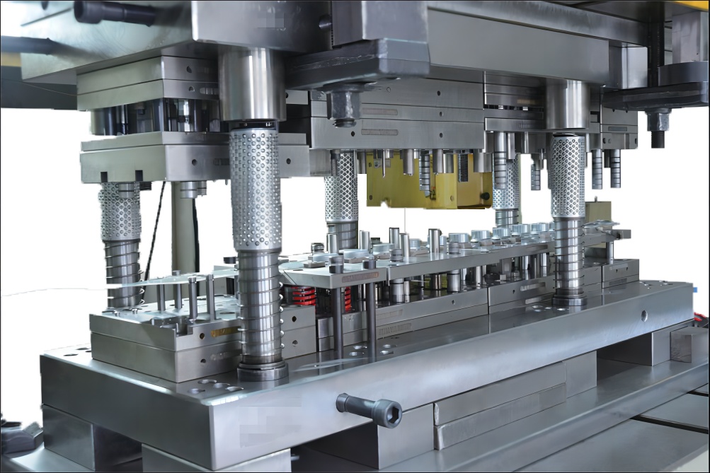
Picture this: a coil or sheet of metal is fed into a stamping press. The press brings the die halves together, guiding and shaping the metal in a split second. The result? Consistent, repeatable parts that meet exacting tolerances. The metal stamping process relies on a careful balance of press force, die design, material properties, and lubrication. If any element is out of sync, you’ll notice issues like burrs, poor fit, or even tool breakage.
To avoid miscommunication between toolroom, production, and engineering teams, it’s crucial to use clear terminology. For example, the “blank” is the initial piece of metal that will be formed, while “strip layout” refers to how multiple parts are arranged in the raw material to maximize efficiency and reduce scrap.
Core Functions of Stamping Dies
So, what do stamping dies actually do? Their main job is to guide and shape sheet metal through a series of precise operations. Here’s a quick rundown:
- Blanking – Cuts out the basic shape from sheet metal
- Piercing – Creates holes or slots in the metal
- Forming – Bends or stretches the metal into a desired contour
- Trimming – Removes excess material for a clean edge
- Restriking – Refines features for improved accuracy or surface finish
Each of these steps may be combined or sequenced differently depending on the part’s complexity. For example, a simple flat washer might only require blanking and piercing, while a structural bracket could go through blanking, forming, trimming, and restriking to achieve its final shape.
Consistent die performance is a system outcome—press, material, lubrication, and maintenance are inseparable from design.
From Concept to Production: The Stamping Die Journey
To help you visualize the typical path a part takes from idea to production using stamping dies, here’s a simplified overview:
- Define requirements and part geometry
- Design the die and plan the stamping process
- Build the die and conduct initial tryouts
- Refine the process for quality and repeatability
- Approve for full production (PPAP or equivalent sign-off)
Understanding this workflow—and the terminology used at each step—reduces confusion and streamlines communication across teams. When everyone shares the same mental model, requirements flow smoothly from engineering through toolroom and into production, minimizing costly errors or delays.
In summary, stamping dies are more than just tools; they’re the backbone of efficient, high-quality metal part production. Grasping the basics of what is metal stamping, how the stamping process works, and what is tool and die ensures you can specify, evaluate, or troubleshoot with confidence, whether you’re in engineering, procurement, or the shop floor.
Die Types and a Practical Selection Matrix for Stamping Success
Progressive vs Transfer Die Selection
Choosing the right die for press operations is not just about the part shape—it's about matching your production needs with the strengths of each die type. Imagine you need thousands of identical brackets every week, or perhaps a few hundred complex covers with deep draws and ribs. The decision you make here will impact your costs, quality, and even how often your line stops for maintenance.
Let’s break down the most common types of stamping dies you’ll encounter in the metal stamping process:
| Die Type | Typical Operations per Hit | Part Handling Method | Best for | Edge Quality | Material Range | Changeover Complexity | Maintenance Load |
|---|---|---|---|---|---|---|---|
| Progressive Die | Multiple (blanking, piercing, forming, trimming, etc.) | Strip fed; part stays attached until final station | High-volume, complex, small-to-medium parts | Good, may require restrike for tight tolerances | Wide (aluminum, steel, some high-strength alloys) | High (complex setup, precise alignment) | High (many stations, close tolerances) |
| Transfer Die | Multiple, with part transferred between stations | Part is separated early and moved by automation | Large, deep-drawn, or intricate parts | Excellent (especially for deep draws) | Broad (including thick or deep parts) | Medium to high (transfer system adds complexity) | Medium to high (mechanical transfer needs upkeep) |
| Compound Die | Multiple (often cutting and punching) in one stroke | Single hit; part removed after each cycle | Flat, simple parts (washers, blanks) | Very good (flatness and clean edges) | Best for mild steel, brass, aluminum | Low (simple setup) | Low (simple design, fewer moving parts) |
| Line Die | Single or few operations | Manual or robotic part movement | Low-volume, large or awkward parts | Variable (depends on design) | Flexible | Low to medium | Low |
| Fineblanking Die | Blanking with controlled edge quality | Precision press and die cutter for metal | Parts needing tight-edge tolerances | Exceptional (smooth, burr-free) | Typically mild steel and select alloys | High (specialized equipment) | High (precision components) |
When Compound Dies Make Sense
Compound die stamping shines when you need flat, simple parts—think washers or blank discs. With a single press stroke, multiple cuts or punches are made, reducing cycle time and labor. If your project needs high repeatability but not complex bends or forms, this method keeps costs low and maintenance simple.
- Pros: Lower tooling cost, fast for simple jobs, easy maintenance
- Cons: Not suited for complex shapes or deep draws
Progressive Dies: High Volume, Complex Parts
Progressive dies are the workhorses for pressing and stamping large batches of intricate parts. As the strip advances through the die, each station adds a feature—bends, holes, forms—until the final part is punched free. The upfront investment is higher, but the per-part cost drops dramatically with scale.
- Pros: Efficient for long runs, supports complex geometry, reduces waste
- Cons: Higher initial tooling cost, more maintenance, not ideal for deep draws
Transfer Dies: Flexibility for Deep and Large Parts
Transfer die stamping is ideal when your part needs multiple operations but can’t stay attached to a strip—think deep-drawn cups or parts with features on all sides. After the first operation, the part is transferred automatically between stations, allowing for unique forming, threading, or knurling steps. This approach supports versatility and is often used for automotive or appliance components.
- Pros: Handles large or deep parts, supports intricate features, reduces secondary ops
- Cons: Slower for high-volume simple parts, transfer system adds cost and complexity
Fineblanking and Tight-Edge Quality
When your part demands a smooth, burr-free edge right out of the press, fineblanking dies are the answer. These dies use a specialized press and controlled clearance to deliver precision edges that often eliminate the need for secondary finishing. However, they require higher investment and are best reserved for parts where edge quality is mission-critical.
- Pros: Exceptional edge quality, minimal finishing required
- Cons: High tooling and press cost, limited to certain materials
Making Your Selection: What Matters Most?
So, how do you choose? Start by considering:
- Part Geometry: Simple and flat? Compound or line dies. Complex or 3D? Progressive or transfer dies.
- Annual Volume: High volume favors progressive dies; low to medium may suit compound or line dies.
- Tolerance and Edge Quality: Tight tolerances or burr-free edges may require fineblanking or additional restrike/coining stations.
- Material Type: Softer metals (aluminum, brass) are easier for most dies; harder materials may need specialized or wear-resistant dies.
- Budget and Changeovers: Consider tooling cost versus per-part savings, and how often you’ll switch jobs.
Remember, the right stamp and die combination is the foundation for efficient pressing and stamping, cost control, and consistent quality. If you’re still unsure, consult with your tooling engineer or a trusted die manufacturer early in your project to avoid costly changes down the road.
Next, let’s explore how to take these choices and translate them into a robust die design workflow that eliminates surprises from concept through production sign-off.
Die Design Workflow from Concept to Production
Requirements Capture and Manufacturability Review
When you start a new stamping die design project, where do you begin? Imagine you’re tasked with developing a custom bracket for an automotive assembly line. Before anyone starts modeling or cutting steel, the first—and most critical—step is gathering clear, actionable requirements. This means reviewing part drawings, tolerances, GD&T (Geometric Dimensioning and Tolerancing), expected production volumes, and the chosen material. At this stage, Design for Manufacturability (DFM) is essential. You’ll want to ask: Are there tight radii, deep draws, or features likely to wrinkle or tear during the stamping manufacturing process? Getting everyone on the same page—engineering, procurement, and toolmakers—avoids costly surprises down the road.
- Checklist for Requirements Gate:
- Is the latest part print available and reviewed?
- Are tolerances and critical features clearly identified?
- Has the material and thickness been confirmed?
- Are production volume and press specs defined?
- Has DFM feedback been incorporated?
Blank Development and Strip Layout
Next up is blank development—the process of defining the starting shape (blank) that will be formed into the final part. This is where sheet metal stamping dies come into play. The strip layout arranges multiple parts along the coil or sheet, balancing material utilization with process reliability. You’ll notice that an efficient strip layout can save significant material costs and reduce scrap in production metal stamping. This step is iterative; it often takes several concepts and digital simulations to land on the optimal layout.
- Checklist for Strip Layout Gate:
- Does the layout minimize scrap and maximize feed length?
- Are pilot holes and carrier designs included for accurate progression?
- Is the layout compatible with press bed size and coil width?
- Are all forming, piercing, and trimming stations logically sequenced?
Progressive Die Layout and Detailed Drawings
Once the strip layout is locked, attention shifts to the detailed metal stamping die design. This involves 3D modeling and 2D drawings for every punch, die button, stripper plate, and guide pin. Each component must be specified for material, hardness, and fit. At this point, you’ll also plan for springback compensation—especially if the part features bends or forms that might relax after forming. The Bill of Materials (BOM) and detailed station planning ensure nothing is overlooked before the build begins.
- Checklist for Design Gate:
- Are all die components modeled and checked for interference?
- Have springback and overbend strategies been validated?
- Are all fasteners, lifters, and sensors specified?
- Is the BOM complete and reviewed?
Build, Tryout, and Buyoff
With drawings approved, the die moves into the build phase. Modern shops use CNC machining, grinding, and EDM to craft precise components. Once assembled, the die undergoes tryout—initial runs in the press to validate function, part quality, and repeatability. Adjustments are made to address issues like burrs, misfeeds, or springback. Only after passing all checks is the die approved for production release.
- Checklist for Tryout and Buyoff Gate:
- Does the die produce parts within spec, with no splits or wrinkles?
- Are all sensors and safety features tested and functional?
- Has a capability study (e.g., Cpk) been completed?
- Is documentation (work instructions, maintenance guides) finalized?
No-Go Condition: If split risk in deep draws remains unresolved after tryout, halt production and revisit the blank shape or die geometry before proceeding.
End-to-End Workflow: From Concept to Production Release
- Requirements and DFM review (tolerances, GD&T, volumes, material)
- Risk assessment (identify features likely to wrinkle or tear)
- Blank development and strip layout
- Station planning and carrier design
- Springback strategy and compensation
- Detailed 2D/3D drawings and BOM preparation
- Build plan and key milestones
- Tryout plan and loop closure for issues
- Documentation and approval for production release
This structured approach to stamping design aligns all stakeholders, minimizes costly rework, and sets clear acceptance criteria at every gate. By following each step, you ensure your sheet metal stamping design is robust, efficient, and ready for high-volume production metal stamping without surprises.
Ready to see how digital tools can make this workflow even faster and more reliable? Next, we’ll explore simulation, CAD/CAM, and PLM integration for modern die design.

Simulation and the CAD CAM PLM Digital Thread
CAE for Formability and Springback Prediction
When you’re designing stamping dies, how do you know the sheet metal will form as intended—without wrinkles, splits, or excessive springback? This is where Computer-Aided Engineering (CAE) simulation steps in. Using forming simulation software, engineers can quickly assess whether a proposed die design will create defects like thinning, wrinkling, or tearing before any steel is cut. For example, metal forming simulation tools allow you to predict blank shape, springback, and formability risks, so design changes can be made early—saving both time and material.
Imagine you’re tasked with a deep-drawn automotive panel. Instead of relying on trial and error with expensive prototypes, you run a simulation to check for areas prone to cracking or excessive thinning. The results highlight problem zones, letting you adjust die geometry or process parameters before moving to the next phase of die processing. This not only shortens development time but also increases ROI for high-volume manufacturing.
FEA for Die Components and Inserts
But what about the die itself? That’s where Finite Element Analysis (FEA) comes into play. FEA breaks down complex die assemblies into small elements, simulating how each part will respond to the forces of the stamping process. You’ll see how punches, die plates, and inserts handle stress, helping prevent premature failure or unexpected wear.
Picture a critical die insert that must withstand repeated impact in a high-speed die-stamping machine. FEA lets you check if the insert’s material and geometry are up to the task, or if changes are needed to avoid cracks and downtime. This virtual testing also supports better decisions about material selection and heat treatment, further optimizing tool and die manufacturing for longevity and reliability.
CAD/CAM Strategies for Quicker Build
Once your design is validated through CAE and FEA, the workflow shifts to CAD (Computer-Aided Design) and CAM (Computer-Aided Manufacturing). CAD models define every feature and fit, while CAM turns those models into precise toolpaths for CNC machining die components. This digital handoff eliminates manual translation errors and speeds up die assembly, ensuring that every detail—down to the smallest punch or lifter—is built exactly as intended.
Modern die manufacturing leverages integrated CAD/CAM platforms, making it easier to iterate designs, simulate machining steps, and verify NC (Numerical Control) code before cutting steel. The result? Fewer mistakes, faster turnaround, and a smoother path from design to production.
PLM for Revision Control and Traceability
Sounds complex? It’s actually more manageable thanks to Product Lifecycle Management (PLM) systems. PLM acts as the digital backbone for tool and die manufacturing, connecting every stage of the process—from initial material data to final NC files and production feedback. It ensures that everyone works from the latest design, tracks every change, and maintains a single source of truth for all die processing activities (SME.org).
With PLM, you can:
- Collaborate seamlessly across engineering, manufacturing, and quality teams
- Maintain revision control and traceability for every die component
- Quickly update designs based on tryout feedback or process changes
- Reduce costly errors from working on outdated files
This digital thread—from concept to final part—reduces silos, boosts efficiency, and helps you spot workflow gaps before they become bottlenecks.
- Material data
- Forming simulation (CAE)
- Geometry compensation
- FEA for die components
- Tool design (CAD)
- CAM (machining die components)
- NC verification
- Tryout feedback
- PLM updates and revision control
If reference materials provide validated material cards, use them; otherwise, document assumptions and build correlation loops at tryout.
In summary, integrating CAE, FEA, CAD/CAM, and PLM in a single digital thread transforms die manufacturing from a series of disconnected steps into a streamlined, data-driven process. This approach not only speeds up die assembly and reduces risk but also ensures that your die-stamping machine delivers consistent, high-quality parts—every time. As you move forward, consider whether your current workflow leverages these digital best practices, or if there are opportunities to close gaps and drive even greater efficiency in your next project.
Next, we’ll break down the key calculations and strip layout strategies that underpin robust, cost-effective stamping tooling.
Calculations and Strip Layout Made Practical for Stamping Dies
Tonnage and Energy Calculations: Sizing Your Stamping Tooling
When you’re planning a new sheet metal die press or choosing from metal stamping die sets, the first question is: How much force will your operation require? Underestimating tonnage can damage equipment; overestimating leads to unnecessary costs. Here’s how to get it right:
Blanking Force ≈ Perimeter × Thickness × Shear Strength
For bending operations, especially in air forming or the coining process, the die opening directly impacts tonnage. A widely used formula for air bending is:
Tonnage per inch = [(575 × (Material Thickness)2) / Die Opening] × Material Factor × Method Factor / 12
- Material Factors: Mild steel (1.0), Copper (0.5), H-series aluminum (0.5), T6 aluminum (1.28), 304 stainless (1.4)
- Method Factors: Air forming (1.0), Bottom bending (5.0+), Coining (10+)
Multiply the result by the length of the bend to get total tonnage. Always check your press and metal stamping tool limits before proceeding.
Bend Allowance and Deduction: Getting Flat Patterns Right
Ever wonder why your finished part doesn’t match the print? It’s often due to inaccurate bend calculations. When you stamp sheet metal, each bend stretches the material, requiring precise compensation in your flat blank.
Bend Allowance (BA) = [(0.017453 × Inside Bend Radius) + (0.0078 × Material Thickness)] × Complementary Bend Angle
To find the Bend Deduction (BD):
Bend Deduction = (2 × Outside Setback) - Bend Allowance
Where Outside Setback = tan(Bend Angle / 2) × (Material Thickness + Inside Bend Radius). Adjusting for these values ensures your sheet metal stamping process produces parts that fit every time (The Fabricator).
Springback and Overbend Strategies: Compensating for Material Memory
Springback is the tendency of metal to partially return to its original shape after bending. Ignoring this leads to angles that are too shallow or parts that won’t assemble. So, how do you plan for it?
- Know your material: High-strength steels and aluminum tend to have greater springback than mild steel.
- Increase overbend: Design the die to bend slightly past the target angle, so when it springs back, it lands at the correct value.
- Use simulation: Modern CAD/FEA tools can predict springback for your exact geometry and material, reducing trial and error.
For the coining process, where the punch penetrates deeply into the material, springback is minimized but tool wear increases. In most stamping tooling projects, a balance between overbend and die life is key.
Strip Layout and Material Utilization: Nesting for Efficiency
Material costs can make or break your project. That’s why strategic strip layout—how you arrange parts on the sheet—is essential in every sheet metal stamping process. A smart layout can boost utilization rates above 85%, while poor nesting wastes thousands in scrap.
- Feed Direction: Align parts with the grain when required for strength.
- Pilot Locations: Place pilot holes for accurate strip advancement and registration.
- Web Width: Maintain enough material between parts for strength, but minimize to reduce scrap.
- Slug Control: Design for safe ejection and containment of scrap slugs.
- Scrap Rate: Use nesting software or heuristics (like Bottom-Left Fill or Largest First) to minimize waste.
For irregular shapes, allow rotation and clustering of parts with complementary curves. Automated software can test thousands of layouts in seconds, but even manual methods can achieve strong results with careful planning.
Summary Table: Key Relationships in Stamping Calculations
| Parameter | Key Formula/Rule | Design Implication |
|---|---|---|
| Tonnage (Blanking/Bending) | Perimeter × Thickness × Shear Strength or [(575 × t2)/V] × Factors |
Right-sizing press and die set |
| Bend Allowance | BA = (π/180) × bend angle × (inner bend radius R + K factor × material thickness T) | Accurate flat blank size |
| Springback | Material property + Overbend strategy | Die geometry compensation |
| Strip Layout | Nesting heuristics, web width, pilot holes | Material utilization, process reliability |
Die clearance should be selected as a percentage of material thickness, with higher clearances for harder or thicker materials. For example, mild steel may use 5-10% of thickness, while stainless or high-strength alloys may require more. Always consult material and tooling standards for specifics.
By mastering these calculations and layout principles, you’ll ensure your stamping tooling delivers quality, cost-effective results from the first part to the last. Next, let’s see how material choices further shape die design, affecting everything from edge quality to tool life.
Material Choices and Their Impact on Die Design
Designing for High-Strength Steels
Ever tried to bend a thin branch versus a thick, stiff one? That’s the challenge with high-strength steels in stamping dies. These materials—such as dual-phase, high-strength low-alloy, and bake-hardenable steels—are increasingly common in automotive and appliance industries, but they come with unique demands. Compared to mild steel, high-strength grades have less stretchability, more springback, and can become brittle after forming.
When working with steel stamping dies or stamped steel parts, you’ll notice:
- Clearance: Higher clearances are needed to minimize tool wear and avoid excessive burrs.
- Bend Radius: Use larger die entry radii—often six to eight times the material thickness—to prevent cracking.
- Springback: Expect greater springback. Overbend strategies or simulation-driven compensation are essential.
- Tooling: Premium tool steels and advanced coatings reduce galling and wear from abrasive high-strength alloys.
- Lubrication: Choose high-performance lubricants to maximize metal flow and keep tooling cool.
Ignoring these factors can lead to splits, excessive burrs, or rapid die wear, making early feasibility reviews critical for any steel sheet stamping project.
Aluminum Forming Pitfalls and Cures
Switching to aluminum? The aluminum stamping process promises lightweight, corrosion-resistant parts but introduces its own set of challenges for aluminum stamping dies. Aluminum is more ductile but prone to galling (material transfer onto the die) and requires careful strip layout and die surface finishes.
For stamped sheet metal in aluminum:
- Clearance: Slightly higher than mild steel to avoid edge tearing and minimize galling.
- Bend Radius: Aluminum tolerates smaller radii, but too tight a bend can still cause cracking—aim for 1–3 times the thickness.
- Springback: Moderate, but still requires compensation in die design.
- Coatings: Use hard coatings (like TiN or DLC) on die surfaces to reduce galling and improve die life.
- Lubrication: Apply specialist lubricants designed for aluminum forming.
Don’t overlook grain direction—bending across the grain reduces the risk of cracking. For complex shapes, simulation and careful process planning are your best allies.
Edge Quality and Burr Control by Material
Edge quality is a direct result of how well die design matches the material’s properties. Whether you’re producing stamped metal brackets or precision stamped steel covers, the right clearance and maintenance plan make all the difference.
| Material Family | Die Clearance | Min. Bend Radius | Springback Tendency | Preferred Coatings | Lubrication Needs |
|---|---|---|---|---|---|
| Mild Steel | 5–10% of thickness | = Thickness | Low | Standard nitrides | Standard forming oils |
| High-Strength Steel | Higher than mild steel | 6–8 × thickness | High | Premium tool coatings | High-performance, extreme pressure |
| Stainless Steel | 10–15% of thickness | 2–4 × thickness | High | Hardened, polished | Specialty lubricants |
| Aluminum | 1–3 × thickness | = Thickness (or slightly larger) | Moderate | Hard, low-friction (TiN/DLC) | Aluminum-specific, anti-galling |
Note: Use qualitative guidance where standards vary; always validate with a trial or simulation for critical applications.
- Galling Mitigation: Regularly polish die radii and apply coatings to reduce material transfer, especially with aluminum and stainless steel.
- Draw Bead Tuning: Adjust bead geometry and placement to control metal flow for high-strength or thick materials.
- Restrike Strategy: Use restrike stations for parts needing tight edge tolerances or improved surface finish, particularly in stamped steel parts.
- Tool Maintenance: Monitor burr height and burnish zones to schedule timely die sharpening, preventing excessive burrs and maintaining edge quality.
Material-driven die design isn’t just about making parts—it’s about making them right, with maximum tool life and minimal rework. Early collaboration and simulation are the best insurance for robust, cost-effective results.
As you plan your next project—whether it’s a run of aluminum brackets or high-strength stamped sheet metal components—remember that each material family demands its own die design strategy. Up next, see how modern presses and automation factor into these decisions for even greater efficiency and consistency.
Modern Presses, Automation, and Industry 4.0 in Stamping Dies
Servo Press Profiles and Forming Stability
When you walk onto a modern stamping floor, you’ll notice the hum of servo presses replacing the clatter of older die press machines. Why the shift? Servo-driven sheet metal stamping press systems offer programmable force, speed, and position profiles—giving engineers the power to fine-tune every hit. Imagine forming a deep-drawn aluminum part: with a servo press, you can slow the ram at critical points, reducing wrinkling and splits, then accelerate through less sensitive steps for higher throughput. This level of control is a game-changer for both forming stability and die longevity.
Unlike traditional mechanical or hydraulic presses, servo presses eliminate clutches and flywheels, reducing energy consumption by 30–50%. They also enable quick changeovers between jobs, making them ideal for flexible, high-mix production environments. The result? Consistent part quality, less tool wear, and a dramatic reduction in downtime—especially valuable in industrial stamping operations where every minute counts.
| Technology | Design Impact | Outcome |
|---|---|---|
| Servo dwell profiles | Allows ram to pause at bottom dead center | Reduces wrinkling, improves forming consistency |
| Programmable speed/force | Adapts to material and part geometry | Minimizes splits, optimizes cycle time |
| Real-time diagnostics | Continuous monitoring of force, position, and speed | Early detection of die wear or misalignment |
| Energy-saving mode | Motor idles when inactive | Cuts power use, lowers operating costs |
| Vibration and temperature sensors | Integrates with predictive maintenance systems | Prevents unexpected breakdowns, extends die life |
Automation and Part Handling in Transfer Systems
Automation is the backbone of high-speed stamping and pressing operations. Transfer systems—robotic arms, conveyors, or in-press transfer rails—move parts between stations without human intervention. This not only boosts throughput but also ensures consistent part orientation and minimizes handling damage.
For complex parts or when using a multi-station sheet metal press die, automation controls cam timing, lifter velocity, and part ejection. The right settings reduce the risk of jams and misfeeds, protecting both the die and the press plate. In advanced transfer lines, servo-driven automation can adapt in real-time to part position or process changes, further reducing scrap and downtime.
Sensing and Industry 4.0 for Tooling Health
Here’s where Industry 4.0 takes center stage. Smart sensors embedded in the die and press continually monitor key parameters—force, position, vibration, temperature, and even lubricant condition. Data flows to cloud-based analytics, enabling predictive maintenance and adaptive process control. That means you can spot a worn punch, a misaligned guide, or overheating stamping press parts before they cause costly downtime.
- Tonnage sensors: Monitor press force for overloads or tool wear
- Stripper travel sensors: Detect incomplete part ejection or misfeeds
- Misfeed/short feed sensors: Alert operators to material advancement errors
- Temperature sensors: Warn of overheating in critical die or press components
Industry 4.0 also enables digital twins—virtual models of the die and press system—so you can simulate changes, optimize cycles, and validate new setups before running physical parts. The integration of IoT devices and cloud analytics empowers teams to make data-driven decisions on maintenance, process tweaks, and even inventory planning.
Design the die to be ‘sensor friendly’—clear routing, protected mounting, and serviceable connectors.
Bringing It All Together: Practical Implications for Die Design
So, what does all this mean for you as a die designer or process engineer? It means every new industrial stamping project should consider:
- Servo press compatibility—can your die take advantage of programmable profiles?
- Automation integration—are lifters, cams, and transfer rails coordinated for smooth part flow?
- Sensor access—are critical points easy to monitor and maintain?
- Data connectivity—does your press and die supply actionable data for predictive maintenance?
By designing with these elements in mind, you’ll improve uptime, reduce maintenance costs, and deliver higher part quality—no matter how demanding the application. Next, we’ll walk through inspection and maintenance templates to ensure your dies keep performing at their best, shift after shift.
Inspection Acceptance and Maintenance Templates for Stamping Dies
FAI Checklist and Acceptance Criteria: Setting the Standard
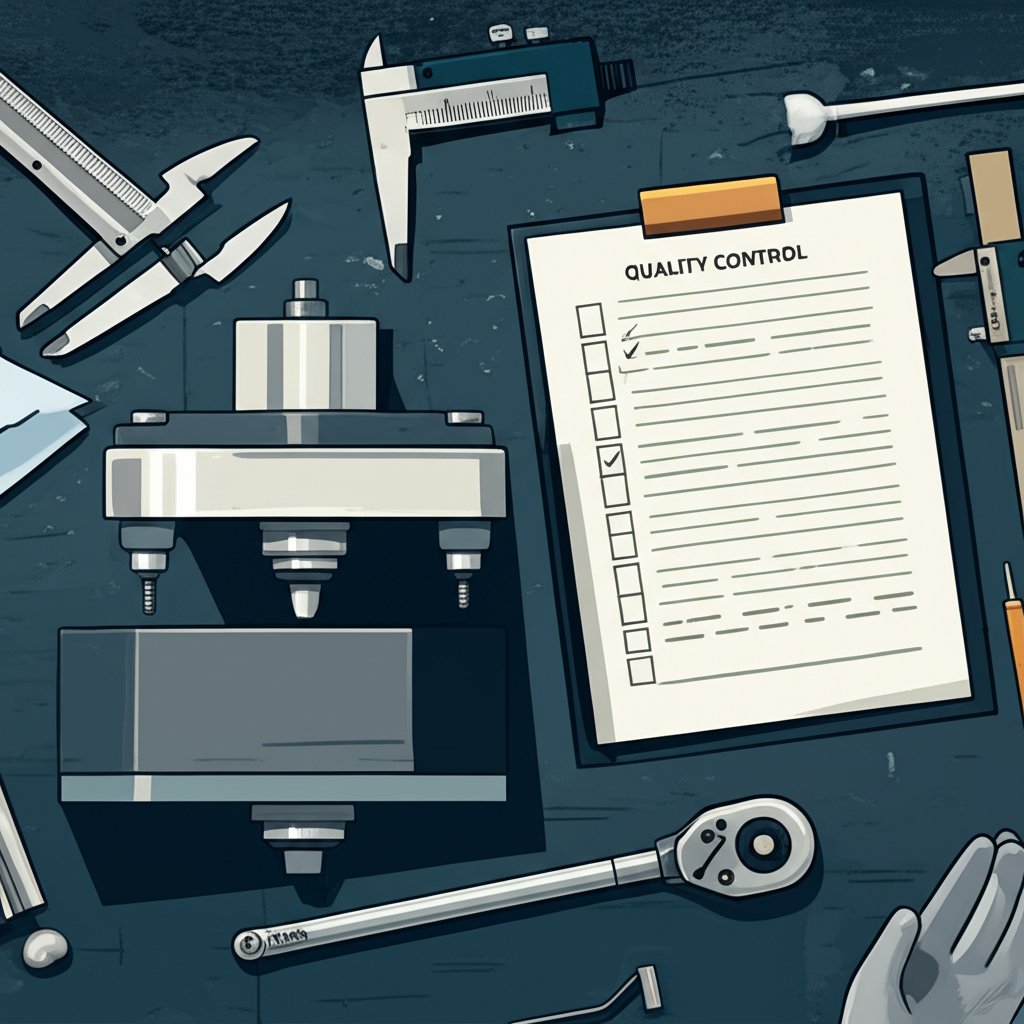
When you launch new stamping die components or make changes to existing tooling dies, how do you know your process is ready for production? That’s where First Article Inspection (FAI) comes in—a structured approach that ensures every stamped part meets design and customer requirements before ramping up volume. Think of FAI as your quality gatekeeper: it verifies that your sheet metal dies, processes, and documentation are all aligned from the start (SafetyCulture).
Imagine you’re preparing for an FAI on a new bracket. Here’s a sample checklist structure that covers what matters most:
| Characteristic | Method | Nominal/Tolerance | Gauge | Sample Size | Result (Pass/Fail) |
|---|---|---|---|---|---|
| Hole diameter | Caliper | 10.00 ± 0.05 mm | Mitutoyo Digital Caliper | 5 | Pass |
| Bend angle | Protractor | 90° ± 1° | Angle Gauge | 5 | Pass |
| Material thickness | Micrometer | 2.00 ± 0.03 mm | Starrett Micrometer | 5 | Pass |
| Surface finish | Visual/Ra Meter | ≤ 1.2 μm Ra | Surface Tester | 2 | Pass |
This table format helps teams quickly spot non-conformances and assign corrective actions. Each row should link directly to a ballooned drawing reference, ensuring nothing gets missed during dies manufacturing or review.
- Gage R&R readiness: Confirm measurement system capability for all critical dimensions.
- Master part: Select a representative stamped part from the first production run.
- Cavity balance (if applicable): For multi-cavity sheet metal dies, check uniformity across all cavities.
- Capability study: Gather data for process capability (e.g., Cp, Cpk) to demonstrate repeatability.
Acceptance criteria are typically pass/fail—if a characteristic is out of tolerance, document the deviation and trigger corrective action before moving forward (3D Engineering Solutions).
Process Capability and Runoff Planning: Ensuring Repeatability
After FAI, capability runs and runoff planning prove that your tooling dies can consistently produce stamped parts within spec. This step involves running a set quantity (often 30–300 parts) and analyzing dimensional data for trends, outliers, or process drift. If the process is stable and all results are within tolerance, you’re ready for production sign-off.
Key documentation includes:
- Dimensional reports for each stamping die component
- Attribute checks (e.g., part marking, surface quality, packaging)
- Process capability indices (Cp, Cpk)
- Corrective action records for any out-of-tolerance findings
For most dies tool applications, it’s best practice to keep these records organized and accessible for audits or customer reviews. Digital templates and checklists streamline this process, reducing paperwork and approval time.
Preventive Maintenance Intervals and Tasks: Keeping Dies Tooling at Its Best
Once your dies are in production, preventive maintenance (PM) is your best defense against unplanned downtime and costly repairs. Imagine the impact if a punch cracks or a stripper plate misaligns mid-shift—production halts, and scrap rates spike. A structured PM schedule ensures your tooling dies stay in top condition, maximizing tool life and part quality.
- Per-shift checks: Clean die surfaces, lubricate moving parts, remove debris, inspect for obvious wear
- Weekly checks: Examine punch wear, check stripper and pressure pad alignment, verify fastener tightness
- Monthly checks: Inspect guide pins/bushings, check spring fatigue, review shims and die alignment
- Refurbish vs. replace: If wear exceeds acceptable limits or cracks appear, refurbish or replace the affected stamping die components promptly
Regular inspection and preventive maintenance are the backbone of reliable dies manufacturing—catching small issues early prevents costly downtime and extends tool life.
By standardizing your FAI, process capability, and PM routines, you’ll achieve faster approvals, fewer escalations, and higher repeatability for every batch of stamped parts. Up next, discover how to choose the right stamping die partner—one who can support you from prototype through production and beyond.
How to Select the Right Stamping Die Partner for Your Project
Vendor Selection Criteria That Prevent Surprises
When you’re ready to move from design to production, choosing among stamping die manufacturers can feel overwhelming. Imagine investing months in a new product, only to face delays, quality issues, or communication breakdowns with your die supplier. How do you avoid these pitfalls? The best approach is to use a structured evaluation process that considers not just price, but engineering expertise, technology, certifications, and long-term support. Here’s what to look for:
- Engineering Depth: Does the stamping dies manufacturer offer in-house tool and die design, simulation, and process optimization?
- Simulation Capability: Can they run CAE/FEA studies to predict material flow and springback before cutting steel?
- Certifications: Look for IATF 16949 or ISO 9001—these signal robust quality systems, especially for automotive stamping dies.
- Production Capacity: Can the stamping die factory scale up to meet your volume, or do they specialize only in prototypes or short runs?
- Launch & Support: Will you get help with tryout, PPAP, and troubleshooting after delivery?
- Transparency: Is pricing clear and communication proactive, with documented processes and regular project updates?
- Reputation & Experience: Check references, site visits, and regulatory history to validate claims.
- Value-Added Services: Do they offer assembly, packaging, or logistics support to streamline your supply chain?
What to Look for in CAE and Tryout Capability
The difference between a smooth launch and costly rework often comes down to a partner’s technical resources. Progressive die manufacturers that leverage advanced CAE simulation can predict forming issues and optimize die geometry before manufacturing begins. This reduces the number of tryout loops, shortens lead times, and improves first-part quality. For high-volume or complex projects, ask potential suppliers:
- What simulation software do you use for custom metal stamping dies?
- How do you validate simulation results with actual tryout data?
- Do you provide detailed tryout reports and support for PPAP or customer audits?
- Can you demonstrate successful launches for parts similar to yours?
| Partner | Engineering Services | Certifications | Simulation Capability | Launch & Support | Reputation |
|---|---|---|---|---|---|
| Shaoyi Metal Technology | Full tool & die design, advanced CAE/FEA, formability analysis, rapid prototyping, mass production | IATF 16949 | Comprehensive CAE simulation, geometry optimization, tryout reduction | In-depth structural review, launch support, global project experience | Trusted by 30+ global automotive brands |
| ATD | Tool & die design, prototyping, engineering support, value-added services | IATF 16949, ISO 14001 | Modern software, in-house expertise, tryout and process optimization | On-site support, transparent project management, long-term partnership | Strong customer retention, positive industry feedback |
| Other Metal Stamping Die Manufacturers | Basic tool & die, some engineering, limited simulation | ISO 9001 or none | May use basic simulation or rely on experience | Support varies, often limited after delivery | Reputation varies, check reviews and references |
Balancing Cost, Lead Time, and Risk
It’s tempting to choose the lowest quote, but hidden costs—delays, rework, or quality escapes—can quickly erase any savings. Start by outlining your priorities: Is your timeline aggressive? Is part complexity high? Do you need a partner for ongoing production or just a single project? Then, weigh the trade-offs:
- Cost: Lower upfront cost may mean less engineering depth or limited support.
- Lead Time: Shops with in-house simulation and flexible capacity can often deliver faster, with fewer tryout cycles.
- Risk: Certified, experienced partners reduce launch risk and improve long-term results.
For critical applications like automotive stamping dies, it’s worth investing in a die metal stamping manufacturer who can demonstrate success with similar parts and volumes. Remember, your supplier is not just a vendor—they’re a strategic partner in your product’s success.
Choosing the right stamping die manufacturer is about more than price—it's about finding a partner whose engineering, technology, and support match your needs, now and for the future.
As you finalize your decision, revisit your checklist and compare options side by side. A transparent, well-documented process will help you select a stamping dies manufacturer who can deliver quality, reliability, and peace of mind from prototype to production. Next, we’ll wrap up with actionable takeaways and a resource guide to support your stamping projects from start to finish.
Actionable Next Steps and Trusted Resources for Stamping Die Success
Key Takeaways for Design and Launch
As you reach the end of your stamping die journey, you might be asking: What truly sets a successful project apart? After reviewing each stage—from requirements capture and simulation to inspection and partner selection—several core principles stand out. Whether you’re new to stamping die manufacturing or refining your next metal stamping die project, these lessons can help you avoid common pitfalls and deliver consistent results:
"Every successful stamping die is the product of clear requirements, early risk assessment, robust simulation, and a collaborative approach from design to production. Skipping any step can lead to costly rework, missed deadlines, or quality escapes."
- Align all stakeholders early—engineering, procurement, and toolroom must share the same mental model.
- Use simulation (CAE/FEA) to catch forming, springback, and die stress issues before building the sheet metal die.
- Prioritize material-driven design choices for durability and part quality.
- Integrate automation and data monitoring for uptime and process control.
- Standardize inspection and preventive maintenance to maximize tool life.
- Select a partner with proven expertise in stamping die manufacturing, CAE capability, and IATF/ISO certification.
Your Next Steps Checklist
Ready to move from theory to action? Here’s a prioritized checklist you can use for your next custom metal stamping die or automotive stamping die launch:
- Requirements Alignment: Confirm all specs, tolerances, and volumes with stakeholders.
- Early CAE/FEA Simulation: Run digital forming and die stress checks to de-risk design.
- Strip Layout Optimization: Iterate for best material use and robust progression.
- Calculation Pack: Finalize tonnage, bend allowance, and springback compensation.
- Press & Automation Review: Validate die compatibility with press, transfer, and sensor systems.
- First Article Inspection (FAI) Plan: Prepare documentation, gage R&R, and acceptance criteria.
- Preventive Maintenance Schedule: Set intervals for cleaning, inspection, and sharpening.
"What is tool and die work? It’s the disciplined process of turning requirements into reality—one that rewards preparation, teamwork, and a commitment to quality at every stage."
Trusted Resources to Support Your Stamping Projects
Looking for further support or a partner who can guide you from concept to production? If your project demands CAE-driven optimization, IATF 16949 certification, and a proven track record in automotive stamping die launches, consider exploring Shaoyi Metal Technology’s custom stamping die solutions. Their approach—leveraging advanced simulation, in-depth engineering collaboration, and global experience—aligns with the best practices outlined throughout this guide.
Remember, the right partner can make all the difference—whether you’re sourcing a single stamping die or building a long-term supply chain for complex assemblies. Use the checklists, principles, and resources above to drive your next project to a successful buy-off and beyond.
Frequently Asked Questions About Stamping Dies
1. What is a stamping die and how does it work?
A stamping die is a precision tool used in manufacturing to cut, form, or shape sheet metal into specific parts. It operates within a press, where metal is fed between die halves that guide and shape it through processes like blanking, piercing, forming, and trimming. This method enables high-volume, consistent production of uniform metal components.
2. What are the different types of stamping dies?
There are several main types of stamping dies: progressive dies (for complex, high-volume parts), transfer dies (for large or deep-drawn items), compound dies (for simple, flat parts), line dies (for low-volume or large shapes), and fineblanking dies (for parts requiring exceptional edge quality). Each type suits different production needs and part geometries.
3. How are automotive stamping dies manufactured?
Automotive stamping dies are made by first capturing detailed requirements and running digital simulations to optimize design. Skilled toolmakers then use CNC machining, grinding, and EDM to build the die components. The die is assembled, tested in tryouts, and refined until it meets quality and durability standards before full-scale production.
4. What factors should I consider when choosing a stamping die manufacturer?
Key factors include the manufacturer’s engineering expertise, use of CAE/FEA simulation, relevant certifications (like IATF 16949 for automotive), production capacity, support during launch and tryout, and transparent communication. A strong partner will help optimize your die design, reduce lead times, and ensure consistent quality from prototype to mass production.
5. How does automation and Industry 4.0 improve stamping die performance?
Automation and Industry 4.0 technologies, such as servo presses, in-die sensors, and data monitoring, enhance stamping die performance by enabling real-time process control, predictive maintenance, and improved part quality. These advancements help reduce downtime, extend tool life, and ensure efficient, repeatable production.