 Small batches, high standards. Our rapid prototyping service makes validation faster and easier —

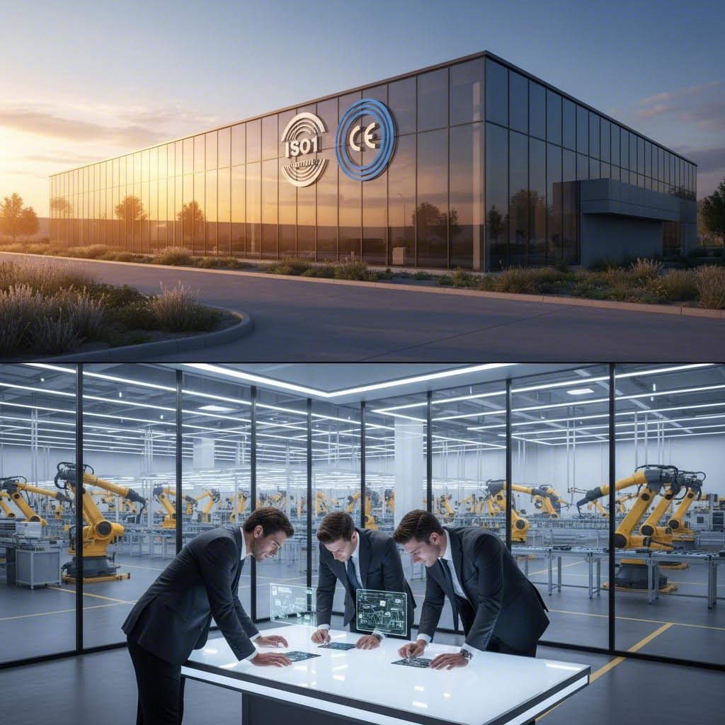
Rapid Sheet Metal Prototyping: From CAD File To Finished Part In Days
Understanding Rapid Sheet Metal Prototyping and Why It Matters
Imagine submitting your CAD file on Monday and holding a finished prototype sheet metal part by Friday. Sounds impossible? That's exactly what rapid sheet metal prototyping delivers—and it's transforming how engineers and product teams approach design validation.
At its core, rapid sheet metal prototyping refers to accelerated manufacturing processes that convert digital designs into functional metal parts within days rather than weeks. Unlike traditional metal fabrication methods that rely on extensive tooling, lengthy setup times, and sequential production workflows, this approach leverages modern laser cutting, CNC bending, and streamlined quality processes to compress timelines dramatically.
Traditional sheet metal fabrication typically requires 4-6 weeks from design submission to finished part delivery. Rapid prototyping compresses this timeline to just 3-7 days by eliminating tooling requirements and optimizing every stage of production.
What Sets Rapid Prototyping Apart from Standard Fabrication
Traditional manufacturing methods like CNC machining and die stamping are known for their material consistency and precision. However, they come with significant drawbacks for prototyping applications. These conventional approaches require extensive tooling investments and labor-intensive setup procedures, making them time-consuming and expensive for small production runs.
Sheet metal rapid prototyping eliminates these barriers through several key differences:
- No tooling required: Parts are cut and formed using programmable equipment that doesn't need custom dies
- Flexible design modifications: Changes can be implemented quickly without scrapping expensive tooling
- Production-grade materials: Prototypes use the same metals intended for final production, enabling real-world testing
- Scalable quantities: Whether you need one part or several hundred, the process adapts efficiently
Why Speed Defines Modern Product Development
Why does speed matter so much? In competitive markets, the ability to validate designs quickly creates measurable advantages. When you can test functional prototype sheet metal components in real-world conditions within days, your entire development cycle accelerates.
Consider the practical benefits. Faster design validation means your engineering team can identify issues early—before committing to production tooling that costs thousands of dollars. Reduced time-to-market helps you capture market opportunities ahead of competitors. And the ability to iterate quickly through multiple design versions leads to better final products.
According to HLH Prototypes, sheet metal prototyping delivers durable, production-grade parts that can be tested in real-life applications—something that alternative methods often can't match. This makes it particularly valuable for enclosures, weldments, and functional components where actual material properties matter.
Understanding these fundamentals positions you to make informed decisions about your prototyping strategy. The following sections will walk you through the complete workflow, material options, and technical specifications you'll need to leverage this approach effectively.
The Complete Rapid Prototyping Workflow Explained
So what actually happens after you submit your design file? Understanding each stage of the sheet metal prototype workflow helps you anticipate timelines and prepare materials that keep your project moving at full speed. Let's break down the journey from digital design to physical part.
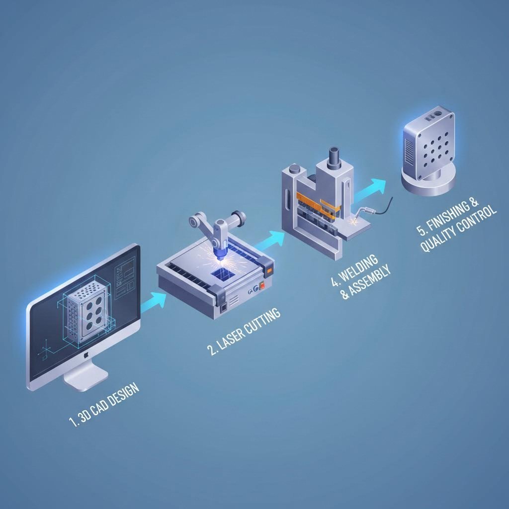
From CAD File to Physical Part in Five Stages
Every sheet metal processing project follows a predictable sequence. While the "rapid" label suggests speed, the efficiency comes from optimizing each stage rather than skipping critical steps. Here's how the complete workflow unfolds:
- Design File Preparation and Submission: The process begins when you submit your CAD files—typically in formats like STEP, IGES, or native SolidWorks files. Clear, production-ready drawings accelerate this stage significantly. According to Steampunk Fabrication, translating rough sketches or incomplete drawings into production-ready blueprints can stretch over several days if clarifications are needed. Submitting clean, dimensioned files with bend notes and material callouts can save 24-48 hours right from the start.
- Design for Manufacturability (DFM) Review: Engineers evaluate your design for potential fabrication challenges. They check bend radii, hole-to-edge distances, material formability, and tolerance stackups. This critical review identifies issues before metal cutting begins—catching problems that would otherwise cause delays or scrapped parts during production.
- Material Selection and Sourcing: Once the design passes DFM review, the appropriate material is selected or sourced. Fabricators typically stock common metals like aluminum, mild steel, and stainless steel. If your part uses one of these standard materials, production can begin immediately. However, specialty alloys or unusual thicknesses may require additional sourcing time.
- Cutting, Forming, and Assembly Operations: This is where metal cutting and bending services transform flat sheets into three-dimensional components. Laser cutting creates precise profiles, CNC press brakes form bends, and additional operations like welding or hardware insertion complete the fabrication. Modern equipment with stored programs can accelerate repeat orders considerably.
- Finishing and Quality Inspection: Parts often require surface treatments like powder coating, painting, or passivation. After finishing, quality inspections verify dimensions, examine welds, and check surface conditions against specifications. Industry sources note that thorough quality checks can add one to three days but ensure parts perform as expected once installed.
What Happens During DFM Review
The DFM analysis stage deserves special attention because it directly impacts both timeline and part quality. During this review, experienced engineers examine your design file for potential issues that could slow production or compromise the finished part.
What are they looking for? Common concerns include:
- Bend radii that are too tight for the specified material thickness
- Holes placed too close to bend lines or part edges
- Features that create tooling access problems
- Tolerance requirements that exceed standard capabilities
- Material specifications that affect formability or availability
Here's the key insight: a thorough DFM review upfront actually accelerates your timeline. Catching a design issue before parts fabrication begins prevents costly revision cycles. According to GTR Manufacturing, their collaborative approach involving multiple engineers at each step ensures prototypes meet the highest quality standards—reducing the risk of rework that would extend delivery dates.
When you receive DFM feedback, responding quickly keeps your project on track. Some manufacturers offer 24-hour quote turnarounds with DFM analysis included, giving you actionable feedback within a business day.
Factors That Accelerate or Delay Your Timeline
Understanding what speeds up or slows down each stage helps you plan more effectively. Here's what influences your sheet metal production timeline at each phase:
| Stage | Accelerators | Potential Delays |
|---|---|---|
| Design Submission | Clean CAD files, complete dimensions, material specs included | Incomplete drawings, missing tolerances, unclear bend notes |
| DFM Review | Designs following standard guidelines, quick response to feedback | Complex geometries, multiple revision cycles needed |
| Material Sourcing | Standard materials in stock (aluminum, mild steel, 304 stainless) | Exotic alloys, unusual thicknesses, supply chain shortages |
| Fabrication | In-house capabilities, simple geometries, stored programs | Complex sheet metal fabrication and assembly, outsourced operations |
| Finishing | Standard finishes, minimal post-processing | Custom coatings, extended curing times, specialty treatments |
For a straightforward prototype using standard materials and minimal finishing, you might receive parts in 5 to 7 business days. More complex orders involving custom assembly, specialty coatings, or large quantities could extend to 2 to 4 weeks. The difference often comes down to preparation—the more complete your initial submission, the smoother and faster the entire process flows.
With this workflow foundation in place, you're ready to explore the material options available for your project and understand how each choice affects both performance and timeline.
Material Selection Guide for Sheet Metal Prototypes
Choosing the right material for your prototype isn't just a checkbox exercise—it directly affects how your part performs under real-world conditions, how easily it forms during fabrication, and whether your prototype accurately represents final production intent. Get this decision wrong, and you might spend weeks testing a component that behaves nothing like the final product.
The good news? Most rapid prototyping applications rely on a handful of proven materials. Understanding their properties helps you match material characteristics to your functional requirements while keeping timelines fast and costs reasonable.
Aluminum vs Steel for Prototype Applications
When engineers approach material selection, the aluminum versus steel decision often comes first. Each material family offers distinct advantages depending on your application priorities.
Aluminum sheet metal delivers an unbeatable strength-to-weight ratio. If your application demands light components—think aerospace brackets, electronic enclosures, or portable equipment—aluminum alloys like 5052-H32 provide excellent formability with good corrosion resistance. According to Fictiv, certain aluminum grades offer great formability, making them suitable for complex designs and high-performance applications.
Steel options split into two main categories: mild steel and stainless steel sheet metal. Here's how they compare:
- 1018 Mild Steel: The workhorse material for structural applications. It's affordable, welds easily, and offers excellent formability. However, it requires protective coatings or paint to prevent rust. If your prototype will eventually be powder coated or painted in production, 1018 mild steel often makes the most practical choice.
- 304 Stainless Steel: The go-to grade when corrosion resistance matters. Medical devices, food processing equipment, and outdoor enclosures frequently specify 304 stainless for its durability in harsh environments. It costs more than mild steel but eliminates the need for protective coatings.
- 316 Stainless Steel Sheet Metal: When standard stainless isn't enough, 316 stainless steel offers superior resistance to chlorides and marine environments. Chemical processing equipment, pharmaceutical components, and coastal applications often require this premium grade.
The critical insight from industry sources? If your production material falls outside common prototyping options, substituting materials may mislead functional testing and compromise design validation. Whenever possible, prototype with the same material you'll use in production.
Material Thickness and Its Impact on Forming
Material thickness influences everything from bend radius capabilities to overall part rigidity. Understanding gauge specifications helps you communicate clearly with fabricators and anticipate forming limitations.
Sheet metal thickness is traditionally specified using gauge numbers, though most fabricators now work in decimal inches or millimeters. According to Harvard Steel Sales, standard manufacturer's gauge designations are no longer officially recognized in the domestic steel industry, which uses only decimals when referring to flat rolled product thickness. However, gauge numbers remain common reference points in daily transactions.
Here's what thickness means for your prototype:
- Thin gauges (24-28 gauge / 0.015"-0.024"): Ideal for electronics enclosures, decorative panels, and lightweight covers. These materials form easily but may require careful handling to avoid distortion.
- Medium gauges (16-20 gauge / 0.036"-0.060"): The sweet spot for most prototype applications. Brackets, housings, and structural components typically fall in this range, balancing formability with rigidity.
- Heavy gauges (10-14 gauge / 0.075"-0.135"): Structural applications requiring load-bearing capacity. These thicker materials need larger bend radii and may require more powerful forming equipment.
One important consideration: galvanized sheet metal uses slightly different gauge standards than uncoated steel. Per industry gauge charts, galvanized materials include the zinc coating in their thickness measurement, so a 16-gauge galvanized sheet (0.064") is thicker than a 16-gauge cold-rolled sheet (0.060").
Complete Material Comparison for Prototyping
The following table summarizes key characteristics across common prototyping materials, helping you match specifications to your project requirements:
| Material Type | Common Grades | Thickness Range | Best Applications | Relative Cost |
|---|---|---|---|---|
| Aluminum | 5052-H32, 6061-T6, 3003 | 0.020" - 0.190" | Lightweight enclosures, aerospace components, heat sinks | $$ |
| Mild Steel | 1008, 1010, 1018 | 0.015" - 0.239" | Structural brackets, machine guards, painted housings | $ |
| Stainless Steel (304) | 304, 304L | 0.018" - 0.190" | Food equipment, medical devices, corrosion-resistant enclosures | $$$ |
| Stainless Steel (316) | 316, 316L | 0.018" - 0.190" | Marine applications, chemical processing, pharmaceutical equipment | $$$$ |
| Galvanized Steel | G60, G90 coating weights | 0.016" - 0.168" | HVAC ductwork, outdoor enclosures, agricultural equipment | $-$$ |
| Copper | C110, C101 | 0.020" - 0.125" | Electrical components, thermal management, RF shielding | $$$$ |
| Brass | C260, C270 | 0.020" - 0.125" | Decorative hardware, electrical connectors, antimicrobial surfaces | $$$ |
Making Your Material Decision
So how do you choose? Start with your functional requirements. Ask yourself these questions:
- Does the part need to resist corrosion without coatings? Consider stainless steel.
- Is weight a primary concern? Aluminum sheet likely makes sense.
- Will the production part be painted or coated? Mild steel offers the best value.
- Does the application involve electrical conductivity? Copper or brass may be necessary.
- What environment will the finished product face? Marine or chemical exposure often requires 316 stainless steel.
Remember that material selection affects more than just part performance—it also influences your timeline. Standard materials like aluminum sheet, 304 stainless steel sheet, and 1018 mild steel typically ship from fabricator stock, keeping your project on the fast track. Specialty alloys or unusual thicknesses may require sourcing time that extends your delivery date.
With your material selected, the next critical decision involves understanding the manufacturing processes that will transform that flat sheet into your finished component.
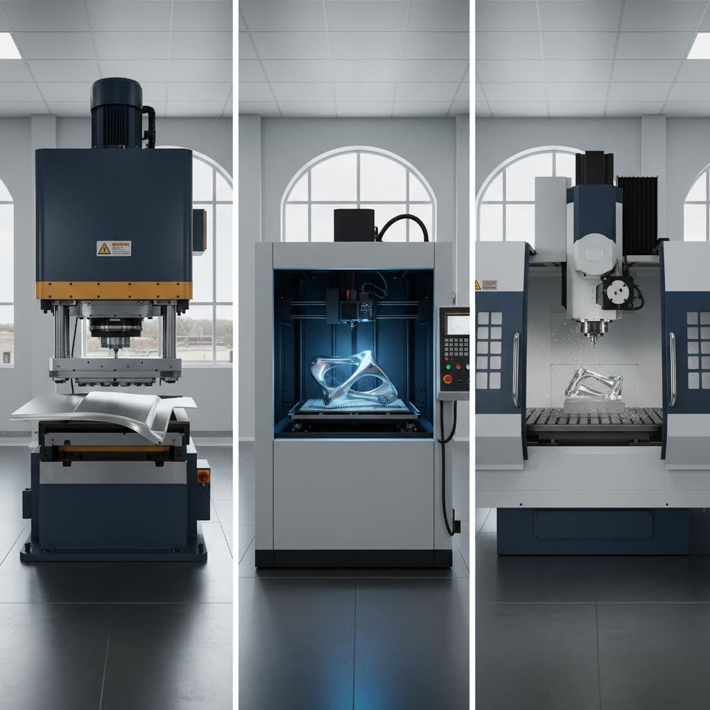
Core Manufacturing Processes and Technical Capabilities
You've selected your material and submitted a clean design file. Now what? The transformation from flat sheet to finished prototype relies on four primary manufacturing processes—each with distinct capabilities that affect your part's precision, appearance, and overall quality. Understanding these processes helps you design smarter and communicate more effectively with your fabrication partner.
Whether you're looking for metal bending near me or evaluating laser cutting options, knowing what each process can deliver ensures your expectations align with manufacturing reality.
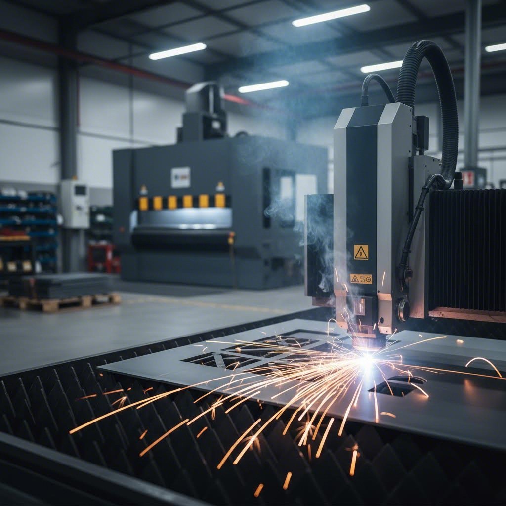
Laser Cutting Precision and Speed Advantages
The laser cutter has become the backbone of rapid sheet metal cutting operations. Why? It combines exceptional precision with remarkable speed—two factors that rarely coexist in manufacturing.
Modern fiber laser systems focus an intense beam of light to melt or vaporize material along programmed paths. This non-contact process eliminates tool wear concerns and enables intricate geometries that would be impossible with mechanical cutting methods. According to Stephens Gaskets, fiber lasers routinely achieve tolerances of ±0.05mm on metal sheets under 3mm thick—precision that rivals CNC machining at a fraction of the setup time.
Here's what makes laser cutting ideal for prototyping:
- No tooling required: Programs load directly from CAD files, eliminating custom die costs
- Rapid changeovers: Switching between part designs takes minutes, not hours
- Complex profiles: Intricate cutouts, small features, and tight radii cut cleanly
- Minimal material distortion: The focused heat zone reduces warping compared to plasma cutting
However, understanding kerf—the width of material removed by the cutting process—is essential for precision work. Laser kerf typically ranges from 0.1mm to 0.4mm depending on material type, thickness, and laser settings. Your fabricator compensates for kerf in programming, but extremely tight tolerances between mating parts should account for this factor.
What about tolerance variations across different materials? Industry specifications show that mild steel typically holds ±0.1 to ±0.25mm, stainless steel achieves ±0.1 to ±0.2mm, and aluminum runs slightly wider at ±0.15 to ±0.25mm due to its thermal properties. Thicker materials generally exhibit larger tolerance ranges because the heat-affected zone expands with material depth.
CNC Punching for High-Volume Features
When your prototype includes numerous identical features—mounting holes, ventilation patterns, or repetitive cutouts—CNC punching often proves more efficient than laser cutting. A metal cutter using punch technology stamps features using hardened tool sets at rates exceeding 300 hits per minute.
The trade-off? Punching requires tooling for each unique shape, making it less flexible for complex custom profiles. However, standard shapes like round holes, squares, and rectangles use common tool sets that fabricators keep in stock. For prototypes transitioning toward production, punching setups established during prototyping can scale seamlessly to higher volumes.
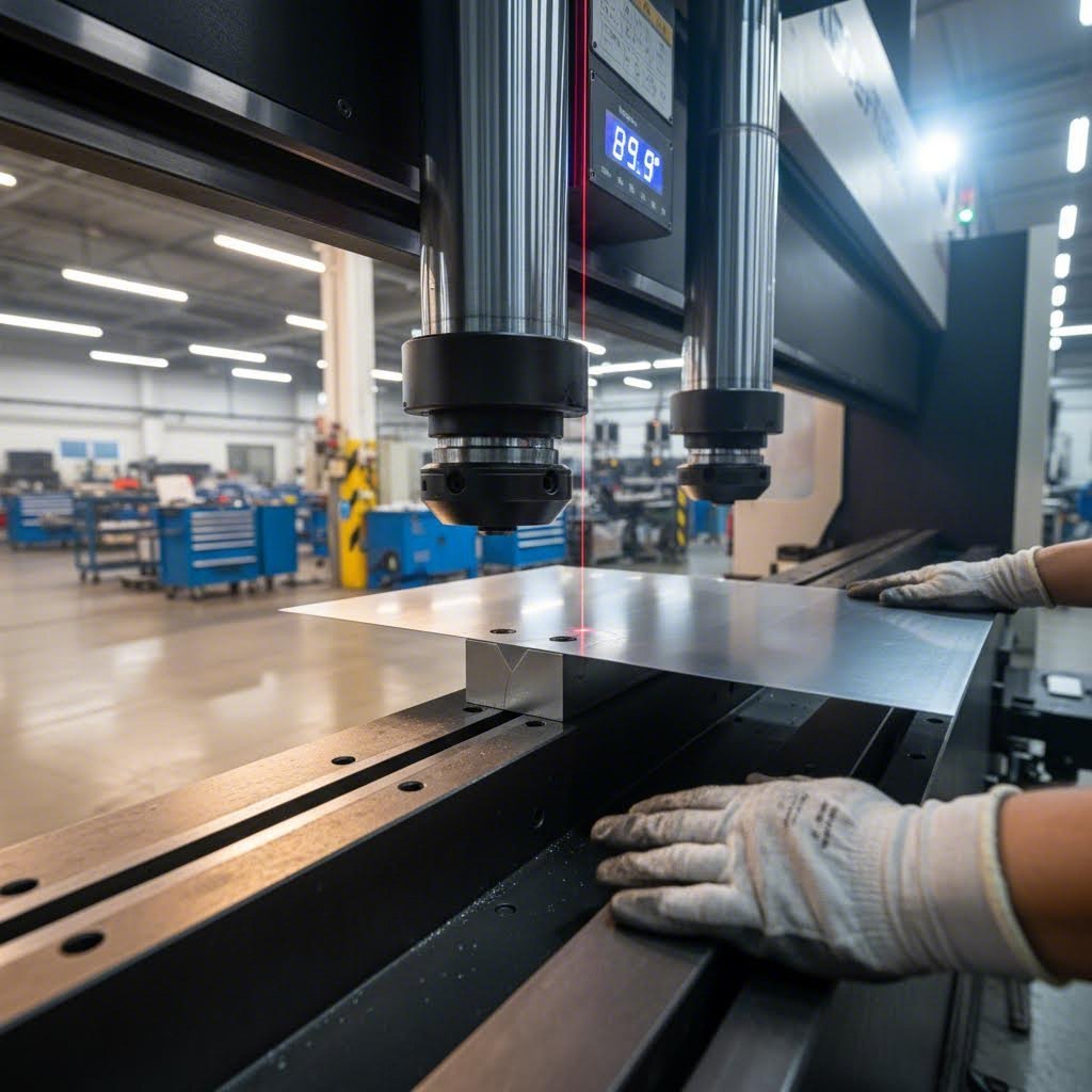
Bending Tolerances That Affect Part Fit
Sheet metal bending transforms flat laser-cut blanks into three-dimensional components. CNC press brakes apply precise force to form bends along programmed lines, but the physics of material deformation introduces tolerance considerations that designers must understand.
Here's the critical insight from Protolabs: tolerances stack across multiple bends. A single bend might hold ±0.25mm, but a part requiring four bends to position a mounting hole could accumulate ±0.76mm of positional variation plus angular tolerance of 1° per bend. This stacking effect explains why features spanning multiple bends need more generous tolerances than features on flat surfaces.
What can you do about it? Consider these strategies:
- Use floating hardware: Slots or oversized holes accommodate positional variation
- Keep critical features on common surfaces: Holes on the same flat face before bending maintain tighter relative positions
- Specify functional tolerances: Tell your fabricator which dimensions are critical versus which have flexibility
Bend radius also affects design decisions. The minimum inside bend radius depends on material type and thickness—typically equal to or greater than material thickness for aluminum, and 1.5x thickness for stainless steel. Attempting tighter radii risks cracking on the outside of the bend.
Aluminum Welding and Assembly Considerations
When your prototype requires joined components, welding becomes part of the process chain. Aluminum welding presents unique challenges compared to steel—it requires specialized TIG equipment, filler materials, and operator expertise. The material's high thermal conductivity disperses heat quickly, demanding precise technique to achieve sound welds without burn-through or distortion.
Steel welding offers more flexibility. MIG welding handles most mild steel and stainless steel prototypes efficiently, while TIG welding delivers cleaner aesthetics for visible joints. For production-intent prototypes, welding quality should match your final production specifications to validate both fit and structural integrity.
Process Capabilities Comparison
The following table summarizes key capabilities across primary manufacturing processes, helping you understand what each method delivers:
| Process | Typical Tolerance | Material Compatibility | Speed Characteristics | Best Applications |
|---|---|---|---|---|
| Fiber Laser Cutting | ±0.05 to ±0.25mm | Steel, stainless, aluminum, brass, copper | Very fast; complex profiles add minimal time | Intricate profiles, fine features, prototypes |
| CO₂ Laser Cutting | ±0.1 to ±0.4mm | Metals, plastics, rubber, wood | Moderate; wider kerf than fiber | Non-metallics, thicker materials |
| CNC Punching | ±0.1 to ±0.25mm | Steel, stainless, aluminum up to 6mm | Fastest for repetitive features | High hole counts, standard shapes |
| CNC Bending | ±0.25mm per bend; ±1° angular | All formable sheet metals | Fast setup; seconds per bend | All 3D formed components |
| TIG Welding | Dependent on joint design | All weldable metals including aluminum | Slower; precision-focused | Critical joints, aluminum, visible welds |
| MIG Welding | Dependent on joint design | Steel, stainless steel | Faster than TIG; production-oriented | Structural joints, steel assemblies |
Putting Process Knowledge to Work
Understanding these manufacturing capabilities empowers better design decisions. When you know that bending tolerances stack across multiple bends, you design with appropriate clearances. When you understand kerf and laser cutting tolerances, you can specify realistic dimensional requirements.
The best prototypes emerge when designers and fabricators collaborate with shared technical understanding. Armed with this process knowledge, you're ready to explore the design-for-manufacturability guidelines that translate into faster turnaround and fewer revision cycles.
Design for Manufacturability Guidelines That Save Time
You've learned about manufacturing processes and their tolerances. But here's the reality: even the most capable fabrication shop can't deliver rapid turnaround if your design creates unnecessary complications. The difference between a 5-day delivery and a 3-week ordeal often comes down to how well your CAD file follows design for manufacturability principles.
Sheet metal working presents unique challenges because the material bends, stretches, and responds to forming forces in ways that solid blocks don't. According to EABEL, many design errors happen because engineers rely too heavily on digital geometry without considering real forming limitations. Let's examine the most common mistakes and how to avoid them.
Five Design Mistakes That Delay Your Prototype
These errors account for the majority of revision cycles in sheet metal prototype fabrication. Catching them before submission saves days—sometimes weeks—on your project timeline.
1. Placing Holes Too Close to Bend Lines
When holes or slots sit near a bend, the forming process distorts them. The result? Oval holes, misaligned fasteners, and parts that don't fit their intended assemblies. According to HLH Rapid, holes should be positioned at least 2.5 times the material thickness (T) plus the bend radius (R) from any bend line. For slots, increase that distance to 4T + R.
2. Specifying Bend Radii That Are Too Tight
Requesting a very small inside radius increases cracking risk and causes excessive springback. Softer materials like aluminum tolerate smaller radii, but harder alloys typically need a minimum of 1x material thickness or greater. Your steel bending and fabrication partner may need to use special tooling—or reject the design entirely—if radii specifications don't match material capabilities.
3. Missing or Incorrect Bend Relief
When two bends intersect without proper relief cuts, the sheet tears or buckles at corners. Relief cuts are small notches that allow material to fold cleanly without interference. As industry experts note, adding appropriate bend relief—whether rectangular, obround, or circular—lets material fold properly and reduces tooling stress.
4. Ignoring Grain Direction
Sheet metal has a grain direction from the rolling process. Bending perpendicular to the grain reduces crack risk, while bending parallel to it on tight radii invites failure. Design references emphasize checking grain direction and hole orientation in the flat pattern before finalizing drawings—especially for parts with sharp radii.
5. Designing Flanges Shorter Than Minimum Length
Short flanges can't be properly clamped during forming, leading to slipping and inconsistent bends. The general guideline requires flange length of at least 4 times the material thickness. If your design demands a shorter edge, discuss alternative bend sequences or geometry modifications with your fabricator.
Optimizing Your Design for Faster Turnaround
Avoiding mistakes is half the equation. Proactive optimization accelerates your sheet metal design services engagement and reduces revision cycles. Here's how to prepare designs that move through fabrication at maximum speed.
- DO: Keep inside bend radii consistent throughout your part. Varying radii forces tool changes and extends production time.
- DON'T: Specify non-standard hole sizes unless functionally necessary. Odd dimensions require laser cutting instead of faster punch operations.
- DO: Maintain minimum hole-to-edge distances of at least 2x material thickness. Holes too close to edges cause bulging during punching.
- DON'T: Request tight tolerances on formed features unless absolutely required. According to manufacturing experts, treating sheet metal like machined parts drives up cost—forming has natural variation that should be accommodated.
- DO: Use rounded transitions at external corners. Sharp corners create safety hazards and accelerate die wear, as noted by RP World. Minimum corner radius should be at least 0.5T or 0.8mm, whichever is greater.
- DON'T: Create long cantilevers or narrow slots with widths less than 1.5 times material thickness. These features weaken punch tooling and shorten die life.
- DO: Plan for downstream processes during design. If your part requires welding, account for heat distortion. If it needs coating, remember that paint adds thickness affecting fits.
- DON'T: Overlook flat pattern verification. Complex structures may have insufficient clearance or material interference when unfolded—catch this in CAD before submission.
The Connection Between DFM and Speed
Why does all this matter for rapid prototyping? Every design issue that requires clarification adds hours or days to your timeline. When you're seeking sheet metal bending near me for quick turnaround, a design that sails through DFM review without questions moves directly into production.
Consider this workflow impact: a well-prepared design might receive instant quote approval and begin cutting the same day. A design with multiple issues could require two or three email exchanges over several days before fabrication even starts. The "rapid" in rapid sheet metal prototyping depends heavily on your preparation.
Custom sheet metal fab operations work fastest when designs follow predictable patterns. Use standard materials, consistent bend radii, proper clearances, and reasonable tolerances. Collaborate early with your fabrication partner if your design pushes boundaries—they can often suggest modifications that maintain functionality while improving manufacturability.
With these sheet metal engineering principles guiding your designs, you're positioned to receive prototypes faster and with fewer surprises. The next consideration? Understanding how this approach compares to alternative prototyping methods like 3D printing and CNC machining.
Rapid Sheet Metal vs Alternative Prototyping Methods
So you need a functional metal prototype—but which manufacturing method actually makes sense for your project? The answer isn't always obvious. Prototyping sheet metal competes directly with 3D printing and CNC machining, and each approach excels in different scenarios. Choosing wrong means wasted time, inflated budgets, or prototypes that don't accurately represent your production intent.
Let's break down when each method delivers the best results, so you can make informed decisions that accelerate your development cycle rather than derailing it.
When Sheet Metal Beats 3D Printing for Prototypes
Metal 3D printing has captured significant attention for its design freedom—but that flexibility comes with trade-offs that matter for functional testing. According to Met3DP's 2025 analysis, 3D printed parts can reduce weight by 30% compared to sheet metal equivalents through topology optimization. Sounds compelling, right?
Here's the catch: rapid prototyping sheet metal delivers production-grade material properties that 3D printing often can't match. When your prototype needs to survive real-world stress testing, thermal cycling, or regulatory certification, the material behaves exactly like your future production parts. A 3D printed prototype might look identical but respond completely differently under load.
Consider these scenarios where prototype sheet metal fabrication outperforms additive alternatives:
- Functional enclosures requiring EMI shielding: Sheet metal's continuous conductive surface provides reliable electromagnetic protection that 3D printed structures struggle to replicate
- Parts undergoing production-intent stress testing: Formed sheet metal exhibits the same fatigue characteristics as your eventual production components
- Projects with tight budgets at low volumes: Metal 3D printing typically costs $100-$500 per part versus $50-$200 for comparable sheet metal components
- Prototypes requiring post-processing like welding or threading: Standard metal alloys accept secondary operations without the anisotropy concerns of additive materials
That said, 3D printing wins decisively for complex internal geometries, consolidated assemblies, or organic shapes that would be impossible to form from flat sheets. The key insight from Protolabs? Many engineers use 3D printing for early concept models, then transition to sheet metal for functional validation—capturing the benefits of both approaches at appropriate development stages.
Choosing Between CNC Machining and Formed Sheet Metal
CNC machining offers exceptional precision and material uniformity. When your metal prototype demands tight tolerances on every feature, machining from solid stock often seems like the obvious choice. But this approach has hidden costs that affect both timeline and budget.
Machining removes material from solid blocks—typically 60-80% of the starting material becomes chips. For enclosures, brackets, and structural components, this subtractive approach proves dramatically less efficient than forming flat sheets. A sheet metal bracket might use 95% of its starting material, while a machined equivalent wastes the majority.
More importantly for rapid metal prototyping, machining setups take longer. Complex multi-sided parts require multiple fixturing operations, each adding time. Sheet metal components often complete fabrication in a single cutting and bending sequence.
When does CNC machining still make sense?
- Solid, prismatic parts: Blocks, manifolds, and thick-walled components that can't be formed from sheet
- Extremely tight tolerances: When features require ±0.025mm or better across the entire part
- Complex 3D surfaces: Sculptural shapes or compound curves that sheet forming can't achieve
- Very small quantities of unique parts: Single prototypes where sheet metal setup costs don't amortize
For most metal prototyping applications involving enclosures, chassis, brackets, and formed components, sheet metal delivers faster turnaround at lower cost while producing parts that transition smoothly to volume production.
Comparative Decision Framework
The following table summarizes key differences across all three metal prototype methods, helping you match manufacturing approach to project requirements:
| Criteria | Rapid Sheet Metal | Metal 3D Printing | CNC Machining |
|---|---|---|---|
| Material Options | Aluminum, steel, stainless, copper, brass in various gauges | Titanium, Inconel, aluminum, stainless, tool steels | Nearly any machinable metal including exotics |
| Typical Lead Time | 3-7 days for simple parts; 2-3 weeks for complex assemblies | 1-3 weeks depending on build size and post-processing | 3-10 days for most parts; longer for complex setups |
| Cost at Low Volumes (1-10 parts) | $50-$200 per part typical | $100-$500+ per part | $75-$400 per part depending on complexity |
| Geometric Limitations | Limited to formable shapes; minimum bend radii apply; no internal cavities | Excellent for complex internal structures; some overhangs need supports | Requires tool access; internal features limited by reach |
| Production Transition Path | Direct—same processes scale to production volumes seamlessly | Often requires redesign for injection molding or machining at volume | Scales well but costs don't decrease dramatically with volume |
Making Your Method Selection
Here's the practical decision path: Start by asking what you're trying to learn from your prototype. If you need functional validation with production-representative materials and a clear path to manufacturing scale, rapid sheet metal prototyping typically wins. If you're exploring radical geometries or need consolidated assemblies, 3D printing opens possibilities sheet metal can't match. If precision on solid features trumps everything else, CNC machining remains the gold standard.
Many successful prototype services combine methods strategically. You might 3D print early concepts for stakeholder review, then produce sheet metal prototypes for engineering validation and regulatory testing. The goal isn't finding one universal solution—it's matching the right method to each development phase.
With your manufacturing method selected, the next step involves understanding how these approaches apply to specific industry requirements, from automotive chassis components to medical device enclosures.
Industry Applications from Automotive to Medical Devices
Understanding manufacturing processes and material options is essential—but how do these translate to your specific industry? The requirements for an automotive chassis bracket differ dramatically from those of a medical device enclosure. Each sector brings unique certification demands, material specifications, and testing protocols that shape how sheet metal prototypes must be designed and validated.
Let's explore what rapid prototyping looks like across four major industries, giving you the practical guidance needed to align your prototype strategy with sector-specific expectations.
Automotive Chassis and Structural Component Prototyping
Automotive applications represent one of the most demanding environments for sheet metal products. Chassis components, suspension brackets, and structural reinforcements must survive extreme stress cycles while meeting increasingly stringent lightweighting targets.
According to Jeelix's 2025 automotive fabrication analysis, the industry has shifted dramatically from traditional stamping-and-welding workflows toward digitally validated, multi-stage forming processes. This evolution directly impacts how prototypes are developed and tested.
Key considerations for automotive sheet metal prototypes include:
- Material selection complexity: Advanced High-Strength Steels (AHSS) and third-generation alloys now dominate structural applications. These materials offer tensile strengths between 600-1500 MPa but present "springback" challenges that require careful simulation before physical prototyping.
- IATF 16949 certification requirements: Production suppliers must maintain this automotive-specific quality management certification. When prototyping, working with IATF-certified partners ensures your validation parts come from processes that will scale to production.
- Crash safety validation: Custom metal parts for structural applications often require destructive testing. Your prototype quantity planning should account for parts consumed during impact and fatigue testing protocols.
- Tolerance stacking across assemblies: Body-in-White engineering demands careful tolerance allocation. According to industry sources, leading manufacturers like Daimler use flexible body tolerance simulation rather than rigid-body assumptions—a consideration that should influence your prototype dimensioning.
- Hybrid joining methods: Modern automotive structures combine laser welding, self-piercing rivets, and structural adhesives. Your prototype should validate these joining approaches rather than substituting simpler methods.
The path from prototype to production in automotive typically involves rigorous supplier qualification. Metal parts fabrication partners who understand this journey can help you design prototypes that generate meaningful validation data while positioning you for seamless production transition.
Aerospace Component Requirements
Aerospace applications push material and process capabilities to their limits. While sharing some characteristics with automotive, aerospace sheet metal fabrication demands even tighter controls and more extensive documentation.
- Material traceability: Every sheet metal blank must trace back to certified mill sources. Heat lot numbers, material certifications, and processing records follow each part through fabrication.
- AS9100 certification: This aerospace-specific quality standard goes beyond ISO 9001, adding requirements for configuration management, risk assessment, and operational controls that affect prototype production.
- Aluminum alloy specifications: Aerospace commonly uses 2024-T3 and 7075-T6 aluminum rather than the 5052 and 6061 grades typical in commercial applications. These higher-strength alloys have different formability characteristics that affect bend radii and tooling requirements.
- Surface treatment protocols: Anodizing, chemical conversion coatings, and specialized primers follow aerospace specifications like MIL-DTL-5541 or MIL-PRF-23377. Prototype finishes should match production intent.
- First Article Inspection (FAI): Formal AS9102 documentation may be required even for prototype quantities, validating that your fabrication process produces parts meeting all drawing requirements.
Electronics Enclosure Prototyping
Electronics enclosures present a unique combination of aesthetic, functional, and regulatory requirements. Sheet metal enclosure design services must balance EMI shielding effectiveness, thermal management, and cosmetic appearance.
- EMI/RFI shielding requirements: Continuous conductive surfaces with proper grounding and gasketing protect sensitive electronics. Prototype enclosures should include actual shielding features rather than simplified geometries.
- Thermal management integration: Ventilation patterns, heat sink mounting provisions, and fan cutouts affect both form and function. Your prototype quantity should include units for thermal testing under operational loads.
- IP ratings for environmental protection: If your product requires IP67 or IP68 protection, prototype enclosures need proper sealing features to validate ingress protection during testing.
- UL and CE compliance considerations: Safety certifications often require specific material grades, wall thicknesses, and grounding provisions. Design these into your prototype from the start.
- Cosmetic finish requirements: Consumer-facing products demand consistent powder coating, painting, or brushed finishes. Prototype finishing should represent production appearance accurately.
Medical Device Enclosure Requirements
Medical device applications carry perhaps the highest stakes—and the most rigorous regulatory oversight. According to Pinnacle Precision, precision sheet metal fabrication plays a crucial role in producing highly reliable and safe medical devices, from diagnostic equipment to surgical tools and electronic enclosures.
What makes medical sheet metal prototypes unique?
- Biocompatibility requirements: Components contacting patients or sterile environments must use compatible materials. Stainless steel (304 and 316 grades) and titanium dominate medical applications for their proven biocompatibility profiles.
- Corrosion resistance for sterilization: Medical devices undergo repeated sterilization cycles—autoclaving, chemical sterilization, or gamma irradiation. Industry experts emphasize choosing materials and finishes that resist corrosion through these harsh processes.
- ISO 13485 certification: This medical-specific quality management standard governs design and manufacturing processes. Working with ISO 13485-certified fabricators provides documented quality systems that regulatory submissions may require.
- FDA compliance documentation: Device History Records (DHR) and Design History Files (DHF) require extensive manufacturing documentation. Your prototype fabrication partner should understand these documentation requirements.
- Zero-tolerance quality control: As medical fabrication specialists note, medical components require precision manufacturing with zero tolerance for defects. Multi-stage inspections, CMM verification, and complete material traceability are standard expectations.
- Surface finish specifications: Electropolishing and passivation treatments create smooth, cleanable surfaces essential for hygienic applications. Specify these finishes on your prototype to validate appearance and cleanability.
Matching Your Industry to the Right Partner
Each industry vertical demands specialized expertise. A fabricator excelling at automotive metal fabrication parts may lack medical device experience—and vice versa. When evaluating potential partners, verify their certifications align with your sector requirements and ask for relevant project references.
The most effective prototype programs select partners who understand not just how to make your part, but why specific features matter for your application. This industry knowledge translates into better DFM feedback, appropriate material recommendations, and testing protocols that generate meaningful validation data.
With industry-specific requirements understood, the next critical question becomes: what will this actually cost, and how can you budget effectively for your prototype project?
Cost Factors and Budgeting for Your Prototype Project
You've selected your material, optimized your design, and identified the right manufacturing processes. Now comes the question every project manager and engineer asks: what's this actually going to cost? Understanding sheet metal manufacturing pricing helps you budget accurately and avoid unwelcome surprises when quotes arrive.
Here's the challenge—prototype costs vary dramatically based on multiple interacting factors. A simple bracket might cost $50, while a complex enclosure with tight tolerances and specialty finishes could run $500 or more. The difference comes down to understanding what drives those numbers.
Key Cost Drivers in Sheet Metal Prototyping
According to TZR Metal's cost analysis, increased complexity equals increased cost across nearly every variable. But not all factors carry equal weight. Here are the primary cost drivers ranked by typical impact on your custom cut sheet metal project:
- Material type and grade: Raw material often represents the largest single cost component. Carbon steel is generally least expensive, followed by aluminum, then stainless steel grades. Specialty materials like copper, brass, or titanium command premium pricing. As industry sources note, material prices fluctuate based on global market dynamics, so quotes may vary over time.
- Part complexity and tolerance requirements: Intricate geometries, numerous bends, tight tolerances, and complex cutouts require more programming time, longer machine cycles, and increased inspection efforts. Tolerances tighter than standard practice significantly increase manufacturing difficulty and scrap potential.
- Quantity ordered: Setup costs—programming, tooling configuration, first-article inspection—are amortized over your production run. Larger quantities spread these fixed costs thinly, dramatically reducing per-part pricing compared to single prototypes.
- Finishing requirements: Surface treatments add both material and labor costs. Basic powder coating might add $2-5 per square foot of surface area, while specialized plating or multi-layer finishes can reach $5-15+ per square foot according to metal sheet fabrication cost data.
- Assembly complexity: If your project involves plate fabrication with multiple components requiring welding, hardware insertion, or sub-assembly, labor costs accumulate. Shop rates for assembly work typically range from $50-100+ per hour.
- Turnaround time: Standard lead times allow fabricators to schedule production optimally. Expedited requests almost always incur premium charges for overtime, rushed material sourcing, and disrupted scheduling.
How Turnaround Time Affects Your Quote
The "rapid" in rapid prototyping doesn't come free. When you need custom cut metal parts faster than standard lead times allow, expect pricing adjustments that reflect the operational disruption your urgency creates.
Standard turnaround—typically 7-10 business days for straightforward parts—lets fabricators batch similar jobs, optimize material usage through efficient nesting, and schedule labor predictably. Rush orders break this efficiency.
What does expediting actually cost? While specific premiums vary by fabricator, expect 25-50% upcharges for moderately accelerated timelines and 50-100%+ for same-week or next-day requirements. According to CAD Crowd's prototyping cost analysis, time constraints often mean hastening the process through rushed shipping and additional man-hours—expenses that pass directly to you.
Many fabricators now offer laser cutting instant quote tools and custom metal fabrication online platforms that show exactly how turnaround time affects pricing. Use these tools to find the sweet spot between speed and budget for your specific project.
Optimizing Designs for Cost Efficiency
Smart design decisions reduce costs without sacrificing functionality. According to Protolabs' cost reduction guide, several strategies consistently deliver savings:
- Simplify geometry: Question every complex curve, tight tolerance, and specialized feature. Can you achieve the same function with simpler forms?
- Standardize features: Use common hole sizes, consistent bend radii, and readily available hardware. Non-standard specifications require special tooling or slower processes.
- Optimize material utilization: Consider whether slight dimension adjustments could fit parts more efficiently onto standard sheet sizes, reducing scrap.
- Avoid over-specification: If mild steel meets your functional requirements, don't specify stainless. If standard tolerances work, don't request precision that drives up inspection costs.
- Delay cosmetic finishes: During early prototyping stages, basic finishes may suffice. Reserve expensive treatments like silkscreening or engraving for later iterations when appearance matters.
- Include complete documentation: According to industry experts, providing hardware BOMs and clear specifications prevents email exchanges that slow quoting and add administrative overhead.
The most impactful cost optimization? Engage your fabricator during design. Their Design for Manufacturability expertise can identify cost drivers and suggest modifications before designs are finalized—preventing expensive redesigns and production complications that far exceed any upfront consultation costs.
With cost factors understood and optimization strategies in hand, you're ready to evaluate potential manufacturing partners and plan your path from prototype to production.
Selecting the Right Partner for Your Prototyping Needs
You've optimized your design, selected materials, and budgeted your project. Now comes perhaps the most consequential decision: choosing the manufacturing partner who will transform your CAD file into functional prototype sheet metal parts. This choice affects everything—timeline reliability, part quality, communication experience, and your eventual path to production.
Whether you're searching for metal fabricators near me or evaluating global suppliers, the evaluation process follows consistent principles. Let's walk through the criteria that separate exceptional partners from those who might derail your project.
Evaluating Manufacturer Capabilities and Certifications
Certifications tell you more than a fabricator's marketing claims ever could. They represent third-party verification that a company follows documented quality systems consistently. According to RapidDirect's industry analysis, ISO 9001 serves as the baseline quality standard—but specific industries demand more.
Here's what certifications signal about partner capabilities:
- ISO 9001: Fundamental quality management systems are in place. This is table stakes for any serious sheet metal fabrication shop.
- IATF 16949: Automotive-specific quality requirements including production part approval processes, failure mode analysis, and supplier development. Essential for chassis, suspension, and structural component prototyping.
- AS9100: Aerospace quality management covering configuration control, risk management, and traceability requirements beyond standard ISO.
- ISO 13485: Medical device quality systems including design controls and regulatory compliance documentation.
Beyond certifications, evaluate in-house capabilities carefully. According to TMCO's fabrication partner guide, fabrication shops near me that outsource critical operations—machining, finishing, or assembly—introduce communication gaps, quality inconsistencies, and timeline delays. Full-service facilities maintain tighter control over every production stage.
What capabilities should you verify?
- Laser cutting, CNC punching, or waterjet cutting for your material types
- CNC press brake bending with appropriate tonnage for your thicknesses
- Welding capabilities matching your material requirements (TIG for aluminum, MIG for steel)
- Finishing options including powder coating, painting, plating, or passivation
- Inspection equipment like CMMs for dimensional verification
- Assembly and hardware insertion if your project requires it
The Critical Role of DFM Support
Quick turn sheet metal fabrication depends heavily on catching design issues before production begins. According to industry experts, successful fabrication doesn't begin at the machine—it begins with engineering. The best sheet metal fabricators collaborate with you early, reviewing drawings, CAD files, tolerances, and functional requirements.
When evaluating DFM support capabilities, ask these questions:
- Do they provide automated DFM feedback through their quoting platform?
- Can their engineers discuss design modifications to improve manufacturability?
- How quickly do they respond to technical questions during the quoting process?
- Do they offer material and design recommendations based on your application?
For example, Shaoyi (Ningbo) Metal Technology demonstrates the level of DFM support you should expect from qualified partners. Their comprehensive DFM analysis pairs with 12-hour quote turnaround, giving you actionable feedback within a single business day. This rapid response capability—combined with their 5-day rapid prototyping to production timeline—exemplifies what aluminum sheet metal fabrication partners should deliver for time-sensitive projects.
Communication and Responsiveness
Technical capability means nothing if you can't reach anyone when questions arise. According to fabrication industry guidance, transparent communication is equally critical as technical expertise. A reliable fabricator provides clear timelines, project updates, and realistic expectations throughout the engagement.
Evaluate responsiveness during the quoting phase—it predicts behavior during production. If emails take days to answer before you've placed an order, expect similar delays when you need production updates or design clarifications.
Consider these communication indicators:
- Quote turnaround time: Leading prototype sheet metal parts suppliers deliver quotes within 12-24 hours for standard requests
- Technical accessibility: Can you speak directly with engineers, or only sales representatives?
- Project visibility: Do they provide production status updates proactively?
- Issue escalation: How quickly do they address problems when they arise?
Planning Your Path from Prototype to Production
Your prototype project exists within a larger product development context. According to Fictiv's production transition guide, the journey from initial prototype to mass production is a complex transformation—and working with an experienced manufacturing partner from the outset offers a streamlined path that mitigates risk down the road.
When evaluating custom sheet metal fabrication near me options, consider scalability from day one:
- Process consistency: Will your production parts use the same processes as your prototypes? Partners like Shaoyi offer seamless transition from 5-day rapid prototyping to automated mass production using consistent IATF 16949-certified quality systems.
- Volume capacity: Can they scale from 10 prototypes to 10,000 production parts without changing suppliers?
- Design for Assembly feedback: According to manufacturing experts, understanding DFA helps reduce issues when transitioning from manually assembling prototypes to automated production lines.
- Supply chain stability: Established partners maintain material relationships and production capacity that newer operations may lack.
The ideal partner understands not just how to fabricate your current prototype, but how that prototype fits into your larger production goals. For automotive applications specifically, this means working with manufacturers who understand chassis, suspension, and structural component requirements—and hold the IATF 16949 certification that production programs will require.
Partner Evaluation Checklist
Use this framework when comparing potential sheet metal fabricators:
| Evaluation Criteria | Questions to Ask | Red Flags |
|---|---|---|
| Certifications | Which quality certifications do you hold? Are they current? | Expired certifications, no third-party audits |
| In-House Capabilities | What operations do you outsource? What equipment do you own? | Critical processes outsourced, limited equipment range |
| DFM Support | How do you provide manufacturability feedback? What's your quote turnaround? | No engineering review, quotes taking 5+ days |
| Communication | Who is my point of contact? How do you provide project updates? | Sales-only contact, no proactive updates |
| Industry Experience | Have you worked with companies in my industry? Can you share references? | No relevant experience, unwilling to provide references |
| Scalability | Can you transition my project from prototype to production volumes? | Prototype-only capabilities, no volume capacity |
Making Your Final Selection
The right manufacturing partner accelerates your entire product development cycle. They catch design issues early through thorough DFM review, deliver prototypes on promised timelines, and provide the quality documentation your industry requires.
For teams developing automotive components, partners like Shaoyi (Ningbo) Metal Technology demonstrate the complete capability profile: IATF 16949 certification for automotive quality requirements, 5-day rapid prototyping capability for fast design iteration, comprehensive DFM support to optimize manufacturability, and automated mass production capacity for seamless scaling. Their 12-hour quote turnaround exemplifies the responsiveness that keeps aggressive development schedules on track.
Whatever your industry, invest time in partner evaluation proportional to project importance. A few extra days spent qualifying the right fabrication partner prevents weeks of delays, revision cycles, and quality issues that derail product launches. The goal isn't finding the cheapest quote—it's finding the partner whose capabilities, communication, and quality systems align with your project requirements and production ambitions.
Frequently Asked Questions About Rapid Sheet Metal Prototyping
1. How long does rapid sheet metal prototyping typically take?
Rapid sheet metal prototyping typically delivers finished parts in 3-7 business days for straightforward designs using standard materials. More complex projects involving specialty alloys, custom finishing, or assembly requirements may extend to 2-4 weeks. Factors that accelerate timelines include submitting clean CAD files with complete dimensions, using stock materials like aluminum or 304 stainless steel, and responding quickly to DFM feedback. Partners like Shaoyi offer 5-day rapid prototyping with 12-hour quote turnaround to keep aggressive schedules on track.
2. How much does custom sheet metal fabrication cost?
Custom sheet metal fabrication costs range from $50-$500+ per part depending on several factors. Material type significantly impacts pricing, with mild steel being most economical, followed by aluminum, then stainless steel grades. Part complexity, tolerance requirements, quantity ordered, finishing requirements, and turnaround time all influence final pricing. Rush orders typically add 25-100% premiums. To optimize costs, use standard materials, simplify geometry where possible, specify only necessary tolerances, and provide complete documentation to minimize revision cycles.
3. What materials are commonly used in sheet metal prototyping?
The most common materials for sheet metal prototyping include aluminum alloys (5052-H32, 6061-T6) for lightweight applications, mild steel (1008, 1010, 1018) for structural components requiring coating, 304 stainless steel for corrosion resistance, and 316 stainless steel for marine or chemical environments. Galvanized steel suits outdoor applications, while copper and brass serve electrical and thermal management needs. Material selection should match your production intent since prototyping with different materials can compromise functional validation results.
4. What is the difference between sheet metal prototyping and 3D printing?
Sheet metal prototyping uses production-grade materials with identical properties to final manufactured parts, making it ideal for functional stress testing and regulatory certification. 3D printing offers greater geometric freedom for complex internal structures but often requires redesign for volume production. Sheet metal typically costs $50-$200 per part versus $100-$500+ for metal 3D printing. Sheet metal also provides direct production scalability since the same processes work at any volume, while 3D printed parts often need complete manufacturing method changes for mass production.
5. How do I find reliable sheet metal fabrication services near me?
When searching for sheet metal fabricators, prioritize partners with relevant certifications (ISO 9001 minimum, IATF 16949 for automotive, AS9100 for aerospace, ISO 13485 for medical). Evaluate in-house capabilities to ensure they can handle cutting, bending, welding, and finishing without outsourcing. Assess DFM support quality and quote turnaround times, with leading fabricators delivering quotes within 12-24 hours. Request references from similar projects and verify their ability to scale from prototype quantities to production volumes seamlessly.