 Small batches, high standards. Our rapid prototyping service makes validation faster and easier —

Progressive Die Metal Stamping Secrets Your Tooling Engineer Won't Tell You
What Is Progressive Die Metal Stamping and Why It Dominates High-Volume Production
Ever wondered how manufacturers produce millions of identical metal parts with jaw-dropping precision and speed? The answer lies in a process that transforms raw sheet metal into complex components through a carefully orchestrated journey. Progressive die metal stamping stands as the backbone of high-volume manufacturing, yet many engineers and buyers only scratch the surface of what makes this process so powerful.
Progressive die metal stamping is a metal forming process where sheet metal advances through multiple stations within a single die, with each station performing a specific operation—such as cutting, bending, or forming—until the finished part emerges at the final station.
How Progressive Die Stamping Transforms Raw Metal into Precision Parts
So what is dies in manufacturing? In the context of progressive tooling, a die is the specialized tool that shapes metal through applied force. Think of it as a precisely engineered mold that contains all the stations needed to transform a flat metal strip into a finished component. Unlike single-operation stamping where one press stroke performs just one task, progressive die and stamping combines multiple operations into a continuous, automated workflow.
Here's why this matters: traditional stamping methods require moving parts between separate machines for each operation. This means more handling, more setup time, and more opportunities for error. Progressive stamping eliminates these inefficiencies by keeping the workpiece connected to a carrier strip that advances through the die with each press stroke. The result? According to Aranda Tooling, manufacturers can produce up to half a million parts daily using this method.
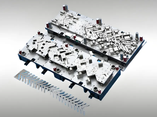
The Station-by-Station Journey of Sheet Metal
Imagine a coil of sheet metal entering a stamping die. With each press cycle, the material advances forward, and something remarkable happens at every stop along the way. One station might punch pilot holes for alignment. The next might cut the basic shape. Another bends flanges or adds embossed features. By the time the metal reaches the final station, it's no longer a flat strip—it's a precision-engineered component ready for assembly.
This station-by-station approach delivers advantages that single-operation methods simply cannot match:
- Faster production speeds through continuous feeding
- Lower per-part costs due to reduced labor and handling
- Tighter tolerances from consistent, repeatable operations
- Minimal scrap through optimized stamping die design
For engineers specifying components, buyers sourcing suppliers, and manufacturing decision-makers evaluating production methods, understanding progressive stamping isn't optional—it's essential. This process dominates industries from automotive to electronics precisely because it delivers the trifecta manufacturers demand: speed, precision, and cost efficiency at scale.
Inside the Die Stations That Shape Every Progressive Stamped Part
Now that you understand how sheet metal travels through a progressive die, let's pull back the curtain on what actually happens at each stop along the way. This is where the real engineering magic occurs—and where most general overviews fall short. Each station in a sheet metal die performs a specific task, and understanding these functions gives you the knowledge to evaluate designs, troubleshoot issues, and communicate effectively with your tooling partners.
Blanking and Piercing Stations Where Precision Begins
The progressive die stamping process typically starts with operations that remove material—think of these as the "cutting" stages of the journey. But don't let the simplicity fool you. The precision required here sets the foundation for everything that follows.
Blanking stations cut the initial outline shape from the metal strip. Picture a cookie cutter punching through dough, except with tolerances measured in thousandths of an inch. The punch descends into the die opening, shearing the metal cleanly along the desired profile. This operation often occurs toward the end of the die progression, but the shape it creates determines the part's final dimensions.
Piercing stations create holes, slots, and internal cutouts. These typically appear early in the die sequence for a critical reason: pilot holes. You'll notice small holes punched in the first stations that don't appear on the finished part. These pilot holes engage with pins in subsequent stations to ensure perfect alignment as the strip advances. Without this precision indexing, cumulative positioning errors would make tight tolerances impossible.
Here's something your tooling engineer might not emphasize: the clearance between punch and die opening dramatically affects edge quality. Too tight, and you'll see excessive tool wear. Too loose, and burrs become a persistent headache. For most sheet metal pressings, clearances typically range from 5% to 10% of material thickness per side.
Forming, Bending, and Coining Operations Explained
Once holes are pierced and features are positioned, the progressive dies begin reshaping the flat metal into three-dimensional geometry. These forming operations require careful sequencing—you can't bend a flange before cutting the relief that allows it to form without tearing.
Forming stations create contoured shapes, domes, ribs, and embossed features. The metal stretches and compresses as it conforms to the punch and die surfaces. Material properties matter enormously here. Ductile materials like copper or aluminum flow more easily than high-strength steels, which resist deformation and spring back toward their original shape.
Bending stations produce angular changes—flanges, channels, and brackets. Sounds straightforward? Consider this: every bend induces springback. The metal wants to partially return to flat. Experienced stamping die design compensates by over-bending, so when the metal relaxes, it settles at the target angle. Getting this right requires understanding material properties, bend radius, and material thickness.
Coining stations apply extreme pressure to achieve precise thickness control and sharp feature definition. Unlike forming, which allows material flow, coining traps the metal and forces it to conform exactly to the die surfaces. This operation produces the tightest tolerances and crispest details—essential for components requiring specific thicknesses or highly defined embossing.
Trimming stations handle final edge finishing, removing the carrier strip tabs and any excess material. These operations typically occur at or near the final station, separating the completed part from the strip that carried it through the entire process.
| Station Type | Primary Function | Typical Position in Die | Common Applications |
|---|---|---|---|
| Piercing | Creating holes, slots, and pilot features for alignment | Early stations (1-3) | Mounting holes, ventilation slots, electrical contacts |
| Blanking | Cutting the part's outer profile from the strip | Middle to late stations | Defining part perimeter, creating specific shapes |
| Forming | Creating contours, domes, ribs, and embossed features | Middle stations | Stiffening ribs, decorative patterns, functional shapes |
| Bending | Producing angular changes and flanges | Middle to late stations | Brackets, channels, enclosure walls, mounting tabs |
| Coining | Precision thickness control and sharp feature definition | Where critical tolerances are needed | Electrical contacts, bearing surfaces, calibrated features |
| Trimming | Final edge finishing and carrier strip separation | Final stations | Removing tabs, finishing edges, part release |
Understanding how these stamping die components work together reveals why progressive die design requires such expertise. Each station must account for material behavior, tool wear, and the cumulative effects of previous operations. The carrier strip—that web of metal connecting parts as they progress—must remain strong enough to advance reliably while positioning each part precisely at every station.
When you evaluate a progressive die design or troubleshoot production issues, this station-by-station perspective becomes invaluable. You'll recognize that a dimensional problem in a late-stage bend might actually trace back to inconsistent piercing at the first station. That's the interconnected reality of progressive stamping that separates informed decision-makers from those who only understand the surface level.
Progressive vs Transfer vs Compound Die Stamping Decision Guide
You've seen how progressive dies work their station-by-station magic. But here's a question that trips up even experienced manufacturing professionals: when should you choose progressive stamping over other methods? The answer isn't always obvious, and making the wrong call can cost you thousands in tooling investments or leave production efficiency on the table.
Three major types of stamping dies dominate metal forming: progressive, transfer, and compound. Each excels in specific scenarios, and understanding their differences transforms you from someone who follows recommendations into someone who makes them. Let's break down when each method truly shines.
When Progressive Dies Outperform Transfer and Compound Methods
Progressive stamping dies reign supreme when you need high-volume production of small to medium-sized parts with moderate complexity. The continuous strip feed means no part handling between operations—the metal advances automatically, and finished components drop off at the end. According to Engineering Specialties Inc., this method produces parts with complex geometries quickly, economically, and with high rates of repeatability.
But progressive stamping has limitations your supplier might gloss over. Material thickness typically caps around 0.250 inches for most applications. Why? Thicker materials require massive tonnage to pierce and form, and the forces involved make maintaining strip integrity through multiple stations increasingly difficult. Deep drawing operations also present challenges—the workpiece must remain attached to the carrier strip, limiting how dramatically you can reshape the metal.
Transfer die stamping takes a fundamentally different approach. The first operation separates each blank from the metal strip, and mechanical "fingers" transport individual parts through subsequent stations. This separation unlocks capabilities progressive dies simply cannot match. Need deep-drawn components like automotive fuel tank shields or appliance housings? Transfer press stamping handles draws that would tear a progressive stamping die carrier strip apart.
Transfer methods also accommodate larger parts and more intricate geometries. Think knurled surfaces, threaded features, and complex three-dimensional shapes. As Worthy Hardware notes, transfer stamping allows flexibility in part handling and orientation that makes intricate designs feasible.
Compound die stamping occupies a specialized niche. Unlike progressive or transfer methods with their multiple stations, compound dies perform all cutting operations in a single stroke. Picture producing a simple washer: one press cycle punches the center hole and cuts the outer diameter simultaneously. This approach delivers exceptional flatness and concentricity because all operations occur at once—no cumulative positioning errors from station-to-station transfer.
Decision Matrix for Selecting Your Stamping Approach
Choosing the right method requires balancing multiple factors. This comparison table cuts through the complexity:
| Criteria | Progressive Die Stamping | Transfer Die Stamping | Compound Die Stamping |
|---|---|---|---|
| Part Size Range | Small to medium (typically under 12") | Medium to large (no practical upper limit) | Small to medium flat parts |
| Ideal Production Volume | High volume (10,000+ parts) | Medium to high volume (versatile) | Medium to high volume |
| Material Thickness | Up to 0.250" (optimal under 0.125") | Up to 0.500" or greater | Thin to medium gauges |
| Tooling Cost Range | High initial investment | Higher due to transfer mechanisms | Moderate (simpler construction) |
| Cycle Time | Fastest (continuous feed) | Slower (individual part handling) | Fast (single-stroke operation) |
| Best Applications | Electrical contacts, brackets, automotive clips | Deep-drawn housings, tubes, complex 3D parts | Washers, gaskets, simple flat blanks |
Still not sure which method fits your project? Consider these specific scenarios where each approach excels:
Choose progressive stamping dies when:
- Annual volumes exceed 50,000 parts and justify tooling investment
- Parts require multiple operations but remain relatively flat
- Material thickness stays under 0.125" for optimal performance
- Speed and per-part cost reduction drive your priorities
- Part geometry allows continuous strip feeding without deep draws
Choose transfer stamping when:
- Parts require deep drawing operations exceeding strip-feed capabilities
- Component size exceeds what progressive feeding can reliably handle
- Complex features like threading, knurling, or ribs are specified
- Material thickness exceeds 0.250" and demands higher press tonnage
- Part orientation must change between operations
Choose compound die stamping when:
- Parts are simple, flat geometries requiring only cutting operations
- Exceptional concentricity and flatness tolerances are critical
- Production volumes are moderate and don't justify progressive tooling
- Faster setup times outweigh slightly slower cycle speeds
- Material efficiency and minimal scrap are primary concerns
Here's insider knowledge that changes the calculation: tooling costs for progressive dies run significantly higher than compound dies, but the per-part cost advantage in high-volume production quickly recovers that investment. Transfer die stamping falls between them—higher operational costs due to complex setup and skilled labor requirements, but unmatched flexibility for intricate designs.
The material thickness question deserves special attention. Many manufacturers discover too late that their 0.187" material causes progressive die feeding problems, excessive tool wear, or dimensional instability. When your design pushes thickness limits, consult with your stamping partner early. Sometimes a slight material gauge change keeps you in the progressive sweet spot and saves thousands in tooling modifications.
Understanding these trade-offs positions you to ask smarter questions and challenge recommendations that don't fit your specific requirements. The right stamping method isn't about capability alone—it's about matching process strengths to your volume, complexity, and cost targets.
Precision Tolerances and Quality Control in Progressive Stamping
You've selected the right stamping method for your project. Now comes the question that separates successful production runs from costly headaches: what tolerances can you actually achieve? This is where many manufacturers provide vague answers, but precision die stamping demands specifics. Engineers need hard numbers. Buyers need realistic expectations. Let's deliver both.
Here's the reality: progressive die metal stamping routinely achieves tolerances that would require secondary machining with other fabrication methods. According to JV Manufacturing, tight metal stamping tolerances often fall within ±0.001 inches or even tighter for critical features. But—and this matters—achievable precision varies dramatically based on the operation type, material properties, and how well you control your process.
Tolerance Ranges Achievable in Progressive Die Operations
Not all stamping operations deliver the same precision. A blanking operation cutting an outer profile behaves differently than a bending operation forming a 90-degree flange. Understanding these differences helps you specify tolerances that are achievable without driving up costs through unnecessary tightness.
| Operation Type | Typical Tolerance Range | Achievable with Premium Tooling | Key Influencing Factors |
|---|---|---|---|
| Blanking/Piercing | ±0.002" to ±0.005" | ±0.0005" to ±0.001" | Die clearance, punch sharpness, material thickness |
| Bending | ±0.5° to ±1° | ±0.25° or better | Springback compensation, material tensile strength |
| Forming/Drawing | ±0.003" to ±0.010" | ±0.001" to ±0.002" | Material ductility, lubrication, die geometry |
| Coining | ±0.001" to ±0.002" | ±0.0005" | Press tonnage, die surface finish, material hardness |
| Hole-to-Hole Position | ±0.002" to ±0.004" | ±0.001" | Pilot pin accuracy, strip advancement precision |
Notice something important? Coining operations achieve the tightest tolerances because the material is completely constrained—there's nowhere for it to go except into the exact die shape. Bending tolerances appear looser because springback introduces variability that even excellent metal stamping die design cannot fully eliminate.
Material selection directly impacts what's achievable. Aluminum and copper exhibit higher ductility, making them easier to form but more prone to dimensional variation during bending. High-strength steels resist deformation, which sounds good until you realize they spring back aggressively and require more aggressive overbend compensation. As industry experts note, materials with optimal ductility and formability ensure stamping produces precise components with minimal rejection rates.
Quality Control Checkpoints Throughout the Stamping Process
Achieving tight tolerances means nothing if you can't verify and maintain them throughout a production run. This is where precision die and stamping operations separate from commodity work. A robust quality control system catches drift before it creates scrap—and that requires checkpoints at multiple stages.
In-process monitoring provides real-time feedback during production. Modern stamping operations use sensors to track:
- Tonnage signatures that reveal die wear or material variation
- Strip feed accuracy to detect advancing problems before they cause misfeeds
- Part presence sensors confirming complete operations at each station
Statistical Process Control (SPC) transforms random sampling into systematic quality assurance. By charting dimensional measurements over time, SPC reveals trends before they exceed tolerance limits. You'll notice a measurement drifting toward the upper boundary long before it actually fails—giving you time to adjust press parameters, replace worn components, or verify material consistency.
As an example of stamping excellence, consider how leading manufacturers establish first-article inspection protocols. Before running production volumes, they verify dimensions against specifications using coordinate measuring machines (CMMs) or optical vision systems. This upfront investment catches stamping die design issues before they propagate across thousands of parts.
For ongoing production, inspection methods tier based on feature criticality:
- 100% inspection for safety-critical dimensions using automated gauging
- Statistical sampling (every nth part) for standard dimensions using calibrated tools
- Periodic audits for non-critical features verified against reference standards
CAE simulation deserves special mention for precision stamp applications. Before cutting any tool steel, computer-aided engineering predicts material flow, springback, and potential forming issues. According to Shaoyi's engineering resources, CAE simulation helps optimize die design, predict material flow, and reduce the number of physical tryouts needed. This means catching dimensional problems during design rather than discovering them after investing in production tooling.
Environmental factors also affect precision. Temperature fluctuations cause material expansion and contraction, shifting dimensions that were perfect at room temperature. Humidity affects lubrication performance. Even workspace cleanliness matters—particles and debris can damage die surfaces and introduce defects. Maintaining controlled conditions throughout your stamping operation isn't optional when tolerances tighten.
The bottom line? Achieving and maintaining tight tolerances requires integrated attention to stamping die design, material selection, process control, and systematic inspection. When all these elements align, progressive die metal stamping delivers the precision that demanding applications require—consistently, efficiently, and at production volumes that make secondary machining economically impractical.
Industry Applications from Automotive to Medical Device Manufacturing
So you understand the process, the tooling, and the tolerances. But here's what transforms this knowledge from theoretical to actionable: understanding how different industries leverage progressive die metal stamping to solve their unique challenges. Each sector demands something different—and knowing these requirements positions you to specify smarter, source better, and avoid costly mismatches between process capabilities and application demands.
Automotive Stamping Requirements from OEM Standards to Production Scale
The automotive industry doesn't just use progressive stamping—it depends on it. When you need 900,000 transmission components annually like ART Metals Group produces for commercial trucking OEMs, no other method delivers the combination of volume, precision, and cost efficiency required.
What makes automotive stamping dies different from other industries? Start with IATF 16949 certification—the quality management standard that automotive OEMs mandate from their suppliers. This isn't just paperwork. It requires documented process controls, statistical process monitoring, and traceability systems that ensure every progressive stamped automotive part meets specification consistently across millions of units.
Carbon steel progressive stamping dominates automotive applications for good reason. Materials like SAE 1008 and SAE 1018 offer excellent formability, weldability, and cost-effectiveness for structural brackets, transmission components, and chassis parts. According to the ART Metals case study, their transmission stampings feature material thicknesses ranging from 0.034" to 0.118" with tolerances of ±0.002" (0.05mm)—precision that eliminates secondary deburring operations and reduces total part costs by 15%.
Automotive components progressive stamping commonly produces include:
- Transmission plates and clutch components
- Brake system brackets and backing plates
- Seat frame components and adjustment mechanisms
- Electrical connectors and terminal housings
- Heat shields and acoustic dampeners
- Door latch mechanisms and striker plates
The scale involved is staggering. A single automotive stamping die running on a 400-ton press can produce parts continuously with weekly deliveries using returnable containers—an economical and environmentally responsible approach that reduces packaging waste while maintaining just-in-time inventory requirements.
Electronics and Medical Device Stamping Precision Demands
Move from automotive to electronics, and the requirements shift dramatically. Here, miniaturization rules everything. Microstamping specialists like Layana produce components smaller than 10mm with tolerances of ±0.01mm—precision that makes automotive tolerances look generous by comparison.
Copper progressive stamping dominates electronics applications because electrical conductivity matters as much as dimensional accuracy. Terminals, contacts, and connectors for PCB assemblies require materials that conduct current efficiently while withstanding repeated insertion cycles. Phosphor bronze and beryllium copper alloys offer the spring properties needed for reliable electrical connections in connectors that may see thousands of mating cycles.
Electronics progressive stamping applications span:
- PCB connectors and mounting hardware
- Battery contacts and spring terminals
- EMI/RFI shielding components
- LED lead frames and heat sinks
- Micro switches and relay components
- Smartphone and tablet internal brackets
Medical progressive stamping introduces yet another layer of requirements. Biocompatibility becomes paramount—materials must not trigger adverse reactions when contacting tissue or bodily fluids. Stainless steel grades like 316L and titanium alloys meet these requirements while offering the corrosion resistance that sterilization processes demand.
Cleanliness standards in medical stamping exceed what other industries require. Particulate contamination that's invisible to the naked eye can cause device failures or patient complications. This means controlled manufacturing environments, specialized cleaning processes, and documentation proving compliance with FDA regulations and ISO 13485 quality standards.
Medical device components produced through progressive stamping include:
- Surgical instrument components and handles
- Implantable device housings and covers
- Diagnostic equipment brackets and frames
- Drug delivery device mechanisms
- Hearing aid components and battery contacts
Aerospace applications demand yet another combination—tight tolerances rivaling medical requirements combined with material certifications that trace every coil of metal back to its source. Aluminum progressive stamping serves aerospace well for weight-critical applications, though aluminum's springback tendencies require careful die design compensation. Aircraft fuselage parts and landing gear components exemplify where this process excels.
The common thread across all these industries? Progressive die metal stamping adapts to radically different requirements by adjusting materials, tolerances, and quality systems—not by changing its fundamental efficiency advantage. Whether you're producing 900,000 carbon steel transmission plates or 10 million copper micro-contacts, the station-by-station progression through a single die delivers the consistency these demanding applications require.
Troubleshooting Common Defects and Optimizing Die Performance
You've invested in precision tooling, selected the right stamping method, and locked down your tolerances. Then production starts—and defects appear. Burrs on edges. Parts drifting out of spec. Scratches marring surfaces that should be flawless. Sound familiar? These issues plague even experienced operations, yet most resources offer only surface-level definitions without actionable solutions.
Here's what your tooling engineer might not volunteer: most progressive die stampings defects trace back to preventable causes. Understanding why defects occur—and implementing systematic countermeasures—transforms frustrating production problems into manageable process variables. Let's diagnose the most common issues and build your troubleshooting toolkit.
Diagnosing Burrs, Springback, and Dimensional Drift
Walk any stamping floor and you'll encounter these recurring challenges. Each defect type has distinct root causes, and treating symptoms without addressing sources guarantees the problems return.
Burrs form when the punch and die clearance falls outside optimal range. According to HLC Metal Parts, blanking burrs occur when cutting tools fail to shear metal completely, leaving ragged edges that require secondary deburring—adding cost and cycle time. Too little clearance causes excessive tool wear and galling. Too much clearance allows material to tear rather than shear cleanly, producing larger burrs that catch fingers during assembly.
Springback haunts every bending operation. The metal remembers its original shape and partially returns after the die stamping press releases pressure. Franklin Fastener notes that springback compensation requires either over-bending the material slightly or using specialized tooling designed for this behavior. High-strength steels spring back more aggressively than mild steels, making material substitutions particularly risky without die modification.
Dimensional drift develops gradually as tools wear or process parameters shift. A progressive punch that measured perfectly during first-article inspection might produce out-of-spec parts after 50,000 cycles. Temperature variations, material lot changes, and lubrication inconsistencies all contribute to drift that statistical process control should catch before parts fail inspection.
Surface scratches often trace to contamination or die damage. As industry resources document, foreign particles—dust, metal chips, or dried lubricant—trapped between upper and lower dies embed into part surfaces during die processing. The resulting marks may be cosmetic concerns or functional failures depending on application requirements.
Misfeeds occur when the strip fails to advance correctly between press strokes. Pilot pins miss their holes. Parts emerge with features in wrong locations or missing entirely. The causes range from mechanical feed system problems to material thickness variations that affect strip stiffness and advancement consistency.
| Defect Type | Common Causes | Detection Methods | Corrective Actions |
|---|---|---|---|
| Burrs | Excessive punch-die clearance, worn cutting edges, improper material thickness | Visual inspection, finger feel test, optical measurement of edge quality | Adjust clearance (5-10% of thickness per side), sharpen or replace punches, verify material specs |
| Springback | Insufficient overbend compensation, material tensile strength variation, inconsistent blank holder pressure | Angle measurement with protractor or CMM, go/no-go gauges for bent features | Modify die geometry for greater overbend, adjust blank holder force, consider material grade change |
| Dimensional Drift | Progressive tool wear, temperature fluctuation, material lot variation, lubrication breakdown | SPC charting, periodic sampling with calibrated instruments, trend analysis | Implement scheduled die maintenance, control ambient temperature, verify incoming material properties |
| Surface Scratches | Die surface damage, debris contamination, inadequate lubrication, rough material handling | Visual inspection under angled lighting, surface roughness measurement, reject sampling | Polish die surfaces, improve housekeeping, optimize lubricant application, install air blow-off systems |
| Misfeeds | Pilot pin damage, incorrect feed length setting, material camber, strip buckling between stations | Part presence sensors, visual inspection for missing features, strip tracking observation | Replace worn pilots, recalibrate feed mechanism, verify strip flatness, install feed guides |
| Material Buildup | Insufficient clearance for slug ejection, inadequate bypass notches, lubricant accumulation | Increased tonnage readings, visible residue in die cavities, progressive slug jamming | Add or enlarge bypass notches, improve slug ejection, schedule more frequent die cleaning |
Preventive Measures That Reduce Scrap Rates
Reactive troubleshooting catches problems after they occur. Preventive strategies stop them from happening. The difference shows up directly in your progressive scrap metal rates—and your bottom line.
Bypass notches deserve more attention than they typically receive. These relief cuts in the strip allow accumulated material—oil, metal fines, and debris—to escape rather than building up inside die cavities. Without adequate bypass notches, material accumulation increases forming pressure, accelerates wear, and eventually causes die damage or part defects. Well-designed progressive dies incorporate bypass notches at every station where material buildup could occur.
Die maintenance schedules prevent small issues from becoming production-stopping failures. According to DGMF Mold Clamps, regularly using alignment mandrels to check and adjust turret and mounting base alignment prevents the uneven wear patterns that cause inconsistent parts. Waiting until parts fail inspection means the damage is already done.
Implement this preventive maintenance checklist to minimize defects:
- Every shift: Visual die inspection for damage, debris removal, lubrication verification
- Every 10,000 strokes: Punch and die sharpness check, pilot pin wear assessment, clearance measurement
- Every 50,000 strokes: Complete die teardown, component measurement against specifications, guide bushing inspection
- Every 100,000 strokes: Comprehensive rebuild evaluation, wear component replacement, die resurfacing as needed
Material quality verification catches problems before they enter your die. Incoming inspection should verify:
- Thickness within specified tolerance (variations affect clearance and forming pressures)
- Surface condition free from rust, scale, or coating defects
- Mechanical properties matching material certification (hardness, tensile strength)
- Coil flatness and camber within feeding system capabilities
Press parameter optimization balances production speed against quality requirements. As HLC Metal Parts explains, fast stamping speeds increase impact force, potentially producing deeper indentations and more pronounced defects. Slowing the die stamping press may sacrifice some throughput but dramatically improves part quality when running difficult geometries or materials.
Key press parameters to monitor and optimize include:
- Shut height: Controls how far the punch penetrates—too deep causes excessive wear, too shallow leaves incomplete features
- Stroke speed: Faster isn't always better; some materials and geometries require slower forming
- Feed length: Must match strip progression precisely to ensure pilot engagement
- Tonnage: Monitoring tonnage signatures reveals developing problems before parts fail inspection
The pattern across all these preventive measures? Systematic attention beats reactive firefighting. Document your maintenance activities. Track your defect rates by category. Correlate quality issues with material lots, shifts, and die conditions. Over time, this data transforms troubleshooting from guesswork into engineering—and transforms your scrap rates from acceptable to exceptional.
With defect prevention strategies in place, the next question becomes: how do you design dies that minimize these issues from the start? The answer lies in understanding tooling specifications and component engineering—where upfront decisions determine downstream production success.
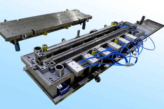
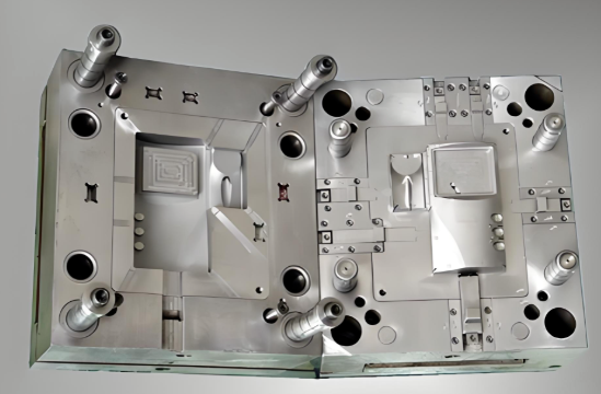
Tooling Design Specifications and Die Component Engineering
You've seen how to troubleshoot defects and optimize die performance. But here's the insight that separates reactive maintenance from proactive success: the decisions made during progressive die design determine 80% of your production outcomes. Material selection for die blocks, clearance specifications, stripper configurations—these choices lock in quality potential before the first part ever runs. Let's explore the engineering details that transform good dies into exceptional ones.
What makes metal stamping dies perform consistently across millions of cycles? It starts with understanding that every component serves a specific function, and compromising on any element cascades into production problems. According to Matcor-Matsu's die standards documentation, precision tooling requires specific material grades, hardness ranges, and dimensional specifications that leave nothing to chance.
Critical Die Components from Punch Plates to Strippers
Imagine building a house without understanding what each structural element contributes. Progressive die components work the same way—every piece plays a role in the finished product's quality. Here's what your tooling engineer knows but might not explain in detail.
Die blocks and shoes form the foundation. Lower and upper shoes typically use SAE 1018 or SAE 1020 steel for their combination of machinability and adequate strength. According to Matcor-Matsu standards, die shoe thickness should measure 90mm for standard applications, with 80mm acceptable for smaller dies. These dimensions aren't arbitrary—thinner shoes flex under load, causing dimensional variation and premature wear.
Punch and die inserts require harder materials that withstand repeated impact. AISI D2 tool steel hardened to 58-62 HRC handles standard materials effectively. But when stamping high-strength steels exceeding 550 MPa, DC53 steel provides superior toughness and wear resistance. Steel stamping dies see the harshest conditions, and material selection directly impacts maintenance intervals and part consistency.
Stripper plates serve multiple functions that casual observers miss. Beyond simply holding the workpiece during punch withdrawal, strippers maintain material flatness, guide punches into proper alignment, and prevent parts from lifting with the ascending punch. AISI 4140 steel provides the toughness stripper plates need to absorb repeated impact without cracking. Stripper pad thickness should measure at least 50mm—thinner plates deflect under load, causing misalignment and accelerated wear.
Pilot pins ensure precise strip positioning at every station. These hardened pins engage with pre-pierced holes, pulling the strip into exact alignment before any operation begins. Pilot pins with ejectors prevent material from lifting during strip advancement—a detail that eliminates misfeeds and positioning errors. Without proper piloting, cumulative errors would make tight tolerances impossible across multiple stations.
Backing plates support punches and prevent them from pushing into softer shoe material under high forming loads. According to industry standards, 4140 pre-hardened backing plates measuring 20mm thickness should back every trim punch, engaging 10mm before the actual cut begins. This seemingly small detail prevents punch deflection that causes burrs and dimensional variation.
| Component | Recommended Material | Hardness Range | Critical Specifications |
|---|---|---|---|
| Lower/Upper Shoes | SAE 1018 / SAE 1020 | As machined | 90mm thickness (80mm for small dies) |
| Trim Punches & Blades | AISI D2 or DC53 | 58-62 HRC | 10mm minimum width for 0.8-3.5mm material |
| Forming Inserts | AISI D2 or DC53 | 58-62 HRC | Split components over 300mm for maintenance |
| Stripper Plates | AISI 4140 | 28-32 HRC | 50mm minimum thickness |
| Backing Plates | 4140 Pre-hardened | 28-32 HRC | 20mm thickness, 10mm pre-engagement |
| Pierce Punches | M2 High-Speed Steel | 62-65 HRC | 90mm length with ball lock retention |
| Button Dies | M2 High-Speed Steel | 62-65 HRC | 25mm height standard |
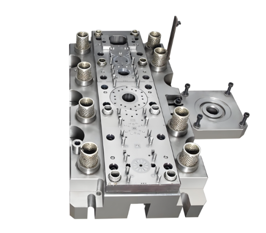
Design Considerations for Long-Run Production Dies
Designing progressive die tooling for 50,000 parts differs fundamentally from designing for 5 million. Long-run production demands features that add upfront cost but dramatically reduce total cost of ownership. Here's where the real engineering decisions happen.
Punch and die clearance affects everything from edge quality to tool life. The general rule specifies 5-10% of material thickness per side, but optimal clearance varies with material type and hardness. Tighter clearances produce cleaner edges but accelerate wear. Looser clearances extend tool life but increase burr formation. Finding the sweet spot requires understanding your specific material and quality requirements.
Guide systems maintain upper and lower die alignment through millions of cycles. Bronze bushings paired with solid guide posts measuring 80mm diameter (63mm for small dies) provide the precision and durability long-run production demands. Safety keepers prevent guide posts from pulling out during die separation—a simple feature that prevents catastrophic crashes.
Nitrogen gas springs have replaced mechanical springs in modern metal stamping die sets for forming and stripping applications. DADCO brand springs in appropriate series (Micro for small applications, L series for medium, 90.10-90.8 for large) provide consistent force throughout their stroke. Critical detail: charge nitrogen springs to maximum 80% capacity—75% is better for extended cylinder life.
When specifying progressive die tooling, engineers must define these key parameters:
- Material specifications: Base material grade, thickness tolerance, surface finish requirements
- Tonnage requirements: Calculated forming forces plus 30% safety margin for each station
- Strip layout dimensions: Pitch, width, carrier strip configuration, pilot hole locations
- Clearance specifications: Per-side clearance percentages for each cutting operation
- Station sequencing: Operation order optimized for material flow and carrier strip integrity
- Shut height and stroke: Die dimensions matching press specifications
- Sensor integration: Misfeed detection, tonnage monitoring, part presence verification
- Maintenance access: Provisions for punch replacement, die sharpening, stripper adjustment
Die complexity scaling follows part requirements—but not linearly. Simple flat parts with a few holes might need only 4-6 stations. Complex formed parts with multiple bends, embossed features, and precision holes can require 15-20 stations or more. Each additional station adds cost, maintenance requirements, and potential failure points. Experienced progressive die tooling designers minimize station count while ensuring each operation has adequate material support and forming clearance.
The relationship between die design and production speed deserves careful attention. According to Siemens NX documentation, motion simulation with dynamic collision detection helps verify correct operation across the entire range of die movements. Faster press speeds increase output but stress tooling components. Progressive dies designed for 60 strokes per minute may fail prematurely when pushed to 120 SPM without appropriate upgrades to springs, strippers, and guide systems.
Simulation and prototyping validate designs before committing to full production tooling investment. CAE simulation predicts material flow, springback, and forming stresses—catching problems that would otherwise require expensive die modifications. As Siemens notes, you can analyze material usage of the strip layout and press force balance, then simulate the strip progression before cutting any steel.
Modern progressive die design software enables:
- One-step unforming to develop flat blank shapes from 3D part geometry
- Formability analysis predicting thinning, wrinkling, and splitting risks
- Springback compensation built into die surfaces
- Strip layout optimization maximizing material utilization
- Kinematics simulation verifying clearances throughout the press cycle
Reusing proven designs accelerates development and reduces risk. According to Siemens, building reusable parts, registering them in custom libraries, and developing reusable die configurations streamlines subsequent projects. Sheet metal stamping dies for similar part families can share common elements—stripper configurations, pilot systems, guide assemblies—while customizing only the forming and cutting details.
The investment in proper progressive die components and thoughtful design pays dividends across the entire production lifecycle. Dies built to robust specifications run faster, produce more consistent parts, and require less maintenance than those designed to minimum acceptable standards. When evaluating tooling quotes, remember: the lowest upfront cost rarely delivers the lowest total cost. Specifications that seem excessive during quoting become essential during the millionth cycle.
Selecting a Progressive Die Stamping Partner for Your Production Needs
You understand die components, tolerance capabilities, and defect prevention strategies. Now comes the decision that determines whether all that knowledge translates into production success: choosing the right progressive metal stamping partner. This isn't about finding the lowest quote—it's about identifying manufacturers whose capabilities align with your specific requirements. The wrong choice costs far more in quality issues, delivery delays, and management headaches than any price difference could justify.
Here's what experienced buyers know: evaluating progressive die manufacturers requires looking beyond marketing claims to verifiable capabilities. According to industry sourcing guidance, quality management is the primary filter—a supplier lacking correct certifications represents a liability, not a cost saving. Let's build your evaluation framework systematically.
Evaluating Engineering Expertise and Simulation Capabilities
The best stamping die manufacturers solve problems before they reach production. How? Through engineering capabilities that catch issues during design rather than discovering them after tooling investment. When evaluating potential partners, dig into their technical infrastructure.
CAE simulation capabilities separate modern progressive stamping and fabrication operations from shops running on experience alone. Computer-aided engineering predicts material flow, springback behavior, and potential forming failures before cutting any tool steel. This matters because simulation-validated designs require fewer tryout iterations, reducing both time-to-production and total tooling cost.
Ask potential suppliers specific questions about their simulation practices:
- What CAE software do they use for formability analysis?
- Can they demonstrate springback compensation in their die designs?
- Do they simulate strip progression and material utilization before finalizing layouts?
- How do they validate simulation predictions against actual production results?
For context on what leading capabilities look like, consider that manufacturers like Shaoyi integrate CAE simulation throughout their design process, enabling them to achieve a 93% first-pass approval rate on new tooling. This benchmark indicates mature engineering processes that minimize costly iterations.
In-house tooling capabilities dramatically affect responsiveness. According to supplier evaluation best practices, if a die breaks during production, sending it out for repair can take days or weeks. A supplier with internal tool and die capabilities can often resolve issues in hours, keeping your just-in-time schedule intact. Ask whether they build dies internally or outsource—and what their typical repair turnaround time looks like.
From Rapid Prototyping to High-Volume Production Readiness
The gap between prototype capability and production readiness trips up many sourcing decisions. A supplier might deliver excellent sample parts but struggle with consistent high-volume output. Or they might excel at production runs but take months to develop initial tooling. Ideally, you want a partner managing the entire lifecycle.
Prototyping speed matters more than many buyers realize. Fast prototyping enables design validation before committing to production tooling, catching fit and function issues early when changes cost least. Some progressive die manufacturers deliver prototype quantities in as little as 5 days—a capability that accelerates your entire development timeline. Shaoyi, for example, offers rapid prototyping delivering 50 parts within this timeframe, demonstrating the benchmarks leading suppliers can achieve.
Production capacity assessment should verify equipment range and scalability. Key questions include:
- What press tonnage range is available? (100-600+ tons covers most automotive and industrial applications)
- Can they handle your projected annual volumes without capacity constraints?
- Do they run multiple shifts to support demanding delivery schedules?
- What backup capacity exists if primary equipment requires maintenance?
Use this comprehensive checklist when evaluating stamping die manufacturers:
| Evaluation Category | Key Questions | What to Look For |
|---|---|---|
| Quality Certifications | IATF 16949 certified? ISO 14001 environmental certification? | Current certificates verified with issuing bodies, not just "compliant" claims |
| Engineering Capabilities | CAE simulation? In-house die design? DFM feedback provided? | Documented simulation processes, design optimization examples |
| Prototyping Speed | Days to first samples? Prototype-to-production transition process? | 5-15 day prototype delivery, seamless handoff to production tooling |
| Production Capacity | Press tonnage range? Annual volume capability? Shift patterns? | Equipment matching your part requirements with growth headroom |
| Quality Performance | PPM rejection rates? First-pass approval rates? SPC implementation? | Rejection rates below 100 PPM, documented statistical process control |
| Tooling Maintenance | In-house die repair? Preventive maintenance programs? Spare parts inventory? | Internal tool room, documented maintenance schedules, rapid repair capability |
| Industry Experience | Similar parts produced? Industry-specific requirements understood? | Case studies demonstrating relevant experience, reference customers available |
Certification verification deserves special emphasis for OEM progressive stamping applications. While ISO 9001 establishes baseline quality management, IATF 16949 is the automotive industry standard specifically designed to prevent defects, reduce variation, and minimize waste. As CEP Technologies notes, they maintain both IATF 16949:2016 and ISO 14001:2015 certifications—the combination serious automotive suppliers require.
Be wary of suppliers claiming "IATF compliance" without actual certification. Compliance means following the standard's principles; certification means passing rigorous third-party audits verifying adherence. Always request current certificates and verify validity with the certifying body.
Quality performance metrics tell you what to expect in production. According to industry data cited by Shaoyi's supplier guidance, top-tier metal stampers achieve rejection rates as low as 0.01% (100 PPM), while average suppliers hover around 0.53% (5,300 PPM). This 50x difference translates directly into your scrap costs, line-down risks, and quality management overhead.
Ask for documented evidence of quality performance:
- Historical PPM rates over the past 12 months
- First-pass approval rates on new tooling (93%+ indicates mature processes)
- Customer scorecards from existing OEM relationships
- PPAP and APQP documentation examples demonstrating process rigor
Financial stability assessment protects your supply chain. In the era of just-in-time manufacturing, a stamper in poor financial health may struggle to purchase raw materials during market volatility. Look for suppliers reinvesting in equipment—servo presses, automated inspection, robotic handling—signaling long-term viability rather than running on depreciated assets.
The progressive stamping process demands partners who match technical capability with operational reliability. Whether you're sourcing automotive structural components or precision electronics terminals, the evaluation framework remains consistent: verify certifications, assess engineering depth, confirm production capacity, and validate quality performance with data. The suppliers who welcome this scrutiny are typically the ones worth choosing.
Frequently Asked Questions About Progressive Die Metal Stamping
1. What is progressive die in stamping?
Progressive die stamping is a metal forming process where sheet metal advances through multiple stations within a single die. Each station performs a specific operation—such as piercing, blanking, forming, bending, or coining—until the finished part emerges at the final station. The workpiece remains attached to a carrier strip that advances with each press stroke, enabling continuous, high-speed production of complex parts with tight tolerances and minimal handling between operations.
2. How much does a progressive die cost?
Progressive die costs typically range from $15,000 to $100,000 or more, depending on part complexity, number of stations, and material specifications. Average charges hover around $30,000 for standard applications. While initial tooling investment is higher than compound dies, the per-part cost advantage in high-volume production (50,000+ parts annually) quickly recovers this investment through reduced labor, faster cycle times, and minimal scrap rates.
3. What is the difference between progressive and transfer die stamping?
Progressive die stamping keeps the workpiece attached to a carrier strip throughout all operations, making it ideal for small to medium parts at high speeds. Transfer die stamping separates each blank from the strip and uses mechanical fingers to transport parts between stations. Transfer methods handle larger parts, deeper draws, and thicker materials (up to 0.500" or greater) that would tear a progressive carrier strip, but operate at slower cycle times.
4. What tolerances can progressive die stamping achieve?
Progressive die stamping routinely achieves tolerances of ±0.001" to ±0.005" for blanking and piercing operations, with premium tooling capable of ±0.0005". Bending tolerances typically range from ±0.25° to ±1°, while coining operations deliver the tightest precision at ±0.0005" to ±0.002". Achievable tolerances depend on operation type, material properties, die wear, and process controls like SPC monitoring.
5. What industries use progressive die metal stamping?
Automotive leads with transmission components, brake brackets, and electrical connectors requiring IATF 16949 certification. Electronics relies on copper progressive stamping for terminals, PCB connectors, and battery contacts. Medical device manufacturing demands biocompatible materials and cleanroom environments for surgical instruments and implantable housings. Aerospace uses aluminum progressive stamping for weight-critical aircraft components with material traceability requirements.