 Small batches, high standards. Our rapid prototyping service makes validation faster and easier —

Progressive Die Metal Stamping Guide: From Press Sizing To QA
Progressive Die Metal Stamping Made Clear
Imagine you need thousands—or even millions—of identical, precision metal parts. How do manufacturers deliver such high volumes with speed and accuracy? The answer often lies in progressive die metal stamping, a process that combines automation, repeatability, and efficiency in a way few other methods can match.
What Is Progressive Die Metal Stamping?
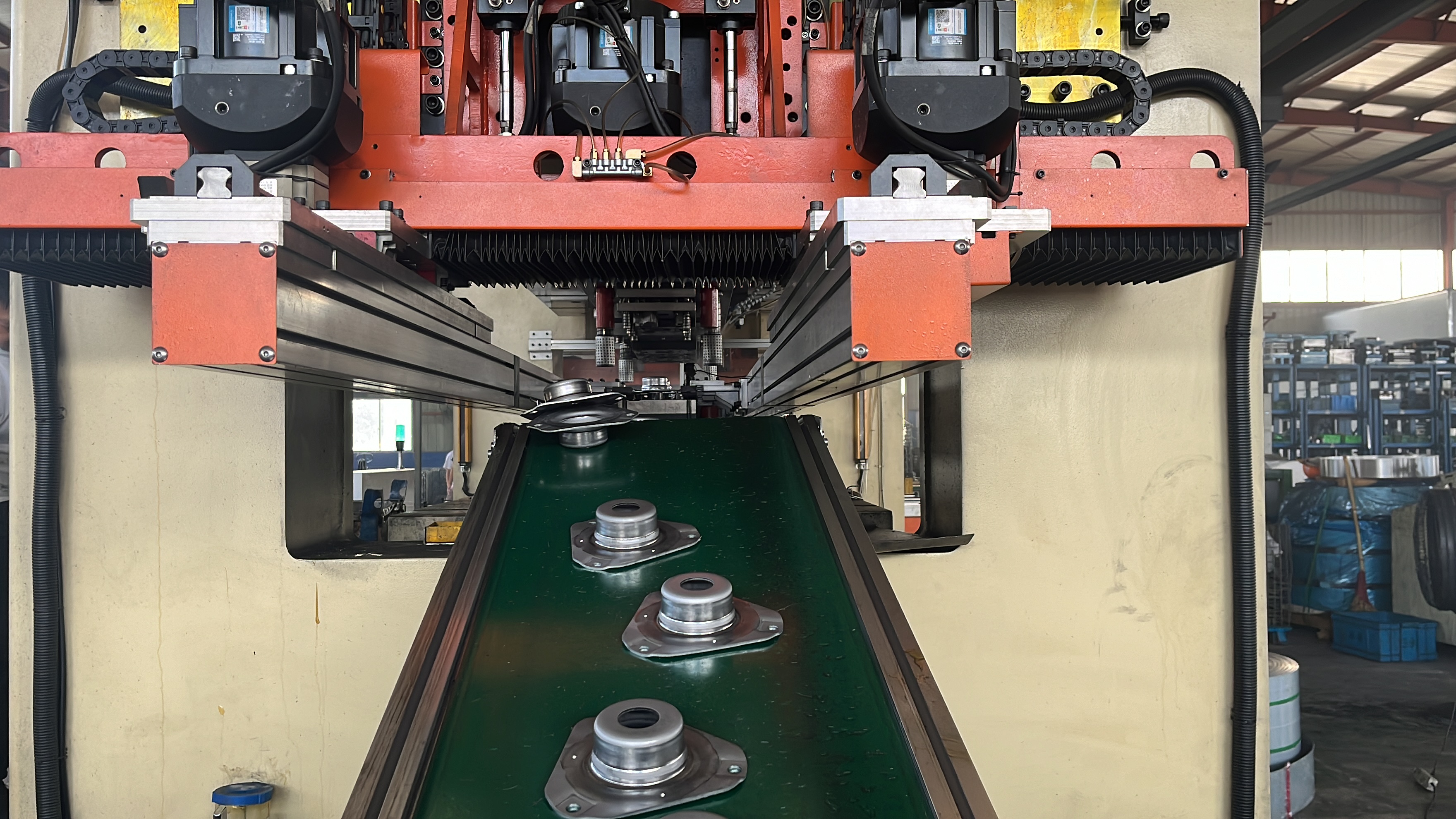
At its core, progressive die metal stamping is a highly automated manufacturing process where a coiled metal strip is fed through a series of workstations within a single die. Each station performs a different operation—such as piercing, bending, forming, or coining—so that with every press stroke, the strip advances and the part evolves step by step. By the time the strip reaches the end of the die, the finished part is cut free and ready for use. This approach allows for continuous, high-speed production of complex metal components with tight tolerances and minimal waste.
- High throughput: Each press stroke yields a completed part.
- Consistent tolerances: Precision dies ensure repeatability across large runs.
- Material efficiency: Optimized strip layouts minimize scrap.
- Integrated features: In-die operations like tapping, coining, or sensor insertion reduce secondary processing.
- Lower labor costs: Automation reduces manual handling and risk.
Progressive Stamping vs Transfer and Compound
When does progressive stamping outperform other methods? In transfer die stamping, the part is separated from the strip early and physically moved between stations, making it ideal for larger or more intricate parts but less efficient for high volumes of simpler shapes. Compound die stamping performs multiple actions in a single stroke, but is typically limited to flat geometries and lower production rates. Progressive die stamping stands out for:
- Superior cycle times for medium-to-high volume runs
- Better repeatability and precision for complex, small-to-medium parts
- Optimal material utilization versus transfer and compound methods
Think of progressive stamping as the go-to solution for automotive connectors, electronic terminals, and appliance components—any application where speed, consistency, and cost-per-part matter most.
Where Progressive Dies Deliver ROI
- The coil is loaded onto an uncoiler and straightened.
- The strip feeds into the die, guided precisely to the first station.
- Each station performs a dedicated operation—piercing, forming, bending, or coining.
- The finished part is separated from the strip at the final cutoff station.
- Parts are ejected, and the process repeats with every press stroke.
Key takeaway: Align your part’s geometry and production volume with the strengths of the progressive die stamping process. High-volume, moderately complex parts with consistent features are ideal candidates for progressive tooling. For production readiness, reference frameworks like AIAG PPAP and GD&T standards (ASME Y14.5) help ensure your design is optimized for reliable, repeatable stamping.
In summary, progressive die metal stamping delivers a unique blend of speed, precision, and cost-effectiveness—especially when compared to transfer die stamping and compound die stamping. When you need parts fast, with minimal waste and maximum consistency, the progressive die stamping process is often the best fit.
Press and Tooling Integration That Works
Ever wondered what makes progressive die metal stamping so reliable and repeatable? The secret lies in the seamless integration of the die with the stamping press—a combination of precision-machined components, robust alignment features, and careful setup procedures. Let’s break down how each element works together to ensure every press stroke delivers a flawless part, and how you can avoid the pitfalls that lead to downtime or scrap.
Inside the Progressive Die
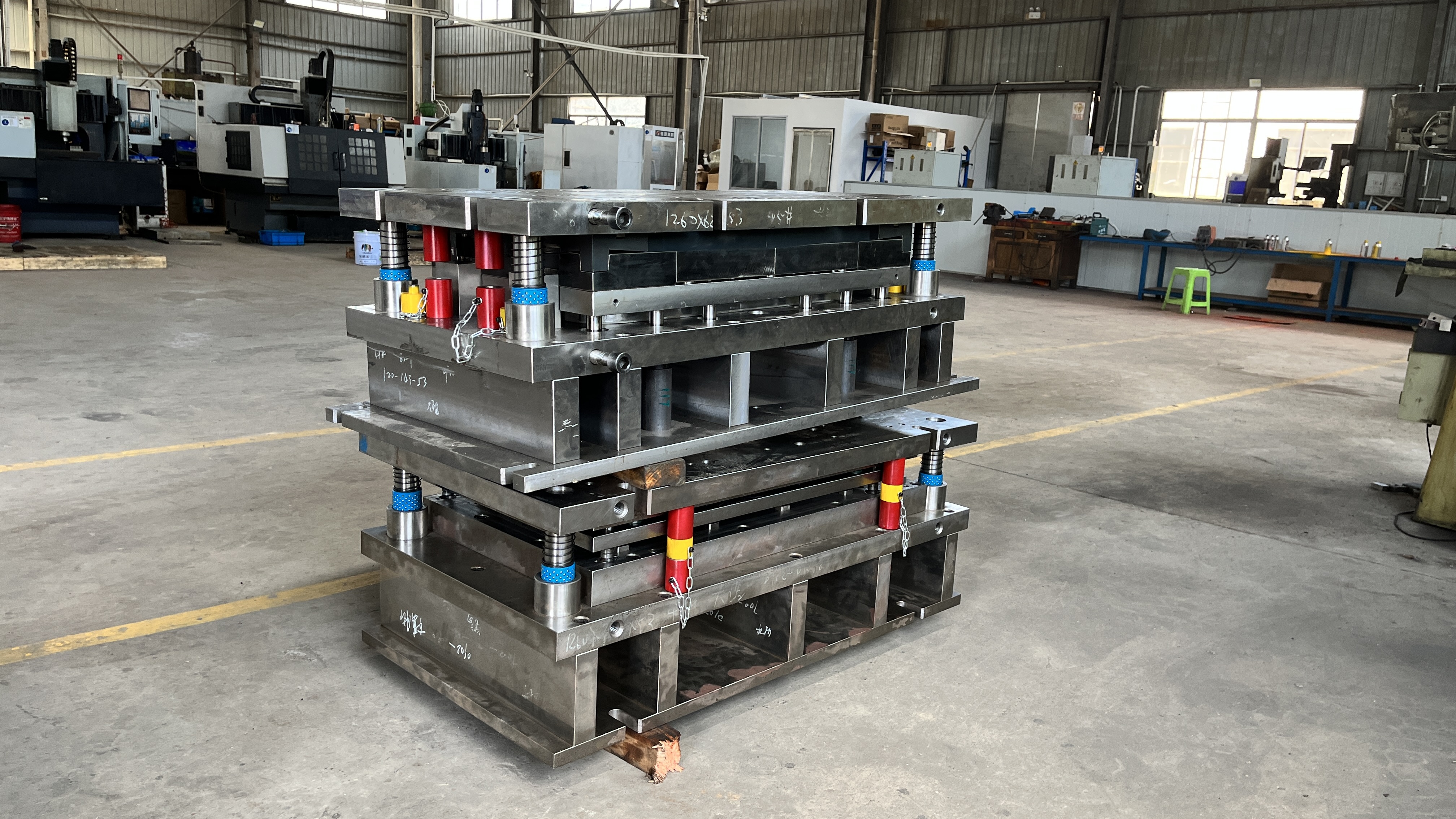
Picture a sheet metal die as more than just a block of steel. It’s a sophisticated assembly of upper and lower shoes, guide posts, punches, dies (buttons), pilots, lifters, strippers, springs or gas cylinders, cams, and sensors—all engineered to work in perfect harmony. Each part has a precise role:
| Subsystem | Main Function | Setup Notes | Common Failure Modes |
|---|---|---|---|
| Feed System | Advances coil strip accurately through stations | Align strip with die centerline; calibrate feed pitch | Misfeeds, strip skew, double feeds |
| Pilots | Precisely locate strip at each station | Pilots must be parallel to feed direction; verify engagement | Missed pilots, strip drift, hole elongation |
| Cams & Followers | Enable side actions (e.g., side pierce, emboss, flanging) | Check cam timing and lubrication; confirm follower travel | Sticking, misalignment, premature wear |
| Sensors | Monitor strip position, part ejection, and die closure | Test sensor function before production; set safe interlocks | False trips, missed faults, wiring failures |
| Strippers | Release part from punch after forming/cutting | Verify stripper force and parallelism | Incomplete part release, part sticking |
These components are the backbone of progressive stamping dies, each contributing to the overall stability and repeatability of the process. For instance, pilots keep the strip perfectly positioned at every station, while sensors catch misfeeds before they become costly crashes.
Press and Die Integration Essentials
It’s not just about having the right die—how you mount and set up the die in the sheet metal die press is just as critical. Here’s what you need to get right:
- Die Alignment: Ensure the die centerline matches the coil feed direction. Use keyways, locator pins, or positive stops for precise alignment.
- Shut Height: Set the press shut height higher than the die thickness during initial setup. Only calibrate to final shut height once the die is fully loaded with sheet metal to avoid damaging setup blocks [The Fabricator].
- Clamping: Use all clamping slots and verify that toe clamps apply pressure directly to the die shoe. Double-check all fasteners for tightness.
- Parallelism: Confirm the press ram and bolster are parallel to prevent uneven loading and premature wear on the stamping die.
Getting these basics right is the foundation for reliable, high-speed production with minimal downtime.
Feed Systems and Strip Control
Imagine the coil strip as a racecar on a track—it needs to stay precisely in its lane at every turn. The feed system, pilots, and guiding rails work together to ensure the strip moves smoothly and accurately through every station of the progressive dies. Any misalignment can cause jams, misshaped parts, or even catastrophic die crashes.
-
Cam/Follower Use Cases:
- Side piercing for features not aligned with the main feed
- Flanging operations that require lateral movement
- Embossing or forming features on the side of the strip
-
Best Practices:
- Regularly inspect and lubricate cams and followers for smooth operation
- Test all sensors before production runs and set up safe interlocks to halt the press if faults are detected
- Always keep the die and press surfaces clean and free of debris to maintain tight tolerances in the sheet metal die
By mastering these integration details, you’ll notice fewer setup issues, less scrap, and more consistent quality from your progressive stamping dies. Next, we’ll dive into how to select the right press and set process parameters to keep your production running smoothly and efficiently.
Process Parameters and Press Selection Blueprint
Sounds complex? Press sizing and process parameter selection for progressive die metal stamping doesn’t have to be overwhelming. By following a structured approach, you can match your prog die and press setup to the needs of your part and material, ensuring high-quality, efficient production. Let’s explore the key steps that help you avoid costly mistakes and maximize uptime in your metal stamping manufacturing process.
Method to Select Press Capacity
-
Characterize Material and Features
Begin by identifying your coil material—its thickness, width, tensile and shear strength, and any coatings that may affect formability or die wear. The type of operations (piercing, forming, drawing) and the number of features per part will influence station design and required forces. For example, high-strength steel or thick materials demand more tonnage from the progressive stamping press. -
Sum Station Forces and Add Safety Margin
For each station in the prog die, calculate the force required for its operation—piercing, bending, forming, blanking, etc. Use the perimeter, material thickness, and shear or tensile strength as appropriate:- Blanking/Piercing: Perimeter × Thickness × Shear Strength = Required Tonnage
- Drawing: Perimeter × Thickness × Ultimate Tensile Strength = Required Tonnage
-
Match Press Capacity and Bed Size
Select a progressive die press with a rated tonnage above your highest calculated load, ensuring the press bed and ram are large enough for the die footprint. Balance the die on the press so that forces are distributed evenly—off-center loading can increase wear and reduce tool life. Consider the deflection characteristics of the press; excessive deflection can cause uneven part quality and premature tool wear [IOP Conf. Series]. -
Set Feed Pitch and Target SPM
Determine the progression (feed pitch) based on part length and web requirements. The feed pitch, along with the press’s maximum safe speed, defines your target strokes per minute (SPM). Higher SPM increases throughput but may require adjustments to cam timing and strip handling. Make sure the feed system can keep up without causing jams or misfeeds. -
Validate Energy at Speed
It’s not just about peak tonnage—your press must deliver enough energy at the desired speed. A press may have sufficient tonnage but lack the energy to complete all operations at high speed, leading to jams at bottom dead center. Always check both tonnage and available energy for your cycle rate. -
Plan Scrap Carriers and Webbing
Design your strip layout to optimize material usage. Plan for scrap carriers and webbing that support the strip through all stations, minimizing waste while ensuring stability. Efficient web design improves yield and reduces material costs.
Feed Rates and Cycle-Time Drivers
Imagine you’re aiming for maximum output. The cycle time is driven by the slowest operation in your progressive stamping press. Factors that influence feed rates include:
- Material type and thickness (thicker or harder materials require slower speeds)
- Complexity of part features (more stations or deep draws may limit SPM)
- Feed system capability (mechanical vs. servo feeds)
- Strip stability and pilot engagement
Don’t overlook the impact of auxiliary operations, like in-die tapping or coining, which can also cap your maximum speed.
Tolerances, Yield, and Scrap Planning
How tight are your tolerances? The achievable precision in press progressive operations depends on die quality, press stability, and consistent strip control. Plan for:
- GD&T requirements—critical features may need additional restrike stations
- Yield optimization—tight strip layouts and minimal webbing boost material yield
- Scrap removal—ensure carriers and chutes are designed for smooth scrap ejection
When comparing with transfer press stamping or transfer presses, remember that progressive die setups typically yield higher throughput and material efficiency, while transfer stamping excels with large, deep-drawn, or unusually shaped parts.
Reminder: Press deflection and shut-height drift can significantly degrade hole quality and burr levels if not controlled. Modern simulation and deflection measurement tools can help you predict and compensate for these effects, reducing costly trial-and-error during tryout and production.
By following this blueprint, you’ll not only select the ideal progressive die press for your application, but also set the foundation for robust, repeatable results in your metal stamping manufacturing process. Up next, we’ll translate these process choices into actionable design-for-manufacturability rules for your strip layout, feature sequencing, and die design.
DFM Rules for Progressive Dies and Parts
When you’re designing for progressive die metal stamping, success hinges on the details you address long before the first coil hits the press. Sounds complex? It doesn’t have to be. By applying proven design-for-manufacturability (DFM) rules, you can minimize costly surprises, boost yield, and ensure your stamped parts meet both functional and cost targets. Let’s break down the essentials of progressive die design—from strip layout to station sequencing—using practical guidelines and real-world examples.
Strip Layout and Progression Planning
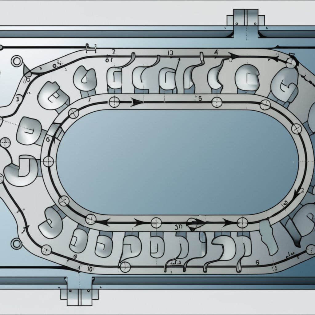
Imagine the metal strip as a roadmap for your part’s journey through the die. The way you arrange parts on the strip, set the feed pitch, and design carriers or webs directly impacts scrap, part accuracy, and tool durability. A well-thought-out strip layout is at the core of efficient progressive die tooling and is a key focus in any robust metal stamping die design [Progressive Die Stamping Design Guide].
- Optimize material usage: Arrange parts to minimize unused strip width and length, but always allow enough space for carriers, pilots, and safe clearances.
- Choose the right carrier type: Use center, inboard, outside, or one-sided carriers based on part geometry and forming needs. Carriers should be at least 2x material thickness for stability.
- Account for feed direction and grain: Sometimes, orienting the part at an angle to the grain reduces cracking or fatigue, especially for tight-tolerance features.
- Design for minimal lift: Keep the required strip lift between stations as low as possible to avoid misfeeds and vibration.
Clearances, Hole-to-Edge, and Feature Minimums
Ever wonder why some stamped parts warp or crack? It often comes down to ignoring minimum feature sizes or clearances in stamping die design. Here are some best practices, drawn from industry DFM guidelines:
- Holes and slots: Diameter should be equal to or greater than material thickness. Keep holes at least twice the thickness away from each other or the part edge.
- Bends: Minimum inside bend radius = material thickness. Height of bend = 2.5 × thickness + bend radius. Avoid bends too close to edges—add relief or offset as needed.
- Flanges: The minimum flange width is usually recommended to be 3 to 5 times the material thickness (3T-5T) to ensure stable forming and avoid material tearing.
- Embosses: Limit depth to 3 × material thickness to avoid thinning or fracture.
- Corners: Provide a radius of at least half the material thickness at blank corners.
| Feature Type | Design Notes | Gauging Considerations |
|---|---|---|
| Holes/Slots | Diameter ≥ material thickness; spacing ≥ 2× thickness from edge/other holes | Pin gages, optical comparators for position/size |
| Tabs | Width ≥ material thickness; avoid thin tabs near bends | Go/no-go gages; check for distortion after forming |
| Louvers/Embosses | Depth ≤ 3× thickness; avoid excessive stretching | Profile gages, visual inspection for thinning/cracks |
| Bends | Inside radius ≥ material thickness; relief notches near tight bends | Angle gages, check for springback |
Sequencing Stations for Stability
How do you decide the order of operations in progressive stamping die design? The answer is: prioritize strip stability and critical-to-function features. Here’s a practical approach:
- Keep datum features early: Punch critical holes or features that set datums at the first stations for best positional accuracy.
- Form after pierce: Always pierce or blank holes before forming or bending. This prevents distortion and maintains tolerances.
- Reserve restrike stations: Add restrike or coining stations after forming to tighten up GD&T-critical features.
- Trim after form where needed: When tight edge tolerances are required, trim after forming to clean up edges.
- Avoid thin webs near bends: Thin webbing can buckle or tear during forming; keep webs robust or add support features.
- Design pilot-friendly features: Use existing holes as pilots when possible, but avoid using tight-tolerance holes as pilots to prevent elongation.
DFM golden rule: Prioritize strip stability and consistent feed—even if it means adding extra stations. In progressive die metal stamping, a stable strip layout and robust support webbing are worth the investment for long-term process reliability and part quality.
By following these DFM rules in your metal stamping die design, you’ll find that progressive tooling becomes more predictable, maintenance is easier, and your stamped parts consistently meet both quality and cost expectations. Next, we’ll explore how material selection and forming strategies further reduce risk in your progressive die projects.
Materials and Forming Strategies That Reduce Risk
Ever wondered why some stamped parts stay true to their intended shape, while others warp or crack? The answer often comes down to material selection and how you approach forming each alloy in the progressive die metal stamping process. Let’s break down the science behind springback, sequence planning, and how coatings or surface treatments can make or break your next project—whether you’re working with steel stamping dies, copper progressive stamping, or the aluminum stamping process.
Springback Control Methods
Springback—the tendency of metal to partially return to its original shape after forming—can be a real headache, especially with high-strength or thin-gauge materials. Sounds familiar? You’re not alone. Here’s what you need to know:
- Yield Strength Matters: Materials with higher yield strength, like advanced high-strength steels or certain aluminum grades, are more prone to springback. This means carbon steel progressive stamping often requires extra compensation in die design or forming angle.
- Sheet Thickness: Thicker materials usually exhibit less springback, as they undergo more plastic deformation. If you’re stamping a thin copper or aluminum part, expect more elastic recovery.
- Geometry and Edge-Pressing Force: Complex shapes and U-forms are especially sensitive. Increasing edge-pressing force can help minimize springback by improving material flow and reducing internal stress differences.
- Mitigation Tactics: Common strategies include overbending (intentionally forming past the final angle), using restrike stations, or incorporating draw beads and cam forms for better control.
Forming Sequences for Challenging Alloys
Each material brings its own set of challenges. Wondering how to sequence operations for the best results? Compare the most common alloy families used in progressive die metal stamping:
| Material | Pros | Cons | Common Ops | Mitigation Tactics | Typical Applications |
|---|---|---|---|---|---|
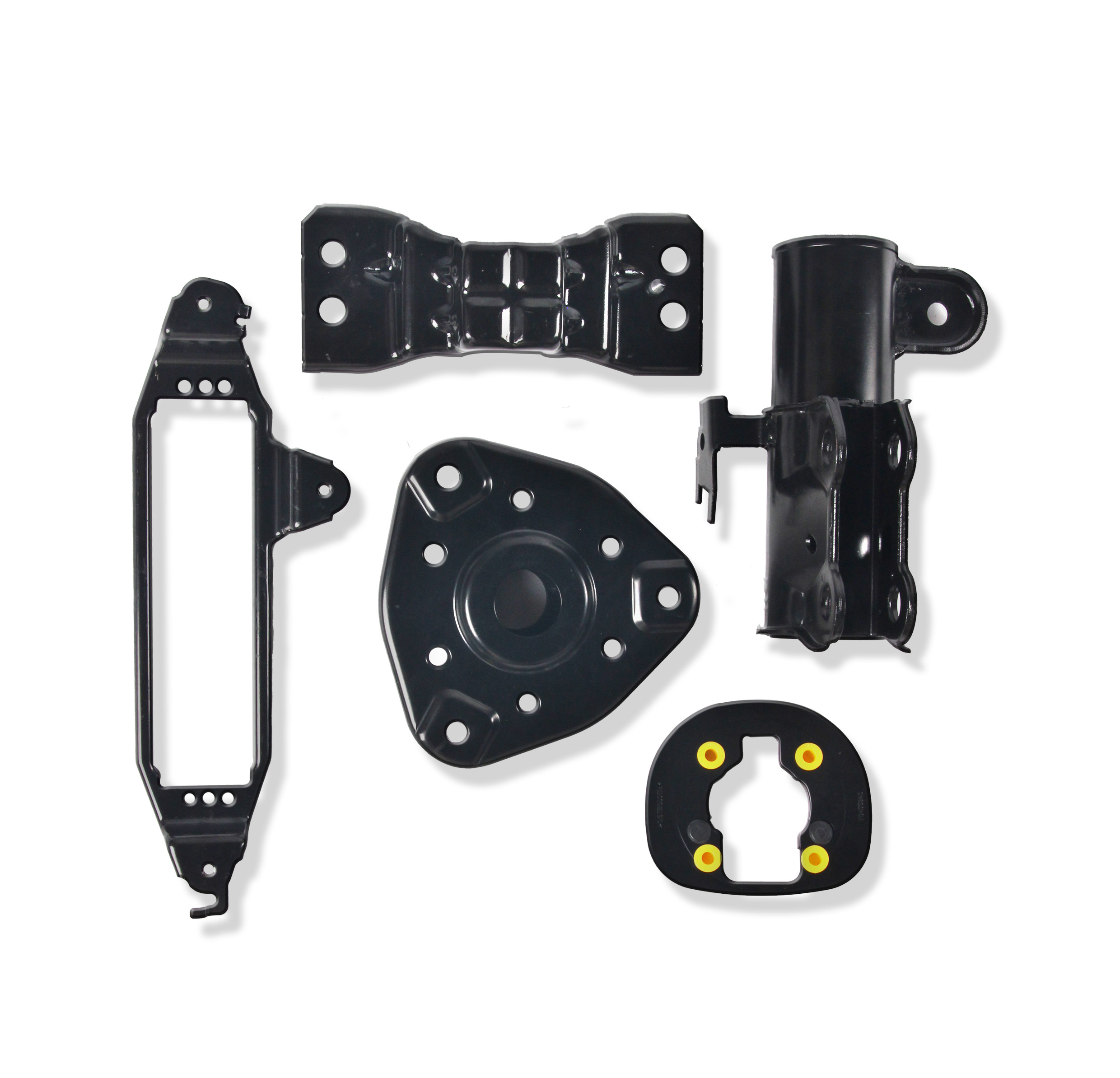
| Carbon Steel | Low cost, high strength, easy to form | Springback, rust risk | Pierce, bend, coin, emboss | Overbend, restrike, zinc plating | Automotive brackets, structural parts |
| Stainless Steel | Corrosion resistant, strong, smooth finish | Tool wear, work hardening | Pierce, deep draw, form | Carbide inserts, TiN coating, anneal | Medical, food, appliance parts |
| Aluminum | Lightweight, easy to form, good finish | Scratches, low strength, springback | Pierce, flange, emboss | High-polish dies, water-based lube | Stamped aluminum parts, electronics |
| Copper | Malleable, conductive, corrosion resistant | Soft, prone to burrs, oxidation | Pierce, form, coin | Anneal, nitrogen shield, restrike | Copper progressive stamping for connectors |
| Brass | Versatile, ductile, attractive | Stress cracking, oxidation | Pierce, form, emboss | Anneal, selective plating | Brass progressive stamping for hardware |
As you can see, the right forming sequence and die setup—restrike after forming, trimming after bends, or using special coatings—can make a major difference in part quality, especially for stamped aluminum parts and copper progressive stamping applications.
Coatings, Lubrication, and Surface Finish
Think coatings and lubricants are just for looks? Think again. They’re essential for reducing tool wear, preventing galling, and ensuring consistent surface quality:
- Plating: Zinc or nickel plating boosts corrosion resistance for carbon steel progressive stamping, while tin or silver may be used for copper or brass parts to improve conductivity or appearance.
- Coatings: Powder or organic coatings can add color, improve wear, or enhance lubricity. They’re especially useful for parts exposed to harsh environments.
- Lubrication: Water-based lubricants are preferred for the aluminum stamping process to avoid staining or residue. High-polish dies help prevent scratching on soft metals.
-
Alignment with Downstream Processes:
- Spot welding: Choose materials and coatings that don’t interfere with weld quality.
- Plating/e-coat: Plan for compatible base metals and surface prep.
- Burr direction: Control burrs to avoid issues in assembly or electrical contact.
- Grain orientation: Align critical bends or features with grain direction to maximize strength and prevent cracking.
By understanding these material and process strategies, you’ll not only reduce the risk of rejects but also ensure your progressive die metal stamping projects align with both performance and cost goals. Up next, we’ll show you how to lock in quality with robust inspection and quality control practices tailored to each material and part type.
Quality Control and Inspection That Scale
When you think about precision die stamping, what sets apart a flawless part from one that fails in the field? The answer is a robust, layered quality control system—one that starts before the first part is produced and continues through every stage of the manufacturing stamping process. Let’s walk through how industry leaders ensure that progressive precision metal stampings consistently meet demanding standards, from first article inspection to final data-driven release.
First Article Inspection Checklist
Imagine you’re about to launch a new run of stamping die components. How can you be sure the first parts off the press truly match the design intent? That’s where First Article Inspection (FAI) comes in—a structured process to validate every critical characteristic before ramping up production. According to best practices, an FAI should cover:
- Strip feed and pilot engagement—verify the strip advances correctly and pilots locate precisely
- Hole size and position—measure all pierced features for correct diameter and true position
- Bend angle and flatness—check that all forms meet angle and flatness requirements
- Burr height and directionality—inspect cut edges for burrs and confirm they’re oriented as specified
- Cosmetic zones—review visible surfaces for scratches, dents, or finish defects
- Feature-to-datum compliance—ensure all critical dimensions are within tolerance relative to datums
FAI isn’t just a one-time event. It’s repeated after any major die modification or process change, and documented in a formal report, often referencing IATF 16949 and AIAG PPAP standards for traceability and control plan alignment [SafetyCulture].
In-Process Gaging and SPC
Once production is underway, how do you maintain consistency for every part? In-process gaging and statistical process control (SPC) are the answer. These methods catch deviations early, reducing scrap and rework in the manufacturing stamping process. Here’s how feature types typically match up with gauging approaches:
| Feature Type | Gauging Approach | Notes |
|---|---|---|
| Holes (diameter, position) | Pin gages, optical comparators, CMM | Critical for progressive precision metal stampings; automated CMM or vision systems for high-volume |
| Tabs and slots | Go/no-go gages | Quick check for fit and functional clearance |
| Formed heights/angles | Height gages, protractors, custom fixtures | Monitor for springback or drift over time |
| Surface finish/cosmetics | Visual inspection, surface roughness testers | Essential for visible or plated parts |
| Datum-to-feature | CMM, vision system | Ensures alignment with assembly requirements |
SPC charts—such as X-bar and R charts—track key dimensions, revealing trends before parts drift out of spec. This is especially important for high-volume progressive die production, where early detection of tool wear or feed misalignment can prevent costly downtime and ensure the reliability of every stamping die component.
Data-Driven Release to Production
Before releasing a new part to full production, it’s essential to review all FAI and in-process data. Teams should confirm that measurement systems are capable (typically through a measurement system analysis, or MSA), and that control plans are in place per IATF 16949 or AIAG PPAP guidelines. Documentation should include:
- Material certifications and lot traceability
- Tooling and process change records
- SPC charts and capability studies
- Final inspection and release signatures
Tip: Lock your measurement system analysis before ramp-up. A capable, repeatable gaging process is the foundation for reliable quality in every phase of the manufacturing stamping process.
By combining these layered inspections and controls, you’ll ensure your progressive die metal stamping operation delivers consistent, high-quality results. Next, we’ll explore how smart tooling materials and preventive maintenance practices can help you sustain this quality over the long haul.
Tooling Materials, Coatings, and Maintenance Excellence
Ever wondered why some progressive die components last for millions of cycles, while others wear out after just a few runs? The secret lies in the careful selection of tooling materials, coatings, and a disciplined maintenance plan—especially as demands for higher output and tighter tolerances grow in today’s high speed stamping press environments. Let’s break down what goes into keeping your stamping tooling sharp, robust, and reliable.
Tool Steel and Coating Selection
Choosing the right tool steel for your stamping die punches and die components isn’t just about hardness. It’s about matching the steel’s properties to your production volume, material type, and the rigors of high speed stamping. Imagine you’re running silicon steel laminations or abrasive stainless at hundreds of strokes per minute—without the right steel and coating, you’ll face rapid wear and costly downtime.
| Tool Steel Family | Typical Use Case | Hardness (RC) | Coating Options | Notes |
|---|---|---|---|---|
| D-2 (High-Chrome) | Low-to-medium volume, general steel, some stainless | 60–62 | Titanium Nitride (TiN) | Good wear resistance, cost-effective for up to 2–3M hits |
| M-4 (High-Speed Steel) | Medium-to-high volume, abrasive or hard materials | 62–64 | Titanium Nitride (TiN), TiCN | Higher toughness, handles faster speeds and higher loads |
| Carbide (CD-260) | Ultra-high volume, electrical steel, high-abrasion jobs | 70–72 | Vanadium Carbide | Exceptional wear resistance, highest upfront cost |
For example, a D-2 steel punch heat-treated to 60–62 RC is suitable for up to 2–3 million hits in low-carbon steel. For higher volumes or when stamping abrasive alloys, M-4 high-speed steel (62–64 RC) offers longer life and better toughness. Carbide punches, though costly, can deliver up to 10 million cycles in demanding high speed stamping press operations, particularly with wear-enhancing coatings like vanadium carbide.
Wear-Part Replacement Strategy
Imagine your progressive punch wearing down mid-run—unexpected tool changes can halt production and kill OEE. That’s why a proactive wear-part strategy is critical. Here’s how you can plan ahead:
- Monitor punch and die button wear rates by tracking cycles and inspecting edge sharpness.
- Schedule regrinds or replacements based on historical data, not just visual cues.
- Stock critical spares for progressive die components to minimize downtime.
- Use CAE-driven formability reviews to identify high-wear areas in advance, refining clearances and tool geometry to extend life and reduce regrind frequency.
Suppliers who leverage advanced CAE simulation—like those backed by IATF 16949-certified processes—can help preempt wear hotspots and optimize your stamping tooling from the start. This approach not only reduces the number of regrinds but also shortens debug time, ensuring your high speed stamping lines stay productive and predictable.
Preventive Maintenance Cadence
Think maintenance is just about cleaning? Think again. A disciplined preventive maintenance loop is the backbone of long-term die reliability and part quality. Here’s a practical routine you can apply to any progressive die system:
- Cleaning: Remove debris and old lubricant after every run to prevent abrasive buildup.
- Inspection Checkpoints: Visually inspect for cracks, chipping, or uneven wear on punches, buttons, and strippers. Use advanced methods like ultrasonic or magnetic particle testing for subsurface flaws.
- Punch Regrind Triggers: Set cycle-based triggers for sharpening or replacing progressive punches based on historical wear data.
- Sensor Verification: Test all die sensors and interlocks before every production run to avoid costly crashes or missed faults.
- Lubrication Checks: Apply the correct lubricant for your operation—oil, grease, or dry film—tailored to the press speed and material. Check for contamination or breakdown.
Following this loop not only extends tool life, but also stabilizes quality and reduces the risk of unexpected breakdowns—especially vital in high speed stamping environments where even minor issues can generate large volumes of scrap in minutes.
Supplier Capability Checklist
When evaluating partners for progressive die metal stamping, consider these value-driven capabilities:
- CAE simulation for die design and wear prediction
- IATF 16949-certified maintenance documentation and traceability
- Rapid engineering collaboration for structural reviews and debug support
- Proactive preventive maintenance planning and training
- Comprehensive spare parts management for all progressive die components
By prioritizing these factors, you’ll ensure your progressive die metal stamping operation is built for sustained reliability—no matter how demanding your high speed stamping press schedule becomes. Next, let’s walk through a practical troubleshooting guide to keep your line running smoothly, even when defects arise.
Troubleshooting Common Progressive Die Defects
When your progressive die metal stamping line is running at full speed, even a small defect can quickly turn into a major headache. How do you pinpoint the root cause and fix it fast? Let’s walk through a practical troubleshooting guide—one that links the most frequent issues in the die process to their likely origins and corrective actions. Whether you’re new to stamping or a seasoned pro, these steps and solutions will help you get production back on track and keep quality consistent.
Defect-to-Cause Mapping
Imagine you notice burrs, torn edges, or misfeeds coming off your die-stamping machine. Where do you start? Use the table below as a quick reference for common defects, what might be causing them, and the best corrective actions. These patterns hold true across many types of stamping dies and are backed by industry troubleshooting experience:
| Defect | Likely Cause | Corrective Action |
|---|---|---|
| Excess Burrs | Punch/die wear, excessive or uneven clearance, misalignment | Regrind/replace punch or die, adjust clearance, check die alignment |
| Torn Edges | Incorrect clearance, dull tooling, material defects | Modify clearance, sharpen tooling, inspect/replace material |
| Misfeeds | Improper feed pitch, worn pilots, strip misalignment, feed system fault | Recalibrate feed/pilots, replace worn components, verify strip position |
| Angular Errors | Press shut height drift, ram not parallel, cam misalignment | Readjust shut height, check ram parallelism, revisit cam timing |
| Galling/Scuffing | Insufficient or wrong lubrication, rough die surfaces, material choice | Change lubricant, polish die, review material/lube compatibility |
| Springback Drift | Material property variation, inadequate forming control | Add restrike, adjust forming sequence, check material certs |
For certain stamping examples, you may also encounter jams, broken punches, or inconsistent part heights. Each of these issues often traces back to a handful of root causes—wear, setup, or material variation—underscoring the importance of a disciplined troubleshooting routine.
Stepwise Troubleshooting Flow
Sounds overwhelming? It doesn’t have to be. Here’s a simple, step-by-step flow you can use to triage most progressive die stamping issues:
- Confirm strip feed and pilot engagement—are strips advancing smoothly and pilots seating fully?
- Check punch and die condition—look for wear, chipping, or misalignment in the die stamping setup.
- Verify press shut height and ram parallelism—misadjustment here can cause angular errors or inconsistent cuts.
- Inspect sensors and cams—ensure all sensors are functioning and cams are properly timed and lubricated.
- Validate lubrication—use the correct type and amount for your material and speed.
- Review material certificates—confirm grade, thickness, and mechanical properties match the die process specs.
Following this sequence helps you isolate the issue quickly, minimizing downtime and scrap. For instance, if you’re seeing repeated misfeeds, double-check the purpose of bypass notches in stamping dies—these features can prevent overfeeding and help stabilize the strip, especially when edge camber or coil variation is present [The Fabricator].
Stabilizing the Process Window
Imagine you’ve fixed a defect—how do you keep it from coming back? Stability in the die process comes from regular maintenance, robust setup practices, and documenting every change. For example, if you adjust clearances or replace a punch, record the action and monitor results using SPC charts. This not only helps with traceability but also builds a knowledge base for future troubleshooting across different types of stamping dies.
Always document corrective actions and parameter changes. This ensures traceability and supports effective SPC correlation for long-term process control.
By following this troubleshooting guide, you’ll strengthen your ability to quickly resolve issues in progressive die metal stamping, keep your die-stamping machine running smoothly, and deliver consistent quality. Next, we’ll discuss how to select the right progressive die partners and make smart cost decisions for your stamping projects.

Vendor Selection and Smart Cost Decisions
Choosing the right partner for your progressive die metal stamping project can feel overwhelming. How do you know which supplier will deliver consistent quality, stay on schedule, and provide value throughout the lifecycle of your tooling investment? Let’s break down a practical approach to supplier evaluation and cost analysis—so you can make confident decisions for everything from prototype to mass production.
How to Evaluate Progressive Die Partners
Imagine you’re vetting potential progressive die manufacturers for a new automotive stamping dies project. What sets the top contenders apart? Here’s a step-by-step framework you can use to compare suppliers and avoid costly surprises down the road:
- Capabilities Match: Does the supplier handle your material range, part size, and station complexity? Can they support both high-volume and custom runs?
- CAE and Tryout Methodology: Do they use advanced simulation to optimize die design and predict material flow—reducing debug cycles and tooling costs?
- Certifications: Are they IATF 16949 or ISO certified? This signals a commitment to quality and robust process controls.
- Sample Lead Times: How quickly can they deliver prototypes or first-article samples? Do they have a track record of meeting launch deadlines?
- Maintenance and Repair Services: Is there a clear plan for preventive maintenance, wear-part replacement, and rapid die repair—especially if you’re running a high-speed or transfer stamping press?
- Communication Cadence: Will you have regular project updates, transparent reporting, and a single point of contact?
Shortlist of Supplier Capabilities
- Shaoyi Metal Technology — Offers IATF 16949-certified automotive stamping dies, advanced CAE simulation, and full lifecycle support from rapid prototyping to mass production. Their engineering team collaborates on transfer tooling, formability analysis, and maintenance planning, making them a strong, credible choice for complex automotive metal stamping process needs.
- Regional progressive tool & die specialists — May excel in niche materials or quick-turn projects, but check for depth in simulation and documentation.
- Large stamping dies manufacturer networks — Can provide global reach and scalable capacity, but consider lead times, communication, and local support.
When you’re comparing options, consider not only technical capability but also geography, lead time, and part complexity. For example, if your design requires both progressive and transfer tooling, choose a partner with demonstrated success across both processes, including transfer stamping press applications.
Tooling vs Per-Part Cost Decision
Wondering how to balance upfront investment with long-term savings? A simple amortization approach can help:
- Total Landed Tooling Cost: Add up the die build, tryout, delivery, and any transfer tooling or fixturing costs.
- Annualized Volume and Scrap: Estimate expected annual production and scrap rates to understand true output.
- Run Rate and OEE: Factor in press speed, uptime, and overall equipment effectiveness (OEE) to project capacity.
- Per-Part Cost: Divide total cost (including tooling amortized over projected volume) by usable parts produced.
- Compare Alternatives: Contrast with other processes—such as transfer stamping press or manual fabrication—for similar geometry and volume. Progressive die metal stamping typically delivers the lowest per-part cost at high volumes, while transfer tooling may be more flexible for complex or large-format parts.
While formulas can get detailed, this qualitative approach helps you see where the break-even point lies between initial tooling investment and long-term production savings.
From Prototype to Mass Production
Imagine launching a new part: you start with a prototype, validate with a pilot run, and scale up to full production. The best progressive tool and manufacturing partners guide you through each phase, offering design feedback, transparent cost breakdowns, and flexible support for both progressive and transfer tooling as your needs evolve. Look for a supplier who can adapt to your changing requirements and help you optimize the automotive metal stamping process from start to finish.
Key takeaway: A structured supplier evaluation and cost analysis framework helps you select the right partner and process—whether you’re investing in automotive stamping dies, transfer tooling, or scaling up a new progressive die project. Always align your choice with both technical needs and long-term cost targets.
Progressive Die Metal Stamping FAQs
1. What is a progressive stamping die?
A progressive stamping die is a specialized tool used in metal stamping that processes a coiled strip of metal through multiple stations within a single die. Each station performs a specific task—such as piercing, bending, or forming—so that with each press stroke, the strip advances and the part is incrementally shaped until it is cut free at the final station. This method is ideal for producing high volumes of precision parts efficiently and consistently.
2. How does progressive metal stamping work?
Progressive metal stamping involves feeding a metal coil through a series of precisely aligned stations in a die. Each station performs a unique operation, and the strip advances with each press stroke. The process is highly automated, allowing for rapid production of complex parts with strict tolerances and minimal waste. By integrating operations like piercing, forming, and even in-die tapping, manufacturers achieve high throughput and consistent quality.
3. What is the difference between progressive die stamping and transfer press stamping?
Progressive die stamping keeps the part attached to the strip throughout the process, advancing it through multiple stations in a single die for efficient, high-volume runs. In contrast, transfer press stamping separates the part from the strip early and uses mechanical or robotic transfer to move it between die stations. Transfer stamping is better suited for large or deep-drawn parts, while progressive die stamping excels at producing smaller, complex parts quickly and cost-effectively.
4. How do you choose the right material for progressive die metal stamping?
Material selection depends on the part's function, required strength, and downstream processes. Common choices include carbon steel for strength and cost-effectiveness, stainless steel for corrosion resistance, aluminum for lightweight applications, and copper or brass for conductivity. Each material requires specific forming strategies to control springback, burrs, and surface finish, and the choice impacts tool steel selection, lubrication, and die design.
5. What factors should you consider when selecting a progressive die stamping supplier?
Key factors include the supplier's experience with your material and part complexity, use of advanced CAE simulation, quality certifications like IATF 16949, lead times, preventive maintenance planning, and support for both rapid prototyping and mass production. Suppliers such as Shaoyi Metal Technology offer comprehensive capabilities, including in-depth engineering collaboration and robust maintenance documentation, ensuring efficient and reliable production.