 Small batches, high standards. Our rapid prototyping service makes validation faster and easier —

Steel Stamping Dies That Last: Cut Scrap, Downtime, And Cost
Getting started with steel stamping dies
Ever wondered how flat sheets of metal become the precise, complex parts found in cars, appliances, or electronics? It all starts with steel stamping dies—precision tools that shape, cut, and form metal into repeatable, high-quality components. Whether you’re new to manufacturing or looking to deepen your knowledge, understanding the basics of steel stamping dies sets the stage for success in any metal stamping process.
What is a die in manufacturing?
Let’s break it down: a die in manufacturing is a custom-engineered tool used to cut or form material, most often metal, into a specific shape or profile. In the context of metal stamping dies, these tools are usually made from hardened tool steel, designed to withstand repeated high-force operations. The die works in tandem with a press, using controlled force to shape sheet metal without introducing heat—a process known as cold forming. According to the ASM Handbook and industry guides, dies are the heart of stamping and pressing operations, translating designs into real-world parts.
Die, defined: A stamping die is a precision tool that cuts and forms sheet metal into a desired shape or profile, relying on the force of a press and carefully engineered tool steel sections. (Source: The Fabricator, ASM Handbook)
- Die set: The assembly holding the upper and lower die sections together for alignment in the press.
- Punch: The component that moves into the die cavity to cut or form the metal.
- Die: The stationary or lower part that shapes or supports the material.
- Stripper: Removes the sheet from the punch after each cycle.
- Guide pins: Ensure precise alignment of die halves during operation.
- Shut height: The distance between press ram and bed when the die is closed, critical for setup.
- Clearance: The gap between punch and die, tailored to material thickness and type for clean cuts.
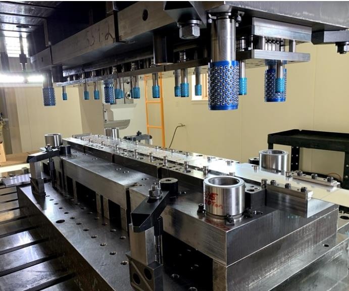
How steel stamping dies work
Imagine a giant cookie cutter—only far more precise. When a sheet of metal is placed in the press, the punch descends, pushing the material into or through the die. This action can cut (blanking, piercing), form (bending, drawing), or trim the metal. The magic of steel stamping dies is their ability to repeat this process thousands—even millions—of times, producing identical parts with tight tolerances. You’ll notice terms like die stamp and metal stamping dies are often used interchangeably for these tools and their process.
Stamping process overview
So, what is a stamping process, and where do dies fit in? Here’s a simple walkthrough:
- Design & Tooling: Engineers create a die design based on the desired part geometry.
- Material Preparation: Sheet metal is selected, cut, and leveled for feeding into the press.
- Blanking: The die cuts out the basic part shape (the blank) from the sheet.
- Piercing: Holes or slots are punched as needed.
- Forming/Drawing: The blank is bent or drawn into its final three-dimensional form.
- Trimming: Excess material is removed for clean edges.
- Finishing: Parts may be deburred, cleaned, or coated.
Each step relies on the right die and precise press setup. The metal stamping process is highly adaptable, making it essential in industries from automotive to electronics.
Mechanical vs. hydraulic presses: Why it matters
Not all presses are created equal. Mechanical presses use a flywheel to deliver fast, repeatable strokes—ideal for high-volume production of simple parts. Hydraulic presses, on the other hand, use fluid pressure for adjustable force and are better suited for complex shapes or thicker materials. The type of press influences die design, cycle speed, and even part quality. Choosing the right combination ensures efficient, cost-effective sheet metal stamping operations.
In summary, steel stamping dies are the backbone of modern manufacturing, converting design intent into tangible products through a series of well-orchestrated steps. By mastering these fundamentals, you’ll be ready to dive deeper into die types, materials, and advanced stamping and pressing strategies in the chapters ahead.
Choosing the right die type for your part
When you’re staring at a new part print or ramping up a new product line, the question always comes up: which stamping die is the best fit? With so many types of stamping dies—progressive, transfer, compound, and single-station—making the right choice can feel overwhelming. But once you understand the strengths and trade-offs of each, you’ll be able to align your die process with your business goals, whether that’s speed, flexibility, or cost control.
Progressive vs transfer vs compound dies
Let’s break down the main dies types used in modern metal stamping:
- Progressive Die: Think of this as an assembly line inside a single tool. The sheet metal strip advances through a series of stations, with each station performing a different operation—blanking, piercing, forming, and more. By the time the part exits, it’s fully formed. Progressive dies are ideal for high-volume runs of small to medium-sized parts that require multiple operations and tight repeatability. You’ll often see them in automotive clips, brackets, or electrical contacts.
- Transfer Die: Here, the part is separated from the strip early and moved (mechanically or robotically) from station to station. Each station can perform a unique operation—bending, drawing, trimming—making transfer dies perfect for larger or more complex parts, especially those needing deep draws or multiple bends. Transfer dies offer flexibility for intricate shapes but require more setup and careful coordination.
- Compound Die: This die type completes several operations (such as piercing and blanking) simultaneously in a single stroke at one station. Compound dies shine when you need high-precision, flat parts with tight tolerances, like washers or gaskets. They’re a go-to for medium-volume runs where speed and accuracy are key.
- Single-Station Die (Standard Die): Sometimes called a single punch or standard die, this is the simplest setup—one operation per cycle. It’s best for prototypes, low-volume jobs, or when you need to change the part geometry frequently. Single-station dies are quick to set up and cost-effective for short runs, but production speed and material utilization are limited.
| Die Type | Best For | Throughput | Changeover Complexity | Part Complexity | Initial Tooling Cost | Maintenance | Material Utilization | Automation Level |
|---|---|---|---|---|---|---|---|---|
| Progressive Die | High-volume, multi-operation small/medium parts | Very high | High (longer changeovers) | Moderate | High | Complex, requires expertise | High | High |
| Transfer Die | Large, complex, deep-drawn parts | Moderate | High (setup-intensive) | High | High | Complex, precision needed | High | High |
| Compound Die | Flat parts, tight tolerances | Moderate | Moderate | Low to Moderate | Medium | Moderate | High | Low to Moderate |
| Single-Station Die (Standard Die) | Prototypes, low-volume, flexible shapes | Low | Low (quick changeovers) | Simple | Low | Simple, easy to maintain | Low | Low |
When a single station die is the better choice
Imagine you’re developing a prototype or running a short batch where the part shape might change. The single-station die is your friend—easy to adjust, low cost, and quick to swap out. It’s also handy for jobs where you need to test different geometries or when your annual volume doesn’t justify a more complex die process. However, for larger runs or more intricate shapes, you’ll quickly run into limitations with speed and material yield.
Selecting a die type for your part mix
So how do you choose the right stamping die for your part? Use this checklist to match your needs to the right die architecture:
- What is the annual part volume? (High volumes favor progressive or transfer dies.)
- How complex is the part geometry? (Deep draws or multiple bends point to transfer dies.)
- What are your tolerance and finish requirements? (Compound dies excel at flat, precision parts.)
- How often will you change the part design? (Single-station dies are best for frequent changes.)
- What’s your budget for tooling and maintenance? (Factor in both upfront and ongoing costs.)
- What is the material thickness and type? (Some dies are better suited for specific materials.)
Key takeaway: The right die process balances part complexity, production volume, and cost. Progressive dies deliver speed for high-volume, repeatable parts; transfer dies offer flexibility for complex shapes; compound dies provide accuracy for flat parts; and single-station dies keep things simple and adaptable. Refer to technical guides from the Precision Metalforming Association (PMA) and "Metal Forming" by Altan for deeper insights.
As you weigh your options, remember that the right sheet metal die can dramatically impact your takt time, scrap rates, and total landed cost. In the next section, we’ll dig into how material and coating choices further extend die life and optimize your stamping operation.
Materials and coatings that extend die life
When you’re investing in steel stamping dies, the right material and coating choices can be the difference between weeks of downtime and years of reliable production. But with so many options—tool steels, coatings, surface treatments—how do you decide what’s best for your die processing needs? Let’s break down the essentials, using real-world examples and reference-backed insights to help you match die materials and coatings to your specific stamping die components and production goals.
Choosing tool steels for die components
Imagine you’re running millions of parts for automotive brackets or switching between mild steel and high-strength alloys. The tool steel you select for punches, die inserts, and wear plates will directly affect wear resistance, edge sharpness, and the overall life of your metal stamping die. According to AHSS Insights and The Fabricator, the most common options include:
- Conventional tool steels (like D2, A2, S7): Widely used for blanking and forming. D2 offers high wear resistance but can be brittle in severe applications. S7 provides great toughness for shock-loading but less wear resistance.
- Powder metallurgy (PM) tool steels: Engineered for a balance of toughness and wear resistance, especially when stamping advanced high-strength steels (AHSS) or running high volumes. PM steels can extend tool life up to tenfold compared to conventional grades in challenging applications.
- Carbide: Extremely hard and wear-resistant, ideal for thin-gauge or abrasive materials, but more brittle and costly—best reserved for high-speed, low-shock operations.
For aluminum stamping dies or when stamping softer metals, you may not need the extreme hardness of PM or carbide, but you’ll still want corrosion resistance and good machinability. Stainless tool steels or coated inserts can be a smart choice here.
Heat treatment and surface engineering
Sounds complex? Here’s the deal: the performance of your sheet metal stamping dies isn’t just about the base steel—it’s about how it’s processed. Heat treatment (hardening and tempering) unlocks the steel’s full potential, balancing hardness (for wear resistance) and toughness (to prevent chipping or cracking). For high-alloy tool steels, multiple temper cycles or even cryogenic treatments may be used to maximize performance.
Surface engineering—such as flame or induction hardening, nitriding, and PVD/CVD coatings—further enhances die life by reducing friction, galling, and adhesive wear. Each method has its strengths:
- Nitriding: Creates a hard, wear-resistant surface layer without the distortion risk of carburizing. Especially effective for high-wear areas and compatible with most tool steels.
- PVD/CVD Coatings: Thin, hard ceramic layers (like TiN, TiAlN, CrN) dramatically reduce galling and edge wear, especially when stamping AHSS or coated steels. PVD is often preferred for its lower process temperatures and minimal risk of die distortion.
- Carburizing: Used for creating a hard case on low-alloy steels, but less common for precision dies due to potential for dimensional change.
For metal stamping techniques that involve high contact pressures or abrasive materials, combining a tough substrate with a hard surface (through nitriding or coating) is a proven approach. Remember, proper heat treatment and surface finish before coating are critical for maximizing coating adhesion and effectiveness.
When to specify nitriding or PVD/CVD coatings
Not sure when to upgrade your die surface? Here’s a scannable guide:
| Part Material | Recommended Die Material | Surface Treatment/Coating | Best For |
|---|---|---|---|
| Mild Steel | D2, A2, or S7 tool steel | Nitriding or basic PVD (TiN) | General stamping, moderate wear |
| HSLA (High-Strength Low Alloy) | PM tool steel, toughened D2 | PVD (TiAlN, CrN) or ion nitriding | Higher strength, moderate to high wear |
| AHSS (Advanced High-Strength Steel) | PM tool steel (e.g., Z-Tuff PM®) | Multi-layer PVD (TiAlN, CrN), ion nitriding | Extreme wear, galling resistance, long runs |
| Stainless Steel | PM tool steel or carbide inserts | PVD (CrN), nitrided substrate | Corrosion, galling, abrasive wear |
| Aluminum Alloys | Stainless tool steel, coated inserts | TiN or TiC PVD coating | Corrosion resistance, clean edges |
Choosing the right combination isn’t just about part material. Consider production volume, die complexity, and your maintenance strategy. For example, high-run sheet metal stamping dies benefit from PM tool steels and advanced coatings, while short-run or prototype dies may use conventional grades with simpler treatments.
| Material/Coating | Pros | Cons | Machinability | Refurb Pathways |
|---|---|---|---|---|
| D2 Tool Steel | High wear resistance, easy to heat treat | Brittle in severe shock, limited for AHSS | Good | Regrind, recoat, insert replacement |
| PM Tool Steel | Excellent toughness, long life, suits AHSS | Costlier, requires precise heat treatment | Moderate | Regrind, insert swap, recoat |
| Carbide | Extreme hardness, edge retention | Very brittle, expensive, tough to machine | Poor | Insert replacement only |
| PVD Coating | Reduces galling, improves wear | Requires smooth substrate, may crack | Applied to finished die | Recoat after regrind |
| Nitriding | Hard surface, low distortion | Limited depth, not for every steel | N/A (post-machining) | Re-nitride after refurbishment |
Key takeaway: The best way to extend the life of your metal stamping die is to tailor both material and surface treatment to your part’s material, production volume, and stamping technology. Always verify compatibility—especially when running new alloys or advanced metal stamping techniques—and plan for refurb pathways that keep your tools in service longer.
By understanding these material and coating strategies, you’ll be ready to work with your die builder or maintenance team to reduce downtime, cut scrap, and get the most from your investment in sheet metal stamping dies. Next, we’ll walk through a practical workflow for stamping die design, so you can connect these choices directly to your next project.

A practical workflow for stamping die design
Ever faced a part print and wondered, “Where do I start with stamping die design?” You’re not alone. Whether you’re launching a new automotive bracket or refining a high-volume appliance part, a structured approach is the secret to success in metal stamping die design. Let’s break down a proven, step-by-step workflow—one that blends practical engineering with today’s digital tools—to help you move confidently from geometry to a robust, production-ready die for manufacturing.
From part print to die concept
It all starts with the part drawing. Before even opening your CAD software, review the part’s GD&T (Geometric Dimensioning and Tolerancing), material specifications, and any special requirements. Ask yourself: Is stamping the right process for this part? Does the geometry allow for cost-effective sheet metal stamping design—or are there features that could be simplified for manufacturability?
- Analyze the part print and specs: Identify critical features, tolerances, and materials. Look for sharp corners, deep draws, or tight bends that may complicate the die design.
- Select the appropriate die type: Decide between progressive, transfer, compound, or single-station dies based on part complexity, production volume, and budget (see previous section for a detailed comparison).
Clearance selection and springback planning
Once the die type is chosen, it’s time to focus on the details that drive quality and tool life. Two of the most critical are cutting clearance and springback compensation.
- Determine cutting clearances and edge conditions: The gap between punch and die must be tailored to the sheet’s thickness and strength. Too little clearance causes burrs and tool wear; too much leads to ragged edges. Reference material specs and industry standards to set these values.
- Plan forming stages and restrikes: For parts with bends, draws, or embosses, sequence the forming operations to minimize stress and avoid cracks. Sometimes, intermediate restrike stations are needed for precision or to manage complex shapes.
- Estimate springback allowances and compensation strategy: Metals don’t always stay put after forming. Springback—where the part tries to return to its original shape—can throw off tolerances. Use your experience or, better yet, digital simulation to predict and compensate for springback in the die geometry.
Press sizing and blank development
With the forming sequence mapped, you’ll need to make sure your sheet metal die press and feed system can handle the job.
- Calculate press tonnage, energy, and shut height: Estimate the forces required for cutting and forming. Confirm the die fits within the press’s shut height and that the tonnage is sufficient for the toughest operation. This ensures both safety and consistent part quality.
- Develop the flat blank and nesting layout: For stamping sheet metal, optimizing the blank shape and how it’s nested on the coil can save significant material cost. Use CAD to unfold complex parts and arrange blanks for minimal scrap.
- Create CAM-ready models and detail drawings: Finalize your digital models for all die components—punches, die plates, strippers, and guide pins. Generate manufacturing drawings and toolpath files for CNC, EDM, or other machining processes. This is where your metal stamping die sets come to life.
Minimum required inputs for stamping die design:
- Part CAD model and 2D drawings with GD&T
- Material type, thickness, and mechanical properties
- Annual and batch production volumes
- Required tolerances and surface finish
- Available press specs (tonnage, shut height, bed size)
- Preferred die type and process flow
How simulation and digital tryout reduce risk
Still worried about costly surprises during tryout? Modern CAE (Computer-Aided Engineering) tools are your new best friend. By running forming simulations—using finite element analysis (FEA)—you can:
- Predict formability issues (like splits, wrinkles, or thinning) before cutting steel
- Optimize blank shape and bead geometry for smooth material flow
- Accurately estimate press force and energy requirements
- Virtually compensate for springback, reducing trial-and-error in the shop
- Shorten physical tryout cycles and reduce material waste
For complex parts or advanced materials, digital tryout is now a standard step in stamping die design—saving both time and money.
| Design Decision | Analysis Tool | Key Outputs |
|---|---|---|
| Clearance & Edge Conditions | CAD, Standards Reference | Optimal gap, burr prediction |
| Forming Sequence/Restraints | CAE Forming Simulation (FEA) | Material flow, thinning, splits |
| Springback Compensation | CAE Simulation with Springback Module | Adjusted die geometry |
| Press Sizing | FEA, Empirical Calculation | Tonnage, shut height, safety margin |
| Blank Development | CAD Unfolding, Nesting Software | Flat blank size, nesting layout |
| Toolpath Generation | CAM Software | Machining code for die components |
By following this workflow, you’ll notice each decision builds on the last, creating a digital thread from initial concept to finished stamp die. It’s this systematic approach—combined with simulation and smart design choices—that leads to reliable, cost-effective metal stamping die sets for every project.
Ready to put your design into action? The next chapter walks you through tryout, setup, and troubleshooting—so you can move from digital model to high-quality stamped parts with confidence.
Tryout, Setup, Troubleshooting, and Maintenance
Ever wondered why some stamping shops run for months with minimal scrap, while others struggle with downtime and costly repairs? The answer often lies in disciplined tryout, smart setup, and proactive maintenance routines for your steel stamping dies. Let’s break down a practical, step-by-step approach you can use—whether you’re running a high-speed die-stamping machine or managing a small-batch stamping manufacturing process.
Die Tryout and Setup Checklist
Imagine you’ve just received a new metal stamping tool or completed a major die refurbishment. What’s next? A structured tryout and setup routine sets the foundation for reliable production and long die life. Here’s how to do it right:
- Press and Die Prep: Clean the press table and die seat thoroughly. Ensure all surfaces are free of debris for accurate alignment.
- Die Positioning: Center the die on the press bed for even force distribution. For dies with shanks, align precisely with the shank hole.
- Stroke Adjustment: Set the press to inching mode for controlled movement. Lower the ram slowly to bottom dead center, checking for smooth engagement.
- Clamping: Secure the upper die half first, then adjust the slider with a piece of scrap material matching your stamping thickness. Perform two or three dry hits before locking down the lower die.
- Feed, Pilots, and Sensors: Test the feed system, pilot holes, and all sensors. Confirm scrap ejection holes are clear and spacers are flat and aligned.
- Lubrication: Apply the correct stamping lubricant to reduce friction and prevent galling.
- First-Piece Approval: Run a single part, inspect for burrs, wrinkles, and dimensional accuracy. Only proceed to production after passing all checks.
Pro tip: A careful, stepwise setup not only prevents early tool wear but also minimizes costly adjustments during production. Never skip dry hits and blue-in checks—they reveal misalignment or interference before damage occurs.
Troubleshooting Common Stamping Defects
Even with the best setup, stamping metal process defects can arise. Here’s a quick guide to identifying and correcting the most frequent issues:
-
Burrs and Deformed Edges
-
Pros of corrective actions
- Sharpening or rehoning cutting edges restores clean shearing.
- Adjusting punch-to-die clearance reduces edge tearing.
-
Cons
- Too aggressive sharpening can shorten tool life.
- Incorrect clearance may cause new defects.
First, check for tool wear or misalignment before making major die adjustments.
-
-
Wrinkling
-
Pros
- Increasing binder force or optimizing blank holder pressure smooths material flow.
- Modifying die radii can reduce localized buckling.
-
Cons
- Too much pressure may cause splits.
- Changing radii might require new die components.
Do first: Adjust binder force and inspect for uneven material feed before altering die geometry.
-
-
Splits and Cracks
-
Pros
- Switching to material with better elongation increases formability.
- Smoothing punch and die radii prevents stress concentration.
-
Cons
- Material changes may affect cost or supply.
- Major die modifications add downtime.
Do first: Confirm material thickness and uniformity; then check die and punch radii for proper sizing.
-
-
Springback and Dimensional Drift
-
Pros
- Compensating die geometry can correct final part shape.
- Forming simulation helps predict and resolve issues before cutting steel.
-
Cons
- Geometry changes require careful validation.
First, measure actual springback and compare to simulation or previous runs before adjusting die profiles.
-
Maintenance Intervals and Refurbishment
Want to avoid unexpected downtime on your die stamping machine? A disciplined maintenance routine is your best defense. Here’s a sample maintenance schedule to keep your stamping tooling in top shape:
| Task | Frequency | Responsible Role |
|---|---|---|
| Visual inspection for cracks, wear, or debris | Daily | Operator |
| Lubrication check and application | Daily | Operator |
| Clean die surfaces and scrap removal paths | Shift-based | Operator |
| Edge regrind or sharpening | As wear is detected (weekly to monthly) | Tool Room Technician |
| Check alignment and shut height | Weekly | Setup Technician |
| Replace worn inserts, springs, or guides | As needed, based on inspection | Tool Room Technician |
| Document maintenance and repairs | Every event | All roles |
Following these intervals helps catch early signs of trouble—like burrs, increased tonnage, or out-of-spec parts—before they turn into costly breakdowns.
Key takeaway: Consistent tryout, setup, and maintenance routines are the backbone of a reliable stamping process in manufacturing. By addressing problems early and keeping your metal stamping tool in top condition, you’ll slash downtime, reduce scrap, and keep your stamping manufacturing process running at peak efficiency.
Up next, we’ll explore the bigger picture—how die lifecycle cost and refurbishment strategies shape your long-term ROI and keep your metal stamping operations competitive.
Die lifecycle cost and ROI essentials
When you invest in steel stamping dies, you’re not just buying a tool—you’re shaping the economics of your entire production metal stamping operation. But what really drives the cost of a manufacturing die, and how do you maximize its value over time? Let’s walk through the full lifecycle of a die, from initial build to refurbishment, and see how smart decisions can cut costs and boost your ROI in metal stamping manufacturing.
What drives tooling cost?
Ever wondered why the price tag on a new metal die set can vary so much? It’s all about the sum of many parts. Here’s what typically factors into the cost of dies manufacturing:
- Engineering & Simulation: The hours spent designing, modeling, and digitally testing the die. Complex parts or tight tolerances require more simulation and design effort.
- Machining die components: CNC machining, EDM (Electrical Discharge Machining), and grinding are used to create the precision shapes needed for each die section.
- Standard and specialty components: Guide pins, springs, sensors, and inserts—all add to the bill.
- Tryout and tuning: Multiple shop-floor cycles to dial in part quality and process reliability.
- Spare inserts and future-proofing: Planning for high-wear areas or quick-change modules can increase upfront cost but lower long-term maintenance.
Material choice, part complexity, and production volume also play a huge role. For example, a die designed for millions of cycles in a high-volume automotive dies production run will require tougher materials and more robust construction than a prototype tool. As noted in industry guides, investing in durable, well-designed tooling pays off in reduced downtime and lower per-part costs over the die’s life.
Expected die life and refurbishment paths
Imagine your die as a long-distance runner: with the right care, it can go the distance. What determines how long a metal stamping die remains productive?
- Part material: Harder or abrasive materials wear dies faster.
- Coating and surface treatment: Advanced coatings (like PVD or nitriding) can double or triple die life by reducing friction and galling.
- Lubrication and maintenance: Proper lubrication and routine checks prevent premature wear and sudden failures.
- Press condition and setup: Well-maintained presses and correct shut height settings reduce uneven wear.
- Operator discipline: Skilled operators catch problems early, preventing costly damage.
But even the best dies need periodic care. Instead of replacing a worn-out tool, consider refurbishment strategies that can restore performance at a fraction of the cost:
- Edge regrinding: Sharpening cutting edges to restore clean shearing.
- Insert swaps: Replacing high-wear sections without rebuilding the entire die.
- Weld repair and recut: Filling and machining worn areas to original specs.
- Recoat or re-nitride: Applying fresh coatings to extend life between major overhauls.
According to manufacturing best practices, regular inspections, timely maintenance, and die rebuilding can significantly extend tool life, minimize downtime, and reduce long-term capital expenditure (Sakazaki).
Make the business case for tooling: ROI and total cost ownership
So, how do you know if your investment in a new or refurbished die is paying off? It’s all about balancing upfront costs with long-term savings. Here’s a simple way to think about it:
- Amortize the initial tooling investment over the expected number of parts produced.
- Factor in direct costs: maintenance, refurbishment, and downtime losses.
- Compare the per-part cost to alternative methods (like laser cutting or machining) for your volume and quality needs.
- Don’t forget hidden savings: lower scrap rates, fewer line stoppages, and consistent part quality all add up.
Ultimately, the best ROI comes from dies that last longer, require less frequent overhaul, and produce quality parts with minimal rework—especially in high-volume metal stamping manufacturing environments. Investing in enhanced coatings or modular inserts may cost more upfront but often results in lower total cost of ownership over the die’s lifecycle.
| Tooling Strategy | Expected Uptime | Maintenance Effort | Total Ownership Cost | Refurbishment Pathway |
|---|---|---|---|---|
| Baseline (Standard Tool Steel) | Moderate | Frequent sharpening, regular checks | Lower initial, higher long-term | Edge regrind, weld repair |
| Enhanced Coatings (PVD/Nitriding) | High | Less frequent, mainly inspection | Higher initial, lower long-term | Recoat, re-nitride, minor regrind |
| Modular Inserts | Very High | Targeted insert swaps | Higher upfront, lowest over time for high wear | Insert replacement only |
Key takeaway: The smartest investment isn’t always the cheapest die—it’s the solution that delivers consistent uptime and lower per-part costs over the full lifecycle of your metal die set. Evaluate your dies production strategy with a focus on total cost of ownership, not just initial price.
As you plan your next production metal stamping project, keep these lifecycle and ROI factors in mind. Up next, we’ll help you choose the right stamping die partner—so you can align technical expertise with your business goals for every job.

How to select the right stamping die partner
When it comes to steel stamping dies, your choice of partner can make or break a project—especially in demanding fields like automotive, aerospace, or electronics. Ever found yourself weighing dozens of stamping die manufacturers, each promising quality and speed? Or maybe you’ve wondered how to spot a true tool metal stamping manufacturer from a generic supplier. Here’s a practical, step-by-step approach to help you narrow the field, compare vendors, and make a confident, informed decision for your next project.
What to look for in stamping die manufacturers
Imagine you’re sourcing a complex automotive stamping die. What separates a reliable partner from the rest? Start with these must-have capabilities:
- Engineering depth: Proven experience with similar parts, robust die design, and a track record in your industry (e.g., automotive die cutting).
- Advanced CAE simulation: Ability to model material flow, predict forming issues, and optimize die geometry before steel is cut.
- GD&T and tolerancing expertise: Demonstrated literacy in geometric dimensioning and tolerance management for precision die and stamping work.
- IATF 16949/ISO certifications: Essential for automotive and high-reliability markets.
- In-house machining/EDM: Direct control over tool build quality and speed.
- Die standards and spare strategy: Use of standard die components and clear maintenance pathways.
- Program management and PPAP support: End-to-end project tracking, documentation, and launch approval processes.
- Capacity and scalability: Ability to handle both prototype and mass production volumes.
As noted in industry checklists, a well-rounded stamping die factory should also demonstrate transparency, proactive communication, and a willingness to collaborate on engineering reviews.
Evaluating simulation and tryout capabilities
When you’re comparing progressive die manufacturers or partners for precision die and stamping, ask these questions:
- Do they use advanced CAE forming simulation (such as FEA) to model springback, thinning, and material flow?
- Can they provide digital tryout results or virtual part approval before physical tooling?
- How do they manage die tryout, first-piece validation, and process capability studies?
- Is there a structured feedback loop between your engineering team and theirs?
Some tool metal stamping manufacturers even offer full digital twins of the die, helping you catch issues before production. This is especially valuable for automotive stamping dies, where dimensional accuracy and surface finish are non-negotiable.
Quality certifications that matter
Certifications are more than just paperwork—they’re your assurance of repeatable quality and process control. For automotive stamping dies, look for:
- IATF 16949: The gold standard for automotive quality systems.
- ISO 9001: Broadly required for industrial and commercial applications.
- PPAP (Production Part Approval Process): Critical for automotive and aerospace launches.
Don’t hesitate to ask for documentation, audit results, or references. A reputable stamping die manufacturer will be transparent about their compliance and continuous improvement efforts.
Comparison table: Shortlisting your stamping die partner
To help you visualize the decision, here’s a comparative table of key capabilities across leading stamping die manufacturers. The first row features a partner with advanced automotive focus and IATF certification, illustrating the gold standard for projects demanding high quality and engineering support.
| Supplier | Automotive/Precision Focus | CAE Simulation | Certifications | In-House Machining/EDM | Program Management/PPAP | Spare & Refurb Strategy | Tryout & Digital Approval |
|---|---|---|---|---|---|---|---|
| Shaoyi Metal Technology | Custom automotive stamping dies, precision die and stamping | Advanced CAE, material flow prediction | IATF 16949, ISO 9001 | Full in-house machining & EDM | End-to-end support, PPAP, collaborative reviews | Standardized spares, proactive refurbishment | Virtual tryout, simulation-driven approval |
| StamForgeX | Automotive, electrical, progressive die manufacturers | In-house simulation, forming analysis | ISO 9001 | In-house die build | Project tracking, basic PPAP | Insert replacement, scheduled maintenance | Physical tryout, limited digital |
| KBear | Automotive, furniture hardware | Standard CAD/CAM | CE, SGS | Advanced stamping equipment | Custom project management | Spare parts on request | Physical tryout only |
| Quality Stamping & Tube Corp | OEM, aerospace, marine, appliances | Close tolerance, process controls | ISO 9001:2015 | High-speed, automatic stamping | OEM launch support | Custom spares, documented | First-article inspection |
| HULK Metal | Automotive, construction | CAD-based design | ISO, CE | Advanced equipment | Custom solutions | On-demand refurbishment | Physical tryout |
Key takeaway: The best stamping die partner is one whose technical depth, quality systems, and collaborative approach align with your part complexity, production volumes, and launch timelines. Use this table as a framework to score and compare potential suppliers—and remember, a true metal stamping die manufacturer will welcome your questions and site visits.
By following this guide, you’ll be equipped to select a stamping die factory or progressive die manufacturer that matches your needs, whether you’re sourcing for automotive die cutting, precision electronics, or high-mix industrial projects. Next, we’ll explore how to map these supplier choices to real-world applications and design-for-manufacture strategies for stamped steel parts.
Applications, Tolerances, and DFM for Stamped Steel
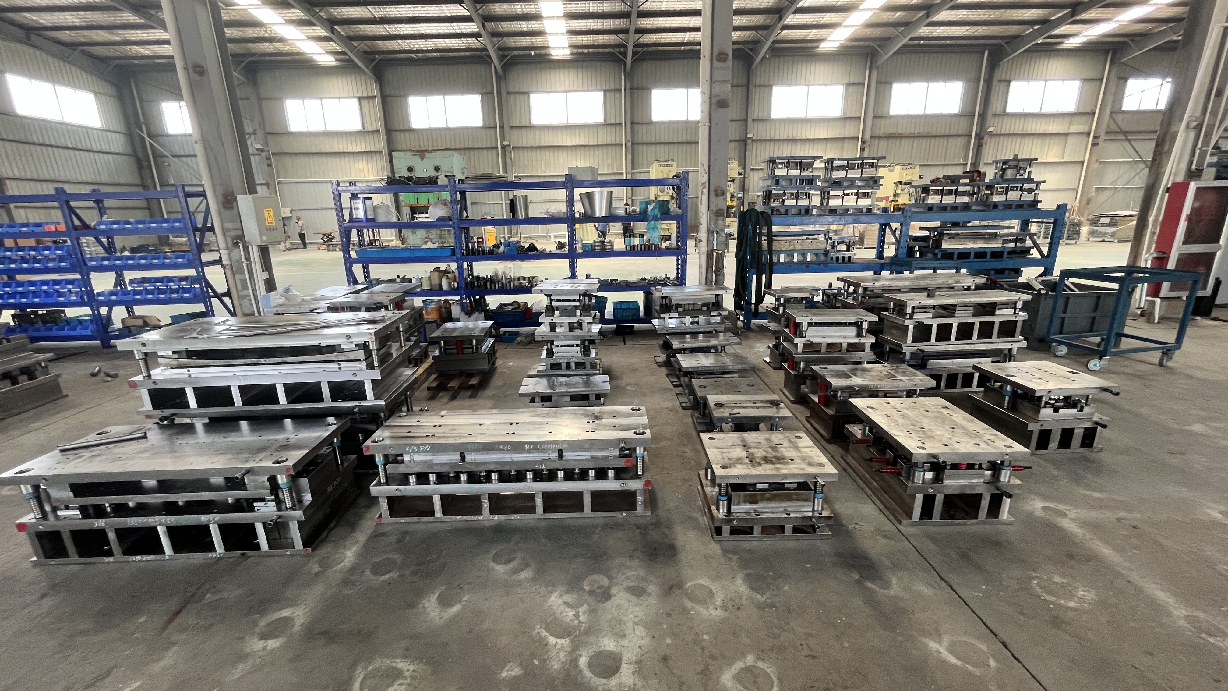
Typical parts made with steel stamping dies
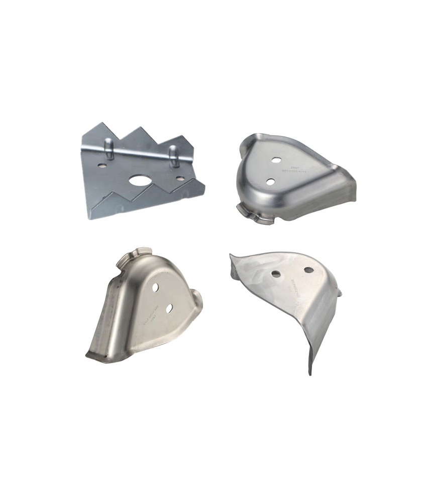
Ever wondered what products rely on stamped steel parts? Look around—chances are, you’re surrounded by them. Steel stamping dies are essential for high-volume production in industries like automotive, appliances, electronics, and construction. Here’s a quick snapshot of where stamped steel and stamped sheet metal truly shine:
- Automotive components: Brackets, reinforcements, seat frames, deep-drawn housings, and clips all begin as sheet metal stampings. The automotive stamping process often uses progressive or transfer dies for speed and repeatability.
- Appliance parts: Washer and dryer panels, mounting plates, and enclosure covers are commonly produced by steel sheet stamping for their clean edges and dimensional consistency.
- Electrical enclosures & hardware: J-boxes, terminal covers, and mounting brackets use stamped sheet metal for cost-effective, precise manufacturing.
- Building & medical hardware: Support brackets, wall plates, and medical device chassis are often made with steel stamping dies for strength and reliability.
Tolerance and surface expectations by process
Sounds precise? It is—but every stamping process has its limits. Unlike machining, sheet metal for stamping can’t always hold ultra-tight tolerances, especially across multiple bends or complex forms. According to industry guides, typical linear tolerances for punched features range from ±0.002" to ±0.020" depending on the process, die condition, and feature location (Five Flute). Bend tolerances depend on the material, thickness, and bend radius. According to relevant standards (such as GB/T 15055), unindicated angles typically range from ±0.5° to ±1.5°. For specific values, refer to the corresponding tolerance grade table. The cumulative error of multiple bends can be more complex and requires special attention.
- Punched features (holes, slots): Tightest tolerances, but depend on punch/die clearance and tool wear.
- Bent and formed areas: Tolerances relax with each bend—plan for additional clearance or floating hardware where alignment is critical.
- Drawn/deep-formed parts: Expect more variation in wall thickness and part geometry; surface finish may be impacted by lubrication and coating choices.
For automotive stamping process applications, consult OEM drafting standards to match tolerances and finishes to part function. Remember, specifying unnecessarily tight tolerances can drive up tooling and inspection costs without improving function.
Design-for-manufacture (DFM) considerations
Want to avoid cracks, warping, or costly rework? Smart DFM practices are your best defense. Here are proven features and guidelines to stabilize forming and boost yield in steel stamping dies:
- Bend radii: Keep inside bend radii at least equal to material thickness for ductile steels; increase for harder alloys to prevent cracking.
- Draw beads and reliefs: Use beads to add stiffness and control material flow; add bend reliefs to prevent tearing at corners or edges.
- Pilot holes: Place pilot holes away from bends (at least 2.5x thickness plus bend radius) to avoid distortion.
- Lubrication and coatings: For stainless or AHSS, specify appropriate lubrication and consider die coatings to prevent galling and maintain surface quality.
- Feature spacing: Keep holes and slots a safe distance from edges and bends (typically 1.5–2x material thickness) to reduce distortion.
- Assembly simplicity: Design parts to self-locate or use hardware like PEM inserts instead of welded joints when possible.
DFM takeaway: The most reliable stamping steel parts result from early collaboration between design and manufacturing—optimize radii, feature spacing, and tolerances to match real-world forming limits, not just theoretical CAD geometry.
By mapping your part’s function to the right die and process, and by applying these DFM principles, you’ll maximize quality and minimize surprises in your next sheet metal stamping project. Up next, we’ll wrap up with actionable resources and next steps to help you keep improving your metal stamping results.
Actionable next steps and trusted resources
Key takeaways and next actions
Ready to put your knowledge of steel stamping dies into action? Here’s a quick recap you can use as a checklist for your next project:By following this decision flow, you’ll not only reduce scrap and downtime but also position your team for success in any stamping and pressing operation. Remember, understanding what are dies and how they work empowers you to make smarter choices at every stage.
- Select the right die type: Match your part’s geometry, annual volume, and tolerance needs to the appropriate die—progressive, transfer, compound, or single-station. This is the foundation of what is die manufacturing and sets the tone for downstream quality.
- Choose materials and coatings wisely: Align your die steel and surface treatments with the part material (mild steel, AHSS, stainless, or aluminum) and expected run length. This step is critical for minimizing wear and extending tool life.
- Validate with CAE and simulation: Use digital tools to model forming, springback, and material flow before cutting steel. This reduces trial-and-error, saves time, and supports robust metal stamping design.
- Plan for tryout and maintenance: Implement structured setup, inspection, and maintenance routines to keep dies running smoothly and cut downtime.
Where to go for deeper guidance
Still have questions about what is stamping, die selection, or process optimization? There’s a wealth of vetted resources and expert guides available—whether you’re new to the field or a seasoned manufacturing engineer. Here’s a curated list to help you keep learning and improving:
- Shaoyi Metal Technology: Automotive Stamping Dies – For those seeking IATF 16949-certified automotive stamping die solutions, Shaoyi offers advanced CAE simulation, collaborative engineering reviews, and rapid tryout cycles. Their expertise in pressing and stamping aligns with the workflow and quality standards discussed throughout this guide.
- Precision Metalforming Association (PMA) – Industry-leading technical briefs, process capability guides, and training resources on all aspects of metal stamping design and manufacturing.
- ASM International – Authoritative handbooks and terminology references on what is metal stamping, die materials, heat treatment, and surface engineering.
- SME (Society of Manufacturing Engineers) – Comprehensive tooling and stamping technology guides, including best practices for die setup, troubleshooting, and lifecycle management.
- Larson Tool & Stamping: Metal Stamping Resources – Practical design guides, DFM checklists, and case studies for real-world sheet metal stamping projects.
Partnering for complex automotive stamps
When your next project calls for high-volume precision or the tight tolerances of an automotive stamping die, don’t go it alone. Partnering with a supplier who blends simulation-driven design, robust quality systems, and hands-on engineering support can make all the difference. Whether you’re launching a new vehicle platform or optimizing an existing line, leveraging the right expertise in metal stamping design and pressing and stamping technology will help you stay ahead of quality and cost challenges.
Curious about how to get started or want to benchmark your current process? Reach out to one of the vetted resources above, or consult with your preferred stamping die partner for a tailored roadmap.
Next step: Apply these strategies to your next die project, and use the listed resources to deepen your expertise in what is die manufacturing, what are dies, and the evolving field of metal stamping.
Frequently Asked Questions about Steel Stamping Dies
1. What is a die in metal stamping?
A die in metal stamping is a specialized tool used with a press to cut or form sheet metal into precise shapes. Made from hardened tool steel, these dies enable repeatable, high-quality production of metal parts by shaping, cutting, or forming the material through cold forming processes. The die's design directly translates part geometry into finished products, making it central to the metal stamping process.
2. What steel is commonly used for stamping dies?
Tool steels such as D2, A2, S7, and powder metallurgy (PM) grades are commonly chosen for stamping dies due to their balance of hardness, toughness, and wear resistance. The selection depends on the material being stamped and production volume. For example, D2 is preferred for general wear resistance, while PM steels are ideal for advanced high-strength steels or long production runs. Carbide and stainless tool steels are also used for specific applications like aluminum or abrasive materials.
3. How do progressive, transfer, and compound stamping dies differ?
Progressive dies perform multiple operations as the metal strip moves through a series of stations, making them ideal for high-volume, small-to-medium parts. Transfer dies separate the part from the strip early and transfer it between stations, suiting large or complex parts like deep draws. Compound dies carry out several actions in a single stroke, excelling at flat, high-precision parts. The choice depends on part complexity, volume, and tolerance requirements.
4. What maintenance is required for steel stamping dies?
Regular maintenance includes daily inspection for cracks and debris, lubrication, cleaning surfaces, edge regrinding as needed, alignment checks, and replacement of worn inserts or springs. Documenting all maintenance and repairs helps prevent unexpected downtime and extends die life. Proactive routines reduce scrap, improve part quality, and keep production running smoothly.
5. How do I select the right stamping die manufacturer for automotive projects?
Look for manufacturers with IATF 16949 or ISO 9001 certifications, advanced CAE simulation capabilities, in-house machining, and a proven track record in automotive or precision applications. Evaluate their engineering support, digital tryout processes, and spare part strategies. For example, Shaoyi Metal Technology offers custom automotive dies with CAE-driven optimization and collaborative engineering reviews, ensuring dimensional accuracy and efficient production.