 Small batches, high standards. Our rapid prototyping service makes validation faster and easier —

Transfer Die Stamping Secrets: When It Beats Progressive Dies Every Time
Understanding Transfer Die Stamping Fundamentals
When you're manufacturing complex metal parts that demand precision from every angle, not all stamping methods are created equal. While progressive die stamping keeps workpieces attached to a carrier strip throughout production, transfer die stamping takes a fundamentally different approach—one that opens up possibilities for geometries and operations that would otherwise be impossible.
Transfer die stamping is a metal forming process where individual blanks are mechanically transported between independent die stations using transfer fingers or grippers, allowing operations to be performed on parts in a free state without attachment to a carrier strip.
This distinction might sound subtle, but it changes everything about what you can achieve. According to Peterson Enterprises, transfer dies are "mainly used where the part has to be free from the strip to allow operations to be performed in a free state." This freedom is precisely what makes this process invaluable for certain applications.
What Makes Transfer Die Stamping Unique
Imagine trying to form a deep-drawn shell or add threading to a tubular component while it's still connected to a metal strip. Sounds impossible, right? That's exactly why transfer stamping exists. Unlike progressive die stamping, where the workpiece remains attached from start to finish, transfer dies liberate each part immediately after blanking.
Here's what sets this process apart:
- Independent part handling: Each component moves freely through the die-stamping machine, enabling operations on multiple sides
- Deep-draw capability: Without strip attachment restrictions, the press can punch as deep as the raw material allows
- Complex feature integration: Knurls, ribs, threading, and chamfers can be incorporated directly into primary press operations
- Versatile station configuration: A transfer die can function as a single die or multiple dies arranged in a production line
The Core Mechanics Behind Part Transfer Systems
So how does a part actually move through this system? The process begins when a strip of metal feeds into the first station, where the blank is cut free. From that moment forward, mechanical transfer fingers take over, carrying each part through various forming stations until completion.
What makes this mechanical choreography remarkable is its synchronization—all parts transfer to their next station simultaneously. This coordination enables transfer dies to handle large structural components, shells, frames, and tube applications that would be impractical with strip-based progression.
The versatility extends to part features as well. As noted by industry sources, "many part features such as pierced holes, chamfering, cut-outs, ribs, knurls and threading can be designed into primary press operations, eliminating the need for additional cost involved in many secondary operations."
For manufacturers weighing their options, understanding this fundamental difference between transfer dies and progressive die stamping is the first step toward selecting the right process for your specific part requirements.
The Complete Transfer Die Stamping Process Explained
Now that you understand what makes transfer die stamping fundamentally different, let's walk through exactly how this process unfolds—step by step. While competitors often gloss over these details with basic overviews, understanding each stage helps you appreciate why this method delivers such remarkable results for complex parts.
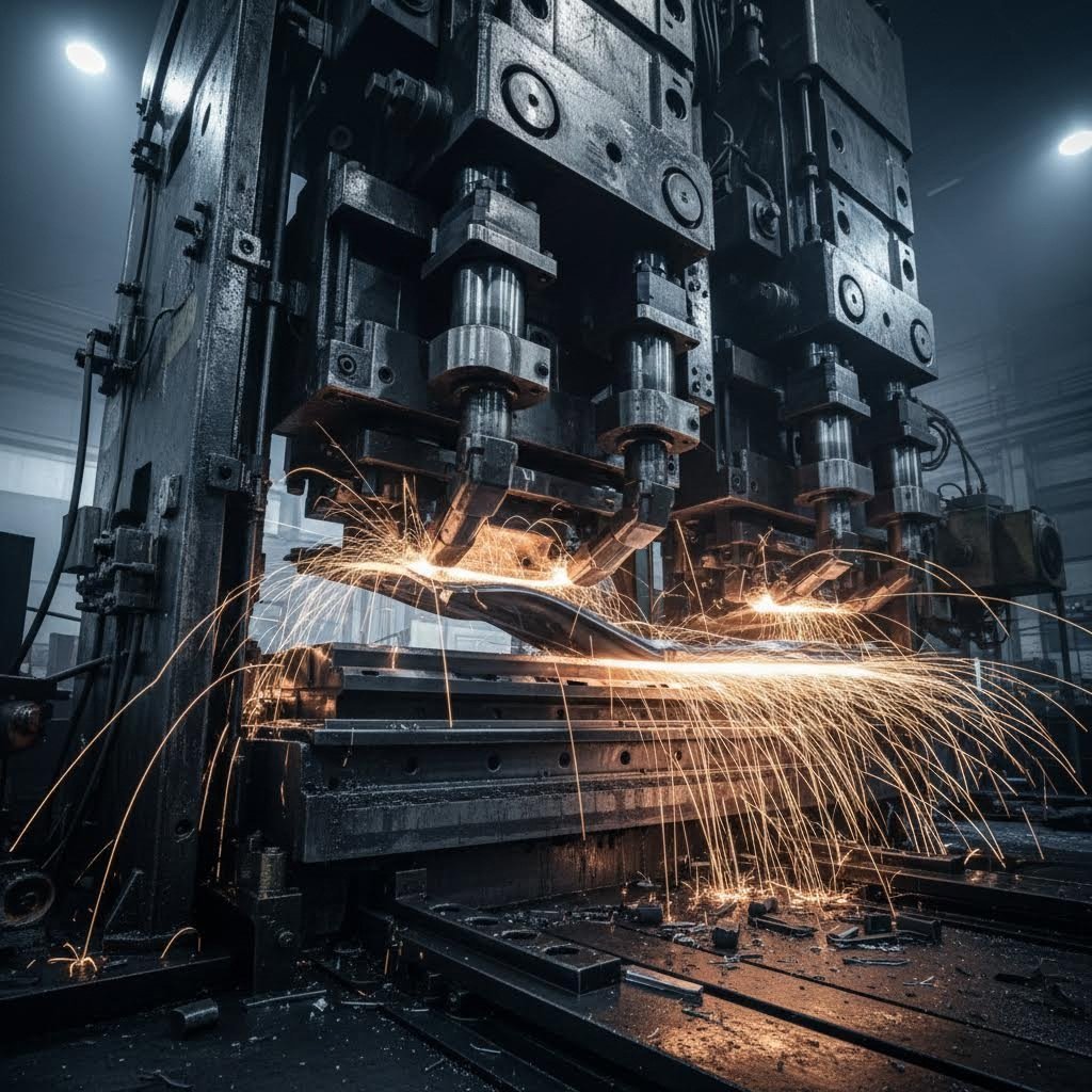
Picture a carefully choreographed production sequence where every movement is timed to the millisecond. That's the reality inside a transfer stamping press, where raw metal transforms into finished components through a series of precisely coordinated operations.
Stage-by-Stage Transfer Die Operations
The complete transfer die stamping sequence follows a logical progression from raw coil to finished part. Here's exactly what happens at each stage:
- Coil feeding and blank creation: The process begins with a heavy metal coil—sometimes weighing several tons—mounted on an uncoiler. According to U-Need's comprehensive guide, the raw strip feeds into the first station where a blanking die punches out the initial part shape. This moment marks the final connection between the workpiece and parent material.
- Part lifter engagement: As the press ram rises and the die opens, specialized part lifters raise the newly cut blank off the lower die surface. This elevation creates clearance for the transfer mechanism to engage.
- Mechanical gripper activation: Two transfer rails running the length of the die move inward simultaneously. Fingers or grippers mounted on these rails clamp firmly onto the blank's edges, securing it for transport.
- Vertical lift and horizontal transfer: With the blank locked in place, the entire transfer rail assembly lifts vertically, moves horizontally to the next station, and deposits the part with extreme precision onto the locators of the subsequent die. All this movement occurs within a fraction of a second.
- Sequential forming operations: The part progresses through multiple stations, each performing specific operations such as drawing, forming, piercing, trimming, or flanging. Unlike a die in progressive stamping where the strip constrains movement, the free-standing blank can be manipulated from any angle.
- Secondary operation integration: Many transfer stamping dies incorporate advanced secondary processes directly into the sequence—tapping heads for threaded holes, welding units for attaching brackets, or automated systems for inserting components.
- Final ejection and discharge: After the last station completes its operation, the transfer system grabs the finished part one final time and deposits it onto a conveyor belt or directly into shipping containers.
How Mechanical Grippers Enable Complex Part Movement
The transfer mechanism is where engineering precision truly shines. These systems typically use mechanical fingers or grippers mounted on synchronized transfer bars that operate in perfect harmony with press timing.
Consider what happens during a single press cycle. The Machine Concepts case study illustrates how sophisticated these systems have become: transfer beams use servo-driven rack and pinion mechanisms for horizontal movement and ball screw actuators for vertical positioning. End-of-arm tooling options include vacuum systems, mechanical grippers, or electromagnets depending on part requirements.
What makes this coordination remarkable is the simultaneous movement of all parts. When the press opens, every blank in every station transfers to the next position at the same instant. The grippers must:
- Engage precisely at designated pickup points without damaging partially formed features
- Maintain consistent grip pressure regardless of part geometry changes through the sequence
- Position parts within extremely tight tolerances at each station—often within thousandths of an inch
- Complete the entire pickup, transfer, and release cycle before the press begins its next downstroke
Some advanced transfer press stamping systems even incorporate servo rotation capabilities to flip parts between stations, enabling operations on both sides without manual intervention. This level of automation is why a single transfer stamping press can replace entire production lines that previously required multiple machines and manual handling.
The beauty of this process lies in its modularity. Each station within the stamping dies operates independently yet contributes to the whole. When one station needs modification or maintenance, engineers can address it without redesigning the entire tool—a significant advantage over monolithic progressive die designs where everything is interconnected.
With this detailed understanding of the mechanical sequence, you're now equipped to evaluate how transfer die capabilities compare directly against progressive die alternatives.
Transfer Die vs Progressive Die Stamping Comparison
You've seen how transfer die stamping works in detail, but how does it actually stack up against progressive die stamping when you're making real-world manufacturing decisions? The answer isn't simply "one is better than the other"—it depends entirely on your part's characteristics, volume requirements, and tolerance needs.
Let's break down the critical differences so you can make an informed choice for your next project.
Key Differences in Part Handling and Strip Requirements
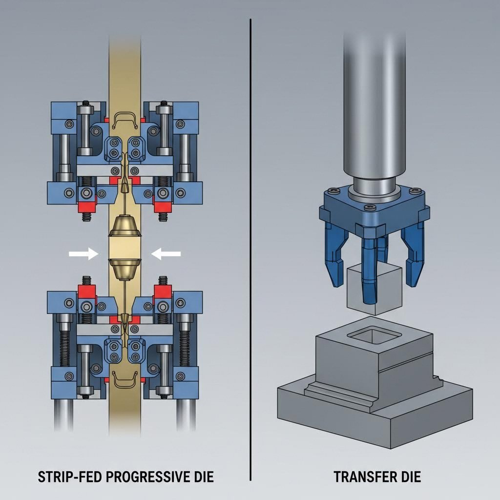
The most fundamental distinction between these stamping die types comes down to how they handle the workpiece during production. According to Engineering Specialties Inc., "progressive die stamping involves feeding a coil of metal through the stamping press that simultaneously punches, bends, and shapes the parts" while the workpiece stays connected to the base strip until final separation.
Transfer die stamping flips this approach entirely. The very first operation separates the blank from the strip, and from that point forward, the part travels freely through each station. This seemingly simple difference creates dramatically different capabilities:
- Progressive stamping: Parts remain tethered to the carrier strip, limiting how deep you can draw and which sides you can access
- Transfer stamping: Free-standing parts can be manipulated, rotated, and formed from any direction
For manufacturers working in die and stamping operations, this distinction often determines whether a part is even feasible with a particular method. Deep-drawn shells, tubular components, and parts requiring operations on both surfaces simply cannot stay attached to a strip throughout production.
When Part Geometry Dictates Your Die Choice
Imagine you need a part die stamped with threading on an interior surface, or a shell requiring multiple draw depths that exceed the strip's ability to stretch. These geometries make the choice for you—transfer stamping becomes the only viable option.
Here's a comprehensive comparison to guide your decision:
| Characteristic | Progressive Die | Transfer Die | Compound Die |
|---|---|---|---|
| Part Attachment | Remains on carrier strip until final cutoff | Separated immediately; moves freely between stations | Single-stroke separation; no station transfer |
| Suitable Geometries | Flat to moderately 3D; limited draw depth | Complex 3D shapes; deep draws; tubular forms | Simple flat parts; washers; basic cutouts |
| Production Speed | Highest (up to 1,500+ strokes/minute for small parts) | Moderate (typically 20-60 strokes/minute) | Moderate to high; depends on part size |
| Tooling Complexity | High; all operations integrated into single die | Moderate to high; independent stations offer flexibility | Lower; single multi-operation tool |
| Tolerance Capability | ±0.05 mm to ±0.1 mm typical | Tighter tolerances on complex 3D features possible | High precision for simple geometries |
| Typical Applications | Electrical contacts; brackets; small components | Automotive structural parts; shells; frames; tubes | Washers; simple flat stampings |
| Best Production Volume | High volume (100,000+ parts) | Medium to high volume; flexible | Medium to high for simple parts |
Notice something important about tolerances? Transfer dies often achieve tighter tolerances on complex 3D parts because each independent station can access the part from multiple angles. When a progressive die must work around the carrier strip, certain precision operations become geometrically impossible.
As Worthy Hardware's analysis explains, "Transfer Die Stamping is usually the preferred method for complex part designs due to its flexibility. Progressive die stamping is less suited for challenging parts but is excellent for simpler designs produced in large quantities."
Choosing Based on Volume and Complexity
The decision matrix becomes clearer when you consider both complexity and volume together:
- High volume + simple geometry: Progressive die wins on speed and per-part cost
- High volume + complex 3D features: Transfer die delivers capability progressive simply cannot match
- Medium volume + flat parts: Compound die offers efficiency with lower tooling investment
- Any volume + deep draws or multi-side operations: Transfer die is often your only realistic option
The economics shift at different production scales too. Progressive stamping demands higher initial tooling costs but delivers lower per-part expenses at volume. Transfer stamping involves higher operational complexity but provides unmatched flexibility for intricate designs and shorter runs.
Understanding these tradeoffs prepares you to evaluate the design considerations that will ultimately determine your tooling success.
Design Considerations for Transfer Die Tooling
So you've determined that transfer tooling is the right approach for your project. Now comes the critical question: how do you design it correctly? The decisions made during the design phase determine everything—production speed, part quality, maintenance requirements, and ultimately your cost per piece.
Unlike progressive die tooling where the strip itself guides part movement, transfer die design requires careful orchestration of independent elements. According to The Fabricator, a designer needs several critical pieces of information before beginning: press specifications, transfer specifications, part specifications, and miscellaneous details about quick die change systems and lubrication requirements.
Let's explore the factors that separate successful transfer die designs from problematic ones.
Critical Strip Layout and Station Spacing Decisions
Before any metal gets formed, engineers must determine how material enters the system and how many stations the part requires. This isn't guesswork—it's a calculated analysis based on forming complexity and press constraints.
The first major decision involves material loading method. You have three primary options:
- Coil feed: Works well with square or rectangular blank shapes but can result in inefficient material use with irregular geometries. A zig-zag feed system sometimes improves material utilization by nesting blanks on the strip.
- Coil/transfer hybrid: Combines a coil-fed progressive die for blanking operations with a transfer system for remaining stations. This eliminates the need for a blank destacker but may use material inefficiently with some shapes.
- Blank destacker: Offers the most efficient material use because blanks can be nested in various configurations during separate blanking operations. This approach also eliminates one or more stations in the transfer die itself.
Station spacing—the "pitch length" in industry terminology—directly affects what press you can use. Here's the calculation that determines feasibility: multiply the number of required stations by the pitch length. If this exceeds your press bed capacity, you need a different press or must consider off-line operations.
The pitch length itself is usually dictated by blank dimensions. As industry experts note, "for maximum speed and because of press space constraints, dies are located as closely together as possible, and, ideally, the parts are oriented with the shortest dimension in the pitch axis."
This orientation decision also connects to steel grain direction. If you're using coil feed, the grain orientation may result in excessive material loss. Sometimes the grain must go in one specific direction because of part length relative to available coil widths—a constraint that carbon steel progressive stamping operations face regularly.
Designing for Reliable Part Orientation
When a transfer system deposits a part at each station, that part must land in exactly the right position—and stay there until the die closes. This sounds simple until you consider that orientation requirements often change from station to station.
According to progressive tool and manufacturing best practices adapted for transfer applications, several factors govern part orientation decisions:
- Blank size and shape: Larger blanks require more robust gripper engagement and may limit transfer speed due to inertia
- Draw depth requirements: Deep draws may require part reorientation between stations to access different surfaces
- Material springback compensation: Engineers must account for how material "relaxes" after forming, designing subsequent stations to correct or work with this behavior
- Pilot hole placement: Precisely located holes punched early in the sequence can serve as registration points for accurate positioning throughout remaining operations
- Burr locations: Parts may need rotation to ensure burrs form on acceptable surfaces
- Forming access angles: Sometimes a small amount of tilt allows a punch to go squarely through material rather than hitting at an angle—reducing side loading and potential punch breakage
The two-axis versus three-axis transfer decision significantly impacts orientation capabilities. A two-axis transfer needs supports between operations to allow parts to slide—limiting which geometries work. Parts resembling a helmet or hubcap with flat bottoms can slide on bridges between stations. Other shapes tend to tip during sliding and require three-axis systems that lift parts completely clear.
For three-axis systems, the part shape itself often helps maintain location. Cone-shaped parts, for example, automatically and accurately nest in proper positions. But not every geometry is so cooperative—some require hold-down pins that keep the part positioned when grippers retract and continue holding until the die traps the workpiece.
Gripper Engagement and Finger Design
The transfer fingers represent one of the most critical—and often overlooked—design elements. These components must grab partially formed parts without damaging delicate features, maintain grip through high-speed movement, and release precisely at each station.
Key gripper design considerations include:
- Pickup point identification: Each station requires accessible locations where fingers can engage without interfering with formed features
- Weight and inertia management: Part weight determines acceleration and deceleration limits. Excessive weight limits peak speeds and affects final average transfer time
- Finger material selection: Many transfer designers use high-strength, lightweight materials such as aluminum or UHMW urethane for part-contact fingers—minimizing inertia while eliminating die damage if fingers get caught during tryout
- Return path clearance: The finger return path is critical. Clearance between fingers and die components during the return stroke must be verified to prevent interference. Mechanical transfers are especially unforgiving—servo systems can vary return profiles to create more clearance possibilities
Feed line height determination happens simultaneously with orientation planning. The goal is minimizing transfer distance to maximize system speed while ensuring satisfactory pickup points exist at all stations—both before and after each stamping operation. Lifters must be provided to allow finger access without losing part location or control.
Scrap removal planning also affects station layout. Small trim pieces must be disposed of quickly and automatically. Design experts recommend adding idle stations near scrap chutes to keep pitch length short—but only if press length accommodates extra stations.
These design decisions interconnect in complex ways. A change to gripper engagement points might affect station spacing, which impacts press selection, which influences production speed targets. Successful progressive stamping die design for transfer applications requires considering all these factors simultaneously rather than sequentially.
With proper design fundamentals established, the next consideration becomes material selection—because even the best-designed tooling fails if the material properties don't match the process requirements.
Material Compatibility Guide for Transfer Die Stamping
You've got your transfer die design dialed in, but here's a question that can make or break your production success: what material should you actually run through it? The wrong choice leads to cracked parts, excessive die wear, and tolerance problems that no amount of tooling adjustment can fix.
Transfer die stamping handles a remarkably wide range of metals—from soft aluminum alloys to work-hardened stainless steels. According to Prospect Machine Products, the most common metals in metal stamping die operations include aluminum, stainless steel, low carbon steel, copper, and brass. But "common" doesn't mean interchangeable. Each material brings unique forming characteristics that directly influence station design, press tonnage, and final part quality.
Optimal Material Selection for Transfer Die Operations
Choosing the right material for precision die stamping involves balancing multiple factors: formability, strength requirements, corrosion resistance, and cost. Here's a comprehensive breakdown of how each major material family performs in transfer die applications:
| Material | Formability Rating | Typical Thickness Range | Common Transfer Die Applications | Key Considerations |
|---|---|---|---|---|
| Low Carbon Steel (1008-1010) | Excellent | 0.5mm - 6.0mm | Automotive brackets, structural components, seat frames | Cost-effective; requires coating for corrosion protection |
| Stainless Steel (304, 316) | Good to Moderate | 0.3mm - 3.0mm | Medical housings, food equipment, HVAC components | Work hardens rapidly; requires higher tonnage |
| Aluminum (3003, 5052, 6061) | Excellent | 0.5mm - 4.0mm | Aerospace components, automotive panels, electrical enclosures | Lightweight; excellent corrosion resistance; galling risk |
| Brass (70/30, 85/15) | Excellent | 0.2mm - 2.5mm | Plumbing fixtures, electrical connectors, decorative hardware | Outstanding drawability; naturally antimicrobial |
| Copper (C110) | Excellent | 0.2mm - 2.0mm | Electrical components, heat exchangers, medical devices | Highly malleable; excellent conductivity; soft surface |
| Phosphor Bronze | Good | 0.1mm - 1.5mm | Springs, electrical contacts, bearing components | Elastic; wear-resistant; higher material cost |
As CEP Technologies notes, material selection is "about finding the right balance between part performance, manufacturability, and cost." For progressive metal stamping and transfer operations alike, this balance determines project success.
How Material Properties Affect Transfer Die Performance
Understanding the relationship between material characteristics and die performance helps you anticipate challenges before they become production problems. Three properties matter most: thickness, tensile strength, and springback behavior.
Thickness and Tonnage Requirements
Material thickness directly determines the press tonnage you'll need. Transfer presses typically range from 12 to 600 tons, and selecting the right capacity involves calculating forming forces for each station. Thicker materials require exponentially more force—doubling thickness can triple or quadruple required tonnage depending on the operation.
High speed metal stamping with thin materials (under 1mm) allows faster cycle times but demands precise strip control and gentler gripper engagement. Thicker materials slow production but often simplify handling because parts resist distortion during transfer.
Tensile Strength and Forming Limits
Higher tensile strength materials resist deformation—which sounds good until you realize your metal stamping die must work harder to achieve the same geometry. Stainless steel, for example, work hardens during forming. Each draw operation increases the material's resistance to further deformation, potentially requiring intermediate annealing steps between stations.
Low carbon steel offers a forgiving combination of strength and ductility. According to industry sources, it "provides several benefits for metal stamping, including being a low cost, high strength material" that can manufacture a large variety of parts economically.
Springback and Station Design
Here's where material selection directly impacts your transfer die design. Every metal "relaxes" after forming, partially returning toward its original flat state. This springback varies dramatically by material:
- Aluminum: Moderate springback; predictable compensation in most alloys
- Stainless steel: High springback; may require over-bending by 2-4 degrees
- Low carbon steel: Low springback; most forgiving for tight tolerances
- Brass and copper: Low to moderate springback; excellent dimensional repeatability
Engineers must design subsequent stations to compensate for this behavior. A bend intended to produce 90 degrees might require tooling set at 92 or 93 degrees, depending on material grade and thickness. Brass progressive stamping operations, for instance, benefit from the alloy's cooperative springback characteristics—making it a preferred choice for complex electrical components requiring consistent angles.
Surface Finish and Die Wear
Some materials are harder on tooling than others. Stainless steel's chromium content creates abrasive oxides that accelerate punch and die wear. Aluminum tends to gall—adhering to tool surfaces and creating surface defects. Proper lubrication and coating selection mitigate these issues, but material choice still influences maintenance intervals and replacement part costs.
Copper and brass, by contrast, form smoothly with minimal die wear, producing excellent surface finishes suitable for visible applications. This makes them ideal for plumbing fixtures and decorative hardware where appearance matters as much as function.
With material selection understood, the next logical step is examining how these materials perform in real-world industry applications—where transfer die stamping proves its value across automotive, medical, and industrial sectors.
Industry Applications and Real-World Use Cases
You've mastered the fundamentals—process mechanics, design considerations, and material selection. But where does transfer die stamping actually prove its worth in the real world? The answer spans nearly every industry that depends on precision-formed metal components, from the vehicle you drive to the medical devices that save lives.
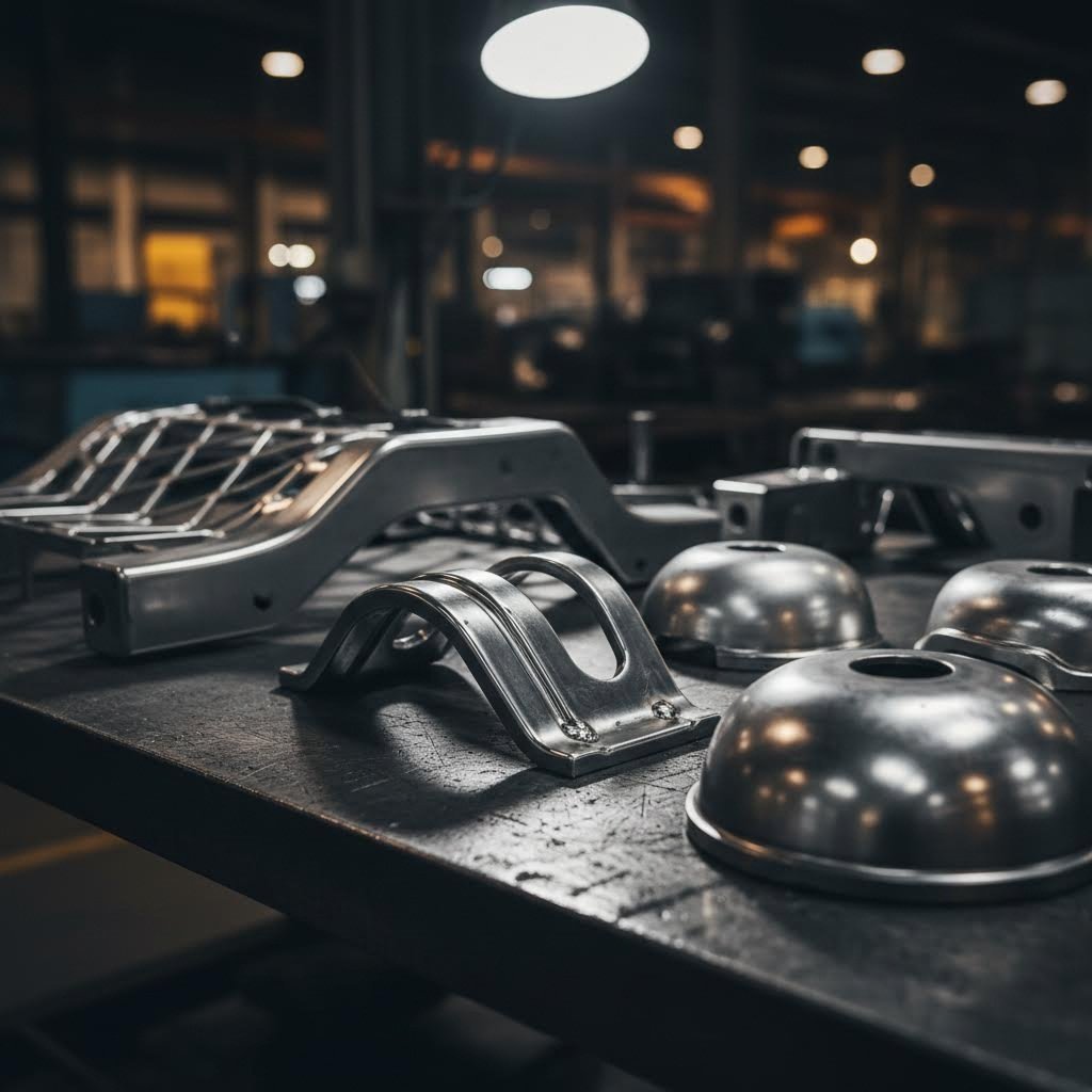
Unlike progressive die and stamping methods that excel with simpler geometries, transfer die operations dominate when parts demand complex three-dimensional shaping, deep draws, or operations on multiple surfaces. Let's explore where this capability translates into tangible manufacturing advantages.
Automotive Sector Applications and Requirements
Walk through any modern vehicle assembly plant, and you'll find transfer die components everywhere. The automotive industry represents the largest consumer of this technology—and for good reason. Progressive stamped automotive parts work perfectly for brackets and clips, but structural components demand the flexibility only transfer dies can provide.
According to Keysight's manufacturing analysis, transfer presses excel at "producing complex parts, such as automotive body panels, that require multiple operations during manufacturing." This capability makes them indispensable for:
- Structural brackets and reinforcements: These load-bearing components often require forming from multiple angles to achieve strength-optimizing geometries that progressive dies simply cannot access
- Seat frames and adjustment mechanisms: Complex curved profiles with integrated mounting features demand the multi-directional forming capability that automotive components progressive stamping via transfer dies enables
- Suspension components: Control arms, spring seats, and mounting brackets frequently require deep draws exceeding strip-attached limitations
- Body-in-white structural members: Floor pans, cross members, and reinforcement channels with complex contours and integrated attachment points
- Fuel system components: Tanks, housings, and mounting systems requiring leak-proof seams and multi-surface operations
Why does automotive favor this approach? Consider a typical seat frame. It requires deep-drawn sections for strength, pierced holes on multiple surfaces for mounting hardware, and precise tolerances where components interface. Keeping such a part attached to a carrier strip throughout production would be geometrically impossible—the strip would restrict access to interior surfaces and limit draw depths.
OEM Standards and Certification Requirements
Automotive applications bring stringent quality demands that influence every aspect of transfer die operations. Original Equipment Manufacturers typically require:
- IATF 16949 certification: The automotive quality management standard that ensures consistent production processes and defect prevention
- PPAP documentation: Production Part Approval Process records demonstrating that tooling and processes consistently produce parts meeting specifications
- Statistical process control: Ongoing monitoring of critical dimensions to verify process stability
- Material traceability: Complete documentation linking each part to specific material lots for recall capability
These requirements mean automotive transfer die operations must maintain exceptional consistency across millions of parts—a challenge that proper die design and maintenance directly addresses.
Medical and Industrial Transfer Die Applications
Beyond automotive, transfer die stamping serves critical roles in sectors where precision and reliability aren't just preferences—they're requirements.
Medical Device Manufacturing
Medical applications demand extreme precision combined with material biocompatibility. Transfer dies produce:
- Surgical instrument housings: Complex ergonomic shapes requiring operations on interior and exterior surfaces
- Implantable device enclosures: Titanium and stainless steel components with exacting dimensional requirements
- Diagnostic equipment chassis: Precision-formed frames providing electromagnetic shielding and structural support
- Sterilization containers: Deep-drawn stainless steel vessels with integrated sealing surfaces
The electrical stamping process for medical electronics often requires the same transfer die flexibility—enabling complex shielding geometries and connector housings that progressive methods cannot achieve.
Electrical and Electronics Enclosures
Protection of sensitive electronics demands precision-formed housings with tight tolerances:
- Control panel enclosures: Deep-drawn boxes with integrated mounting bosses and cable management features
- Junction boxes: Weather-resistant housings requiring operations on all six sides
- Transformer cases: Large enclosures with complex internal mounting provisions
- Heat sink housings: Aluminum enclosures with integrated fins requiring multi-angle forming
Industrial Equipment Components
Heavy equipment and industrial machinery rely on transfer-formed components for durability and precision:
- Hydraulic reservoir components: Deep-drawn tanks and covers with integrated fittings
- Pump housings: Complex geometries directing fluid flow while containing pressure
- Agricultural equipment panels: Large structural components with multiple mounting and access provisions
- HVAC system components: Blower housings, ducting connections, and damper assemblies
As noted by press technology experts, transfer systems "perform various operations, such as forming, piercing, and trimming, in a single setup, ensuring high efficiency and minimizing handling time." This efficiency proves particularly valuable in industrial applications where component complexity would otherwise require multiple discrete operations.
Whether you're manufacturing safety-critical automotive structures or precision medical housings, the key is matching your specific requirements to the right process. Understanding when transfer die capability becomes essential—rather than optional—helps you make decisions that optimize both quality and cost.
When to Choose Transfer Die Stamping
You understand the process, the design requirements, and the material options. Now comes the decision that actually matters: should you invest in transfer die stamping for your specific project? The answer isn't always obvious—and getting it wrong means either overspending on capability you don't need or struggling with a process that can't deliver what your parts require.
This decision framework cuts through the complexity. By systematically evaluating your requirements against each die type's strengths, you'll identify the right approach before committing tooling dollars.
Volume and Complexity Decision Factors
The intersection of production volume and part complexity creates a decision matrix that guides most die stamping choices. According to Larson Tool & Stamping's comprehensive guide, volume thresholds significantly influence which tooling approach makes economic sense.
Here's how volume requirements typically align with die type selection:
- Low volume (under 10,000 parts): Transfer dies may be difficult to justify economically unless part complexity absolutely demands it. Soft tooling or manual transfer operations might prove more cost-effective for prototype runs and limited production.
- Mid volume (10,000-100,000 parts): This range often represents the sweet spot for transfer die investment. The per-part tooling cost becomes reasonable, and complex geometries benefit from dedicated transfer tooling that eliminates secondary operations.
- High volume (100,000+ parts): Both progressive and transfer dies become economically viable—the decision shifts entirely to capability. If the progressive stamping process can produce your part, it typically offers lower per-piece costs. If geometry demands free-state operations, transfer stamping delivers despite higher operational complexity.
But volume alone doesn't tell the complete story. Part characteristics often override volume considerations entirely. As KenMode's analysis explains, transfer die stamping becomes the preferred—or only—option when parts require:
- Large blank sizes: Parts too large to efficiently progress through strip-fed tooling
- Deep draws exceeding strip limitations: When draw depth would tear the carrier strip or restrict forming access
- Operations on multiple part surfaces: Threading, chamfering, or forming on both sides of the workpiece
- Tube or shell configurations: Enclosed geometries that cannot remain strip-attached
- Frames or structural components: Complex perimeter shapes requiring access from various angles
Understanding the purpose of bypass notches in stamping dies illustrates why geometry matters so much. These notches allow carrier strips to flex during progressive operations—but they also limit how aggressively you can form parts. When your design exceeds these inherent progressive die constraints, transfer stamping becomes necessary regardless of volume.
Cost-Benefit Analysis for Die Selection
The economics of pressing and stamping decisions extend far beyond initial tooling investment. A complete cost-benefit analysis must consider the entire production lifecycle.
Tooling Investment Comparison
Progressive die metal stamping typically demands higher upfront tooling costs because all operations integrate into a single complex die. Transfer dies, while individually less complex per station, require investment in both tooling and transfer mechanisms. Here's the practical breakdown:
| Cost Factor | Progressive Die | Transfer Die |
|---|---|---|
| Initial Tooling Investment | $50,000 - $500,000+ | $40,000 - $300,000+ |
| Transfer System Cost | Not required | $20,000 - $100,000+ (if not existing) |
| Design Engineering Hours | Higher (integrated complexity) | Moderate (independent stations) |
| Modification Flexibility | Limited—changes affect entire die | Higher—stations can be modified independently |
| Typical Amortization Period | 500,000 - 2,000,000 parts | 100,000 - 1,000,000 parts |
Per-Part Cost Dynamics
At different volume levels, per-part economics shift dramatically:
- At 25,000 parts: Tooling costs dominate. Transfer dies may show lower total cost if they enable simpler station designs.
- At 100,000 parts: Operational efficiency becomes more significant. Progressive dies' higher speed (often 3-5x faster cycle times) starts delivering meaningful cost advantages for geometrically compatible parts.
- At 500,000+ parts: Per-piece cost differences between methods narrow, but cumulative savings from progressive die speed can reach significant totals. However, secondary operation elimination with transfer dies can offset this advantage.
Secondary Operation Elimination
Here's where transfer die stamping often wins the economic argument despite higher cycle times. Consider what happens when a part requires:
- Tapping or threading operations
- Welding of brackets or components
- Forming on surfaces inaccessible in progressive tooling
- Insertion of hardware or secondary components
Each secondary operation adds handling, equipment, labor, and quality control costs. Transfer dies frequently incorporate these operations directly—eliminating separate workstations and the associated overhead. A part requiring three secondary operations after progressive stamping might cost less per piece when produced complete in a transfer die, despite the slower primary cycle time.
Total Cost of Ownership Considerations
Beyond direct production costs, evaluate:
- Inventory and work-in-process: Parts requiring secondary operations sit in queue between stations, tying up capital and floor space
- Quality risk: Each handling operation introduces defect opportunities. Integrated transfer die production reduces touch points
- Flexibility value: Transfer die stations can be reconfigured for engineering changes more readily than integrated progressive dies
- Scrap rates: Transfer dies often achieve lower scrap rates on complex parts because each station can be optimized independently
The decision ultimately comes down to matching process capability to part requirements while optimizing total delivered cost. Simple geometry at high volume? Progressive die stamping almost always wins. Complex three-dimensional parts requiring multi-surface operations? Transfer die capability delivers value that justifies the investment.
Once you've selected the right approach, maintaining that tooling properly becomes essential for realizing the economic benefits you've projected.
Maintenance and Operational Excellence
You've invested significantly in transfer die tooling—now how do you protect that investment and keep it performing at peak efficiency for years to come? Unlike progressive stamping dies that operate in a relatively contained environment, transfer die systems involve multiple moving components that demand coordinated maintenance attention.
The reality is that maintenance requirements for transfer die operations often go undocumented in competitor resources, leaving manufacturers to learn expensive lessons through trial and error. Let's change that by covering the complete maintenance lifecycle—from daily inspections to major component overhauls.
Preventive Maintenance Best Practices
Effective maintenance starts before problems appear. A structured preventive program extends tool life, maintains part quality, and prevents the catastrophic failures that shut down production lines. Here's what a comprehensive inspection and maintenance schedule looks like:
Daily Inspection Checkpoints
- Transfer finger condition: Check for wear, damage, or misalignment that could cause misfeeds or part damage
- Lubrication levels: Verify automatic lubrication systems are functioning and reservoirs are adequately filled
- Part quality sampling: Measure critical dimensions on first-off and periodic parts to detect gradual drift
- Scrap and slug ejection: Confirm all waste material is clearing properly to prevent die damage
- Sensor functionality: Test part-present sensors and misfire detection systems
Weekly Maintenance Tasks
- Die surface inspection: Examine punch faces and die buttons for wear patterns, galling, or chipping
- Transfer rail alignment: Verify rails remain parallel and properly spaced throughout the stroke
- Gripper pressure verification: Check that pneumatic or mechanical grippers maintain consistent clamping force
- Timing verification: Confirm transfer motion synchronizes properly with press stroke
- Fastener torque checks: Verify critical bolted connections remain tight
Monthly Deep Inspections
- Punch and die measurement: Compare critical tool dimensions against original specifications to quantify wear
- Spring condition assessment: Check stripper springs and other spring-loaded components for fatigue
- Wear plate evaluation: Measure guide wear plates and replace before excessive clearance develops
- Transfer mechanism service: Inspect cam followers, bearings, and drive components for wear
- Electrical system review: Check sensors, wiring, and control connections for damage or degradation
Modern automatic stamping systems often incorporate condition monitoring that tracks punch forces, transfer timing, and other parameters in real-time. These systems can predict maintenance needs before failures occur—transforming reactive repairs into planned downtime.
Maximizing Transfer Die Service Life
How long should a transfer die last? The answer varies dramatically based on material being stamped, production volume, and maintenance quality. Well-maintained progressive stamping dies running mild steel might produce millions of parts before major refurbishment. Transfer dies face similar lifespans when properly cared for, but their multi-component nature creates more potential failure points.
Sharpening Intervals and Procedures
Cutting edges gradually dull through normal operation. Key indicators that sharpening is needed include:
- Increased burr height on cut edges
- Rising punch force readings (if monitored)
- Visible edge rollover or chipping under magnification
- Inconsistent blank dimensions
Typical sharpening intervals range from 50,000 to 500,000 hits depending on material hardness and tool steel grade. Each sharpening removes 0.002" to 0.005" of material—meaning tools have a finite number of sharpening cycles before replacement becomes necessary. Tracking cumulative sharpening removes helps predict replacement timing.
Component Replacement Timing
Beyond cutting edges, other components require periodic replacement:
| Component | Typical Service Life | Replacement Indicators |
|---|---|---|
| Punches and Die Buttons | 500,000 - 2,000,000 hits | Excessive wear; cannot resharpen further |
| Stripper Springs | 1,000,000 - 5,000,000 cycles | Lost tension; inconsistent stripping |
| Guide Pins and Bushings | 2,000,000 - 10,000,000 cycles | Excessive clearance; visible wear |
| Transfer Fingers | 500,000 - 2,000,000 transfers | Grip surface wear; part marking |
| Cam Followers | 5,000,000 - 20,000,000 cycles | Noise; rough rotation; visible flat spots |
Setup Time and Changeover Considerations
For facilities running multiple products, die transfer and changeover efficiency directly impacts productivity. Transferring tooling between jobs requires careful attention to:
- Die height verification: Confirm shut height matches press settings before clamping
- Transfer finger adjustment: Reconfigure gripper positions and timing for new part geometry
- Feed system setup: Adjust coil width guides, straightener settings, and feed progression
- Sensor positioning: Relocate part-detect sensors to match new blank locations
- First-article verification: Run samples and verify all dimensions before production release
Quick die change systems can reduce changeover from hours to minutes—but only when standardized die mounting, utility connections, and transfer interfaces are designed into the tooling from the start.
Common Challenges and Troubleshooting Approaches
Even well-maintained transfer dies encounter operational issues. Knowing how to quickly diagnose and resolve problems minimizes downtime and prevents secondary damage.
Misfeed Troubleshooting
When parts fail to transfer correctly, check these potential causes:
- Gripper wear: Worn grip surfaces may not securely hold parts during acceleration
- Timing drift: Transfer motion may have drifted out of sync with press stroke
- Part lifter malfunction: Lifters may not be raising parts high enough for gripper engagement
- Lubrication excess: Too much lubricant can make parts slippery and difficult to grip
- Material variation: Incoming coil properties outside specification can affect blank dimensions and behavior
Part Quality Variations
When dimensions drift or surface quality degrades:
- Check tool wear: Measure punch and die dimensions against specifications
- Verify material properties: Confirm incoming coil matches specification for thickness and hardness
- Inspect alignment: Die misalignment causes uneven wear and dimensional inconsistency
- Evaluate lubrication: Insufficient or incorrect lubricant causes galling and surface defects
- Review press condition: Worn press gibs or connections introduce variability
Timing and Synchronization Issues
Transfer systems depend on precise timing coordination. When synchronization fails:
- Verify encoder signals: Confirm press position feedback is accurate
- Check mechanical linkages: Worn cams or linkages alter motion profiles
- Review servo parameters: Servo-driven systems may need position loop tuning
- Inspect clutch/brake: Mechanical press timing issues often trace to clutch or brake wear
The Role of Advanced Simulation in Maintenance Planning
Here's where modern engineering capabilities transform maintenance from reactive to predictive. Advanced CAE simulation during the die design phase can predict wear patterns before a single part is stamped. By modeling material flow, contact pressures, and stress concentrations, engineers identify high-wear zones and design appropriate wear compensation or material upgrades from the start.
This simulation-driven approach reduces costly die modifications during tryout and production. Manufacturers working with engineering partners who achieve high first-pass approval rates—some reaching 93% or better—benefit from tooling that performs as designed from day one. Fewer modifications mean lower lifecycle costs and faster time to stable production.
For facilities seeking precision stamping die solutions with this level of engineering sophistication, IATF 16949 certification ensures quality systems meet the demanding standards that OEM customers require. This certification encompasses not just initial die quality but ongoing process controls that maintain consistency throughout the tooling lifecycle.
When properly designed and maintained, your progressive stamping press and transfer die investments deliver reliable production for years. The key lies in establishing systematic maintenance practices from the start—then continuously refining them based on operational experience with your specific applications.
Getting Started with Transfer Die Stamping
You've now explored the complete landscape of transfer die stamping—from fundamental mechanics through design considerations, material selection, industry applications, decision frameworks, and maintenance practices. But knowledge without action doesn't produce parts. Let's translate everything you've learned into a practical roadmap for your next project.
Whether you're evaluating transfer stamping for the first time or considering it as an alternative to your current progressive die press operations, these final insights will help you move forward with confidence.
Key Takeaways for Your Stamping Project
Before engaging any die manufacturer, internalize these critical decision factors that determine project success:
Transfer die stamping becomes essential—not optional—when your part requires deep draws exceeding strip limitations, operations on multiple surfaces, or complex 3D geometries that cannot remain attached to a carrier strip during forming.
Remember the complete lifecycle considerations that affect your total cost of ownership:
- Design phase: Station spacing, gripper engagement points, and material orientation decisions made now determine production efficiency for years to come
- Material selection: Match material properties to forming requirements—springback characteristics, work hardening behavior, and surface finish needs all influence station design
- Tooling investment: Balance initial costs against secondary operation elimination. A prog die might cost less upfront, but integrated transfer operations often deliver lower total per-part costs
- Production planning: Transfer dies typically run 20-60 strokes per minute versus progressive speeds exceeding 1,500 for small parts—plan capacity accordingly
- Maintenance infrastructure: Establish preventive maintenance protocols before production starts, not after problems appear
Next Steps in Transfer Die Implementation
Ready to move forward? Here's what to prepare before contacting potential dies and stamping partners:
Specifications to Gather
- Complete part drawings with GD&T callouts for all critical dimensions
- Material specifications including grade, temper, and thickness tolerance requirements
- Annual volume projections and anticipated program life
- Surface finish requirements and any cosmetic surface designations
- Secondary operations currently planned (threading, welding, assembly) that might integrate into primary stamping
- Quality certification requirements (IATF 16949, ISO 9001, industry-specific standards)
Questions to Ask Potential Die Manufacturers
- What is your first-pass approval rate on transfer die projects of similar complexity?
- Do you use CAE simulation to validate forming operations before cutting steel?
- What is your typical timeline from design approval to first article samples?
- How do you handle engineering changes after tooling is built?
- What maintenance documentation and training do you provide with completed tooling?
- Can you demonstrate experience with my specific material and industry requirements?
The answers to these questions reveal whether a potential partner has the engineering depth your project demands. A die stamping machine is only as good as the tooling running in it—and that tooling reflects the expertise of its designers.
Finding the Right Manufacturing Partner
For projects requiring precision and reliability, partnering with manufacturers who combine advanced engineering capabilities with proven quality systems makes all the difference. Look for partners offering rapid prototyping capabilities—some can deliver initial samples in as little as 5 days—along with comprehensive mold design and fabrication services under one roof.
Advanced CAE simulation capabilities prove particularly valuable for transfer die projects. Simulation-validated designs achieve higher first-pass approval rates (leading manufacturers reach 93% or better), reducing costly iterations and accelerating time to production. This engineering-first approach delivers defect-free results while keeping tooling costs competitive.
For manufacturers seeking cost-effective, high-quality tooling tailored to OEM standards, exploring partners with IATF 16949 certification ensures quality systems align with automotive industry requirements. Shaoyi's precision stamping die solutions exemplify this approach—combining rapid prototyping, advanced simulation, and certified quality systems to deliver transfer die tooling that performs from first article through millions of production parts.
Your next stamping project deserves tooling designed for success from the start. Armed with the knowledge from this guide, you're prepared to make informed decisions, ask the right questions, and partner with manufacturers who share your commitment to quality and efficiency.
Frequently Asked Questions About Transfer Die Stamping
1. What is the difference between a progressive die and a transfer die?
Progressive dies keep workpieces attached to a carrier strip throughout production, limiting access to only one side and restricting draw depth. Transfer dies separate blanks immediately after cutting, using mechanical grippers to move free-standing parts between independent stations. This fundamental difference enables transfer dies to perform deep draws, multi-surface operations, and complex 3D forming that progressive dies cannot achieve. Transfer dies typically run at 20-60 strokes per minute versus progressive speeds exceeding 1,500 for small parts, but they eliminate secondary operations that would otherwise be required.
2. What is a progressive die?
A progressive die is a metalworking tool that performs multiple stamping operations sequentially as a metal strip feeds through the press. Each station in the die completes a specific operation—punching, bending, coining, or forming—while the workpiece remains attached to the carrier strip. The strip advances with each press stroke until the final station separates the completed part. Progressive dies excel at high-speed production of simpler geometries, often reaching 1,500+ strokes per minute for small components like electrical contacts and brackets.
3. What is the difference between a progressive die and a compound die?
Progressive dies complete multiple operations sequentially across several stations in a single press stroke, with parts remaining on a carrier strip. Compound dies perform multiple operations simultaneously in a single stroke at one station, typically for simpler flat parts like washers. Transfer dies offer a third option, separating parts immediately and moving them freely between independent stations for complex 3D geometries. Compound dies have lower tooling costs but limited geometric capability, while progressive dies offer higher speeds for moderate complexity parts.
4. When should I choose transfer die stamping over progressive die stamping?
Choose transfer die stamping when your parts require deep draws exceeding strip limitations, operations on multiple surfaces, tubular or shell configurations, or complex 3D geometries that cannot remain attached to a carrier strip. Transfer dies also excel when integrating secondary operations like threading, welding, or hardware insertion directly into the stamping sequence. For medium to high production volumes of complex structural components—automotive seat frames, suspension parts, or medical device housings—transfer dies often deliver lower total per-part costs despite slower cycle times by eliminating separate secondary operations.
5. What materials work best with transfer die stamping?
Transfer die stamping handles a wide range of metals including low carbon steel (0.5-6.0mm), stainless steel (0.3-3.0mm), aluminum (0.5-4.0mm), brass (0.2-2.5mm), and copper (0.2-2.0mm). Low carbon steel offers excellent formability at low cost, making it ideal for automotive brackets and structural components. Stainless steel work hardens rapidly and requires higher tonnage but delivers corrosion resistance for medical and food equipment. Brass and copper provide outstanding drawability for electrical connectors and plumbing fixtures. Material selection affects press tonnage requirements, springback compensation needs, and die maintenance intervals.