 Small batches, high standards. Our rapid prototyping service makes validation faster and easier —

Die Roll Vs Burr Height: 5 Ranked Fixes For Edge Quality Control
Why Die Roll and Burr Height Demand Equal Attention
Picture this: you're standing at the inspection station, freshly stamped part in hand, running your finger along the cut edge. Something feels off. The burr catches your glove on one side, while the opposite edge shows that telltale rounded zone that signals excessive die roll. You know this part is heading for the reject bin—and worse, you're not entirely sure which parameter to adjust first without making the other problem worse.
Sound familiar? Every experienced tool and die maker has faced this exact moment. The frustrating reality is that most technical resources treat die roll vs burr height as separate issues, leaving engineers to figure out the critical connection on their own.
The Hidden Connection Most Engineers Miss
Here's what makes edge quality control so challenging: die roll and burr height aren't independent variables. They're deeply interconnected phenomena that respond to the same process parameters—often in opposite directions. When you tighten clearance to reduce burr formation, you're simultaneously increasing the yielding force that creates die roll. It's a delicate balancing act that requires understanding both characteristics together.
Think of it like a seesaw. Push down on one end (burr reduction), and the other end (die roll) rises. The key is finding that equilibrium point where both remain within acceptable limits for your application.
Why Edge Quality Defines Part Performance
Edge quality isn't just about aesthetics—it directly impacts part functionality. Excessive burr height creates safety hazards, interferes with assembly operations, and can compromise spot welder welding quality in downstream processes. Meanwhile, excessive die roll affects dimensional accuracy and can cause fitment issues in precision applications where yield strength requirements are critical.
The tool and die industry has long understood these individual effects. What's been missing is a comprehensive framework for managing the trade-off between them.
Understanding the Die Roll-Burr Height Trade-Off
This guide delivers exactly that framework. We've ranked five proven approaches for controlling die roll vs burr height, evaluated against real-world effectiveness and implementation practicality. You'll discover how clearance adjustments create predictable shifts in both characteristics, why certain blade geometries favor one outcome over another, and when material properties make the difference between success and scrap.
Whether you're troubleshooting a sudden quality shift or designing a new stamping process from scratch, this resource provides the decision frameworks you need to balance both edge characteristics based on your specific application requirements.
Our Methodology for Ranking Edge Quality Solutions
Before diving into specific solutions, you need to understand how we evaluated each approach. Not all fixes are created equal—some deliver excellent results but require significant investment, while others offer quick wins with limited scope. Our ranking system accounts for these trade-offs so you can make informed decisions based on your specific operation.
Five Critical Evaluation Factors for Edge Quality
We assessed each die roll vs burr height management approach against five core criteria drawn from established metalforming industry standards and decades of practical shop floor experience. Here's what we measured:
- Clearance Percentage Impact: How effectively does the approach allow you to fine-tune punch-to-die clearance for optimal edge characteristics? This factor evaluates the precision and range of control each method provides over the fundamental mechanical relationship.
- Material Compatibility: Does the solution work consistently across different steel grades, aluminum alloys, and advanced high-strength steels? Some approaches excel with specific materials but fall short when yield strength yield stress characteristics vary significantly.
- Measurement Reliability: Can you consistently measure and verify results? A solution is only as good as your ability to confirm it's working. We prioritized approaches that integrate well with established quality system and management protocols.
- Cost-Effectiveness: What's the total investment versus the return? This includes initial implementation costs, ongoing maintenance, training requirements, and potential productivity impacts.
- Production Speed Considerations: Does implementing this approach slow down your operation? We evaluated cycle time impacts, setup requirements, and flexibility during production runs.
How We Ranked Each Approach
Our ranking methodology weighs both theoretical effectiveness and real-world implementation challenges. An approach that delivers perfect edge quality but requires two-week tool changeovers simply isn't practical for most operations. We balanced ideal outcomes against what actually works on the production floor.
Each solution received scores across all five criteria, then we weighted these scores based on typical manufacturing priorities. The final rankings reflect approaches that consistently deliver results across diverse applications—from automotive stamping to precision electronics components.
Material-Specific Considerations in Our Analysis
Different materials respond differently to the same process adjustments. A clearance setting that produces excellent results on mild steel might create excessive burr on hardened steel grades or unacceptable die roll on softer aluminum. Our evaluation accounts for these material-specific behaviors, noting when certain approaches work better for particular material families.
Keep in mind that your specific application may weight these factors differently. Aerospace manufacturers might prioritize measurement reliability above all else, while high-volume automotive operations may emphasize production speed. Use our rankings as a starting point, then adjust based on your industry requirements and quality specifications.
Precision Die Clearance Optimization Takes the Top Spot
When it comes to managing die roll vs burr height, nothing delivers more predictable, repeatable results than optimizing your punch-to-die clearance. This approach earns our top ranking because it addresses the fundamental mechanical relationship between these two edge characteristics—giving you direct control over the trade-off rather than working around it.
Understanding why clearance optimization works so effectively requires grasping a simple principle: the gap between your punch and die determines how material separates during cutting. Get this gap right, and you've solved most of your edge quality challenges before they start.
The Clearance Sweet Spot for Your Material
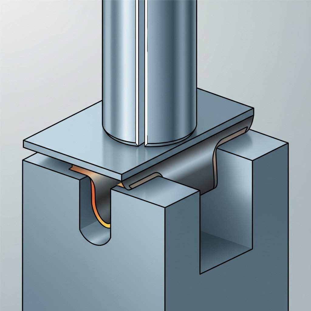
Here's the core relationship you need to understand: clearance and edge quality follow an inverse pattern. When you tighten clearances (reduce the punch-to-die gap), burr height decreases because material shears more cleanly with less plastic deformation at the cut edge. However, that same tighter clearance increases die roll because material experiences more bending stress as it flows into the die cavity before separation occurs.
Conversely, looser clearances reduce die roll by allowing material to separate earlier in the stroke cycle—but this creates larger burrs as more material tears rather than shears cleanly. The sweet spot exists where both characteristics remain within your acceptable tolerance window.
What makes this tricky is that the sweet spot shifts based on material properties. The elastic modulus and yield stress and yield strength characteristics of your workpiece directly influence where optimal clearance falls. A material with high modulus of elasticity of steel values responds differently than softer aluminum alloys with lower elastic modulus of steel properties.
How Punch-to-Die Gap Controls Both Phenomena
Imagine the cutting process in slow motion. As your punch descends, it first contacts the material and begins pushing downward. Before any cutting occurs, the material bends—this bending creates die roll on the punch side of your part. The amount of bending before fracture depends heavily on clearance percentage.
With tighter clearances, the punch must push material further into the die cavity before separation initiates. This extended bending phase produces more pronounced die roll. However, when fracture finally occurs, the shear zone is narrower and cleaner, resulting in minimal burr formation.
With looser clearances, separation initiates earlier because the unsupported span allows material to fracture sooner. Less bending means reduced die roll—but the fracture zone becomes rougher, and more material tears rather than shears cleanly. This torn material creates your burr.
Material thickness compounds these effects significantly. Thicker materials require proportionally larger clearances to achieve similar edge quality. A clearance percentage that works perfectly on 1mm stock will likely produce excessive burr on 3mm material of the same grade.
Clearance Percentage Guidelines by Material Type
The following table provides starting-point clearance recommendations based on material type. These percentages represent clearance per side as a percentage of material thickness—the industry-standard way to express this critical parameter.
| Material Type | Recommended Clearance (% of Thickness) | Expected Die Roll | Expected Burr Height | Key Considerations |
|---|---|---|---|---|
| Mild Steel (CR/HR) | 6-10% | Moderate | Low to Moderate | Good balance at 8%; adjust based on specific grade |
| Advanced High-Strength Steel (AHSS) | 10-14% | Low to Moderate | Moderate | Higher clearance reduces tool wear; watch for edge cracking |
| Aluminum Alloys | 8-12% | Moderate to High | Low | Softer alloys need tighter clearance; watch for galling |
| Stainless Steel (300/400 Series) | 8-12% | Moderate | Moderate to High | Work hardening affects results; consider coated tooling |
These recommendations serve as starting points. Your specific application may require adjustment based on part geometry, tolerance requirements, and downstream processing needs. The modulus of steel for your specific grade affects material springback and separation behavior—consult your material supplier's data sheets for precise mechanical property values.
Finding Optimal Settings Before First Parts
The traditional approach to clearance optimization involved cutting test parts, measuring results, adjusting tooling, and repeating until acceptable quality was achieved. This trial-and-error method works—but it's time-consuming and expensive, especially when working with costly materials or tight production schedules.
Modern CAE simulation changes this equation dramatically. Advanced simulation tools can predict die roll vs burr height outcomes before cutting a single part, allowing engineers to optimize clearance settings virtually. This capability proves especially valuable when working with new materials or complex part geometries where historical experience doesn't directly apply.
Engineers using CAE simulation can model multiple clearance scenarios, evaluate stress distributions throughout the cutting cycle, and predict edge quality outcomes with remarkable accuracy. This reduces trial-and-error iterations from dozens to just a handful of validation runs. Precision stamping specialists with advanced simulation capabilities, like those offering IATF 16949-certified die solutions, can often predict optimal clearance settings during the design phase—accelerating time to production while improving first-pass quality rates.
Pros of Clearance Optimization
- Precise Control: Directly addresses the fundamental mechanical relationship, giving you predictable cause-and-effect adjustments
- Predictable Results: Once optimal settings are established, results remain consistent across production runs with stable materials
- Universal Applicability: Works across all material types, thicknesses, and part geometries—no material-specific limitations
- Simulation-Ready: Modern CAE tools can predict optimal clearance before production, reducing development time and scrap
Cons of Clearance Optimization
- Tooling Precision Required: Achieving specific clearances demands accurate die construction and maintenance—worn tooling shifts clearance unpredictably
- Material Batch Sensitivity: Variations in incoming material properties (thickness, hardness) may require clearance adjustments between batches
- Setup Complexity: Verifying actual clearance on the press requires measurement expertise and appropriate gauging equipment
- Limited In-Process Adjustment: Unlike speed settings, you can't adjust clearance during a production run without stopping the press
Despite these limitations, clearance optimization remains the most effective approach for managing the die roll vs burr height balance. It addresses root causes rather than symptoms, and the investment in proper tooling and measurement capabilities pays dividends across every part you produce. When combined with the approaches we'll cover next—cutting angle geometry and tool maintenance—clearance optimization forms the foundation of comprehensive edge quality control.
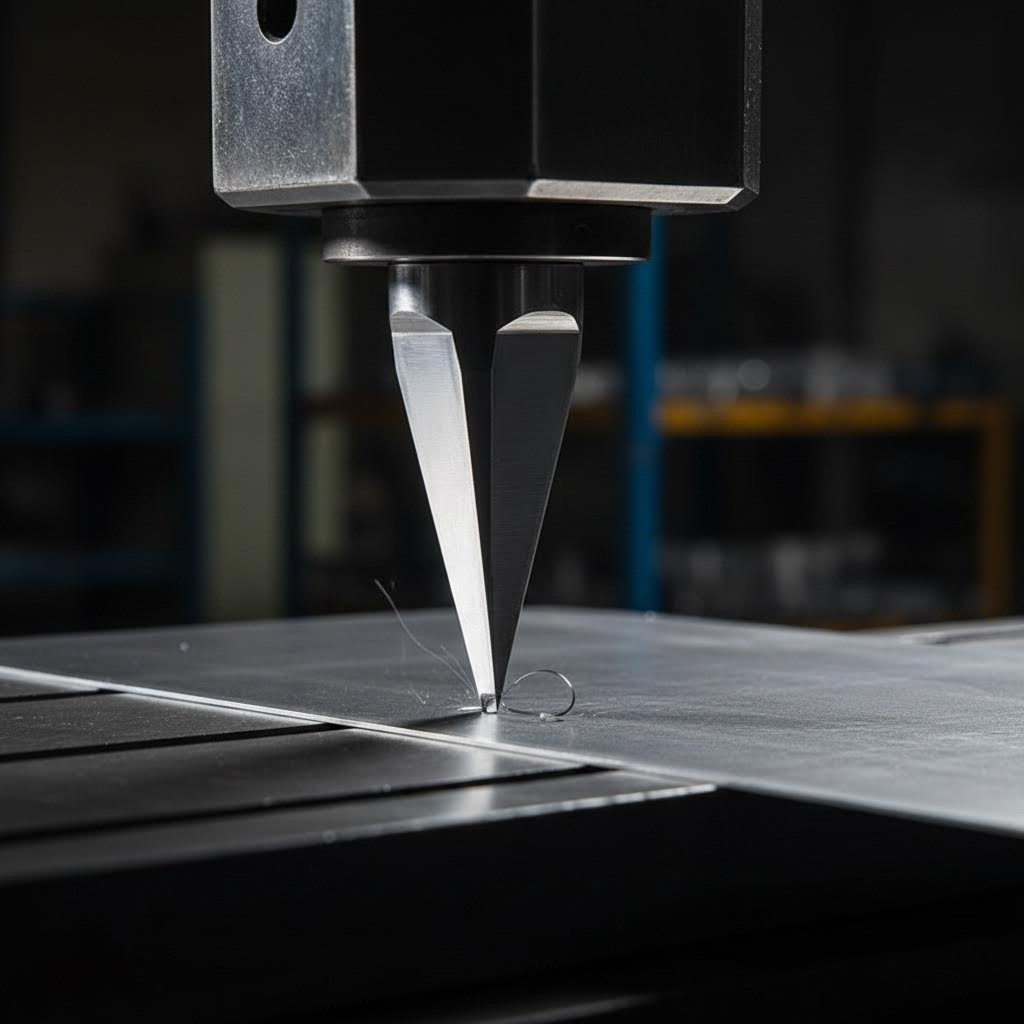
Cutting Angle Geometry Ranks Second for Edge Control
While clearance optimization gives you the most direct control over die roll vs burr height, cutting angle geometry earns a strong second place for a compelling reason: it fundamentally changes how stress distributes through your material during separation. Rather than adjusting the gap between punch and die, you're reshaping the cutting action itself—and that opens up possibilities that clearance adjustments alone can't achieve.
Think of the difference between cutting paper with scissors held flat versus angled. The angled approach requires less force and produces a cleaner cut. The same principle applies to metal stamping, though the engineering gets considerably more complex.
Blade Geometry Secrets for Cleaner Edges
Traditional flat cutting—where the punch face contacts material simultaneously across its entire perimeter—generates maximum cutting force at the moment of impact. This sudden load creates stress concentrations that contribute to both burr formation and die roll. The material experiences intense localized strain hardening at the cut edge, which affects how cleanly it separates.
Tapered cutting approaches distribute this force progressively across the cutting stroke. Instead of the entire perimeter engaging at once, contact begins at one point and sweeps across the material as the punch descends. This progressive engagement reduces peak forces by 30-50% in typical applications—and that force reduction directly impacts edge quality.
Here's why force matters: excessive cutting force accelerates work hardening at the shear zone boundary. When material work hardens too rapidly during cutting, it becomes more brittle at the edge, creating conditions that favor burr formation and irregular fracture patterns. By reducing peak forces through angular cutting, you allow material to separate more gradually with less aggressive strain hardening effects.
The geometry of your cutting edge also influences material flow patterns during separation. Sharp, well-designed angles guide material away from the cut zone more efficiently, reducing the tendency for torn edges that create burrs. Some operations have found success combining angular cutting with techniques borrowed from spin forming—using tool geometry to guide material flow rather than simply forcing separation.
Shear Angle Impact on Edge Quality
Shear angle refers to the angle at which your cutting edge meets the material—and different angles create dramatically different stress distributions that influence both die roll and burr formation. Understanding these relationships helps you specify tooling that delivers optimal edge quality for your specific application.
Low shear angles (typically 2-5 degrees) provide modest force reduction while maintaining relatively uniform edge characteristics around the part perimeter. This approach works well when you need consistent edge quality on all sides and can't tolerate variation between the leading and trailing edges of your cut.
Higher shear angles (6-12 degrees) deliver more substantial force reduction but create asymmetric cutting conditions. The leading edge of the cut—where contact initiates—experiences different stress patterns than the trailing edge where separation completes. This asymmetry can produce noticeable differences in die roll and burr height around the part perimeter.
The stress distribution differences are significant. At the leading edge, material begins bending and flowing before the trailing edge has even contacted the punch. This progressive action reduces die roll at the leading edge because material separates before bending reaches its maximum. However, the trailing edge may show increased die roll because it experiences the full cumulative deformation of the stroke.
For applications where edge quality consistency matters more than absolute quality levels, lower shear angles often prove preferable. When overall quality is paramount and some perimeter variation is acceptable, higher angles deliver better aggregate results.
When to Choose Angular vs Flat Cutting
Not every application benefits from angular cutting geometry. The decision depends on your specific part requirements, production volumes, and quality priorities. Here's how to evaluate whether this approach makes sense for your operation.
Angular cutting excels when you're working with thicker materials where cutting forces become problematic. The force reduction benefits increase with material thickness—a 3mm blank sees proportionally greater advantage from tapered cutting than a 0.5mm blank. If your current process struggles with tool wear, press tonnage limitations, or excessive noise and vibration, angular geometry may solve multiple problems simultaneously.
Flat cutting remains preferable when edge consistency around the entire perimeter is critical. Precision components requiring identical die roll vs burr height characteristics on all edges may perform better with simultaneous cutting, even if overall force levels are higher. Flat cutting also simplifies tooling design and reduces initial costs.
Material properties influence this decision significantly. Strain hardening characteristics vary between materials—advanced high-strength steels and stainless grades that work harden rapidly benefit more from the reduced forces of angular cutting. Softer materials like mild steel and some aluminum alloys show less dramatic improvement because their work hardening behavior is less aggressive.
Pros of Cutting Angle Optimization
- Reduced Cutting Force: Peak forces drop 30-50% with properly designed shear angles, reducing stress on tooling and presses
- Improved Edge Quality on Specific Materials: Materials prone to aggressive strain hardening show cleaner edges with progressive cutting action
- Extended Tool Life: Lower forces mean less wear on cutting edges, increasing intervals between sharpening or replacement
- Reduced Press Wear: Lower peak loads extend press bearing and frame life while reducing noise and vibration
Cons of Cutting Angle Optimization
- More Complex Tooling Design: Angular cutting surfaces require precise manufacturing and more sophisticated die engineering
- Material-Specific Optimization Required: The optimal shear angle varies by material type, thickness, and mechanical properties
- Higher Initial Tooling Cost: Complex geometry increases die construction costs, though this often pays back through improved tool life
- Asymmetric Edge Characteristics: Higher shear angles create measurable differences between leading and trailing cut edges
The best use cases for cutting angle geometry optimization involve high-volume production where edge quality is critical and initial tooling investment can be amortized across millions of parts. Automotive structural components, appliance panels, and precision brackets all benefit from this approach when production volumes justify the engineering investment.
For operations already using angular cutting, even small geometry refinements can yield meaningful improvements. Sometimes adjusting shear angle by just 2-3 degrees shifts the die roll vs burr height balance enough to bring previously marginal parts into specification. Combined with the clearance optimization covered in our top-ranked approach, blade geometry gives you a second powerful lever for dialing in edge quality—and when both are optimized together, results often exceed what either approach achieves alone.
Tool Sharpness Maintenance Earns Third Position
You've dialed in your clearance settings and optimized your cutting geometry—but here's what catches many operations off guard: those carefully calibrated parameters drift as your tools wear. Tool sharpness maintenance earns our third-ranked position because it's often the most overlooked factor in managing die roll vs burr height, yet it's also one of the most accessible fixes available to any stamping operation.
What makes tool wear particularly insidious is how it breaks the typical inverse relationship between die roll and burr height. While most process parameters push these characteristics in opposite directions, worn tooling degrades both simultaneously. Understanding this wear pattern—and establishing protocols to prevent it—keeps your edge quality consistent across entire production campaigns.
The Wear Pattern That Signals Trouble
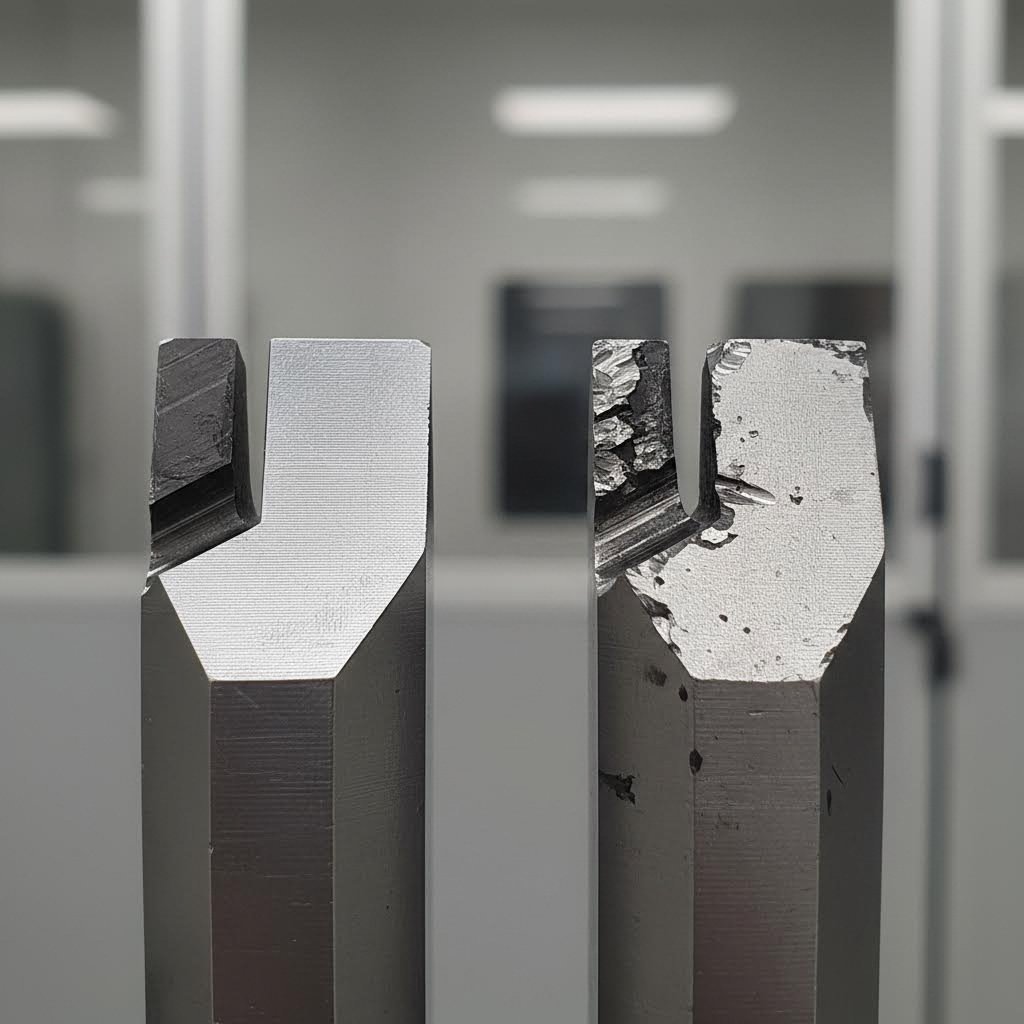
Fresh cutting edges produce clean, predictable separations. The sharp interface between punch and material creates a defined shear zone with minimal plastic deformation beyond the immediate cut area. But as cutting edges wear, this clean separation becomes increasingly compromised.
Worn punch edges don't cut—they push and tear. Instead of cleanly shearing material, a rounded cutting edge forces material to flow laterally before separation occurs. This lateral flow increases die roll on the punch side because material bends more extensively before fracture initiates. Simultaneously, the tearing action at separation creates larger, more irregular burrs on the die side.
Here's the critical insight: with sharp tooling, tightening clearance reduces burr but increases die roll (the inverse relationship). With worn tooling, both characteristics degrade together regardless of clearance settings. This breakdown of predictable cause-and-effect relationships is your signal that maintenance has become urgent.
The wear pattern itself tells a story. Examine your punch cutting edges under magnification. Fresh edges show a defined corner where the face meets the side wall. Worn edges display a visible radius—and that radius grows progressively with continued use. When this wear radius approaches or exceeds your material thickness, you've likely passed the yield point where acceptable edge quality becomes impossible.
Sharpening Intervals That Protect Edge Quality
Establishing effective sharpening schedules requires balancing production interruptions against quality degradation. Sharpen too frequently, and you're wasting capacity and accelerating tool consumption. Wait too long, and you're producing marginal or rejected parts while accelerating wear on other die components.
Material hardness provides your primary scheduling input. Harder materials—including advanced high-strength steels and work-hardened stainless grades—cause faster tool wear than softer materials like mild steel or aluminum. A punch that runs 500,000 hits on mild steel might need resharpening after just 50,000 hits on dual-phase AHSS.
Production volume determines whether you schedule sharpening by stroke count, calendar time, or quality metrics. High-volume operations benefit from stroke-count-based scheduling because wear accumulates predictably with each hit. Lower-volume operations might find calendar-based schedules more practical, with quality checks triggering early intervention when needed.
Consider these baseline sharpening intervals as starting points, then adjust based on your specific results:
- Mild Steel (under 40 HRB): 100,000-250,000 strokes depending on material thickness and part complexity
- High-Strength Steel (40-50 HRC): 30,000-80,000 strokes; higher hardness grades at lower end of range
- AHSS and Stainless: 15,000-50,000 strokes; these materials cause deformation hardening effects that accelerate wear
- Aluminum Alloys: 150,000-400,000 strokes; softer material is gentler on tooling but watch for galling buildup
Track your actual results to refine these intervals. The strain hardening and work hardening characteristics of your specific material grades affect wear rates significantly—two steels with identical hardness ratings but different alloy compositions can produce very different tool life outcomes.
Monitoring Tool Condition for Consistent Results
Effective monitoring catches degradation before it creates quality problems. Rather than waiting for rejected parts, proactive operations implement inspection protocols that identify wear trends and trigger maintenance at optimal timing.
Visual inspection remains your first line of defense. Operators trained to recognize wear patterns can often identify developing problems before they affect edge quality. Look for visible wear lands on cutting edges, chipping or micro-fractures, and buildup of work-hardened material on tool surfaces.
Measurement-based monitoring adds objectivity to your program. Edge quality metrics—burr height measurements, die roll depth readings, and edge roughness values—provide quantifiable data that tracks degradation over time. When measurements trend toward specification limits, you have advance warning to schedule maintenance.
Some operations implement cutting force monitoring as an early-warning system. As tools wear, cutting forces increase because more energy is required to push and tear material rather than cleanly shear it. Force sensors integrated into your press can detect these increases before edge quality visibly degrades, enabling truly predictive maintenance.
Pros of Tool Sharpness Maintenance
- Relatively Low Cost: Sharpening existing tooling costs a fraction of replacement, and maintenance equipment represents modest capital investment
- Immediate Impact: Freshly sharpened tools restore edge quality instantly—no trial-and-error optimization required
- Applicable to Existing Tooling: Works with your current dies and punches without requiring new tool designs or capital equipment
- Prevents Cascading Damage: Timely maintenance prevents worn punches from damaging die buttons and other components
Cons of Tool Sharpness Maintenance
- Requires Consistent Monitoring: Effective programs demand regular inspection and measurement—inconsistent attention leads to quality escapes
- Production Interruptions: Sharpening requires removing tools from service, creating scheduling challenges for high-volume operations
- Operator Skill Dependent: Both wear detection and sharpening quality depend on trained personnel with appropriate experience
- Limited by Tool Life: Every sharpening cycle removes material; eventually tools must be replaced regardless of maintenance quality
The key to successful tool maintenance lies in establishing clear protocols and following them consistently. Document your sharpening intervals, track actual versus planned maintenance, and correlate tool condition with edge quality metrics. Over time, this data allows you to optimize scheduling for your specific materials and production patterns—catching wear before it affects the die roll vs burr height balance while minimizing unnecessary production interruptions.
Material Selection Strategy Claims Fourth Rank
What if you could predict edge quality outcomes before cutting your first part—simply by knowing your material's mechanical properties? Material selection and preparation earns our fourth-ranked position because it addresses die roll vs burr height at the source. Rather than compensating for problematic edge behavior through process adjustments, this approach starts with materials whose inherent properties favor clean separation.
The challenge? You often don't get to choose your material. Customer specifications, cost constraints, and supply chain realities frequently dictate what shows up at your receiving dock. But when flexibility exists—or when you're troubleshooting persistent edge quality issues—understanding how material properties drive edge behavior becomes invaluable.
Material Properties That Predict Edge Behavior
Three mechanical properties dominate edge quality outcomes: yield stress, elongation, and work hardening rate. Understanding how each influences die roll and burr formation helps you anticipate problems before they appear on your parts.
Yield strength of steel determines how much stress material withstands before plastic deformation begins. Higher yield stress materials resist bending—which sounds beneficial for reducing die roll. However, these same materials often fracture more abruptly once deformation starts, creating irregular fracture zones that generate burrs. The relationship between tensile strength vs yield strength matters here: materials with a narrow gap between these values tend toward brittle separation with higher burr risk.
Elongation measures how much material stretches before fracturing. High-elongation materials flow and bend more readily, which typically increases die roll as material conforms to the die cavity before separation. However, that same ductility often produces cleaner fracture zones with reduced burr formation. Low-elongation materials resist bending (reducing die roll) but tend toward torn, irregular edges.
Work hardening rate describes how quickly material strengthens during plastic deformation. Rapid work hardening creates a narrow, highly stressed zone at the cut edge. When this zone becomes too brittle too quickly, irregular fracture patterns emerge—producing both increased die roll and larger burrs simultaneously.
The yield strain steel exhibits during cutting also affects results. Materials that achieve high strain before fracture initiation tend to show more pronounced die roll because bending continues longer before separation occurs. Matching your clearance settings to expected yield strain helps optimize the separation point.
AHSS Challenges and Solutions
Advanced high-strength steels present unique challenges that conventional approaches struggle to address. These materials—including dual-phase, TRIP, and martensitic grades—combine high strength with reasonable formability through sophisticated microstructures. But those same microstructures create unpredictable edge behavior.
The fundamental problem? AHSS grades often exhibit localized variations in hardness and ductility at the microstructural level. When your cutting edge encounters a hard martensitic region followed immediately by a softer ferritic zone, separation behavior changes mid-cut. This creates inconsistent die roll depths and irregular burr patterns that vary even within a single part.
Successful AHSS processing typically requires wider clearances than conventional steels—often 10-14% rather than the 6-10% range that works for mild steel. This increased clearance reduces cutting forces and allows more gradual separation, accommodating microstructural variations without creating extreme stress concentrations.
Edge cracking presents an additional AHSS concern. The low elongation of some advanced grades means that aggressive die roll can initiate cracks at the bent edge—cracks that propagate during subsequent forming operations or in-service loading. When working with AHSS, you may need to prioritize die roll reduction even at the expense of somewhat higher burr levels.
Material preparation matters more with AHSS than conventional steels. Incoming coil variations in thickness, hardness, and surface condition create larger edge quality swings. Implementing tighter receiving inspection and segregating material by lot helps maintain consistent processing results.
Aluminum vs Steel Edge Quality Differences
Switching from steel to aluminum—or vice versa—requires fundamental process adjustments because these materials separate through entirely different mechanisms. Understanding these differences prevents applying steel-based assumptions to aluminum processing.
Aluminum alloys typically exhibit lower yield stress and higher elongation than steel grades of comparable thickness. This combination produces more pronounced die roll as soft material flows readily into the die cavity. However, aluminum's ductility generally produces cleaner fracture zones with minimal burr—the opposite trade-off from high-strength steel.
The modulus of elasticity of aluminum runs roughly one-third that of steel. This lower stiffness means aluminum bends more readily under the same applied force, which directly increases die roll depth. Compensating through tighter clearances helps—but push too tight, and galling becomes problematic as aluminum adheres to tool surfaces.
Work hardening behavior differs significantly between these material families. Aluminum work hardens less aggressively than steel, meaning the cut edge remains more ductile. This reduces burr formation but can create long, stringy chips that wrap around punches and create handling problems.
Material thickness compounds these differences. Thick aluminum sections show disproportionately more die roll than equivalent steel thicknesses because the lower modulus allows more bending before separation forces build sufficiently to initiate fracture. When processing aluminum above 3mm thickness, expect die roll values 50-100% higher than comparable steel—and plan your tolerances accordingly.
Pros of Material Selection Strategy
- Addresses Root Cause: Rather than compensating for problematic material behavior, you start with properties that favor clean separation
- Predictable Outcomes: When incoming material is consistent, edge quality results repeat reliably across production runs
- Enables Process Standardization: Consistent material properties allow you to lock in optimal clearance, speed, and geometry settings
- Reduces Troubleshooting: Eliminating material variation as a variable simplifies root cause analysis when quality issues arise
Cons of Material Selection Strategy
- Limited Flexibility: Customer specifications, industry standards, and functional requirements often dictate material choice regardless of edge quality considerations
- Cost Implications: Materials with optimal edge quality characteristics may carry price premiums or require minimum order quantities
- Supply Chain Considerations: Specifying narrow material property ranges can limit supplier options and extend lead times
- Batch Variation: Even with tight specifications, heat-to-heat and coil-to-coil variations occur—requiring process flexibility despite material control efforts
This approach works best for applications where material specification flexibility exists and edge quality requirements justify the additional sourcing complexity. Precision components, safety-critical parts, and high-visibility applications often warrant the investment in material optimization. When you can't change your material, the insights from this analysis still help—understanding your material's inherent tendencies guides clearance selection, geometry choices, and realistic tolerance expectations for managing die roll vs burr height throughout production.
Press Speed Optimization Rounds Out the Top Five
Here's something many stamping operations overlook: you can adjust die roll vs burr height outcomes without touching your tooling at all. Press speed and stroke optimization earns our fifth-ranked position because it offers immediate, real-time control over edge quality—valuable for troubleshooting, fine-tuning, and prototype work where tooling modifications aren't practical.
Why does forming speed matter? Material doesn't respond instantly to applied force. The rate at which you apply yielding load influences how material flows, deforms, and ultimately separates during cutting. This strain-rate sensitivity creates an adjustment lever that exists entirely within your press controls.
Speed Settings That Minimize Edge Defects
When your punch descends faster, material experiences higher strain rates at the cutting zone. This rapid deformation changes material behavior in ways that directly affect edge quality. Understanding these effects helps you dial in speed settings that balance edge characteristics against productivity requirements.
At higher speeds, material has less time to flow plastically before separation initiates. This reduced flow time typically decreases die roll because bending doesn't progress as far before fracture occurs. However, the rapid separation can create more aggressive fracture patterns—sometimes increasing burr height as material tears rather than shears cleanly.
Slower speeds allow more gradual material flow. The extended deformation time gives material opportunity to redistribute stress, often producing cleaner fracture zones with reduced burr. But that same extended flow time means more bending before separation—potentially increasing die roll depth.
The relationship between speed and edge quality follows principles similar to yield in engineering mechanics. Just as materials exhibit different yield behavior under static versus dynamic loading, your cut edges respond differently to slow versus fast punch travel. Rate-sensitive materials—particularly certain aluminum alloys and some advanced high-strength steels—show more pronounced speed effects than rate-insensitive grades.
Stroke Optimization for Different Materials
Different materials respond to speed changes with varying intensity. Matching your stroke parameters to material characteristics maximizes the benefit you can extract from this adjustment approach.
Mild steel shows moderate speed sensitivity. You'll notice measurable edge quality differences across your available speed range, but the changes are gradual and predictable. This makes mild steel forgiving when dialing in optimal settings—small speed adjustments produce proportional edge quality shifts.
Aluminum alloys often exhibit stronger rate sensitivity. The formability limit diagram for many aluminum grades shifts noticeably with strain rate, meaning speed adjustments produce more dramatic edge quality changes. This sensitivity can work in your favor—or against you. Careful speed optimization often yields significant improvements, but process variation becomes more critical to control.
AHSS grades present mixed behavior. Some dual-phase and TRIP steels show pronounced rate sensitivity due to their complex microstructures, while martensitic grades respond more like conventional high-strength steel. When working with AHSS, start with conservative speed settings and adjust incrementally while monitoring edge quality carefully.
Material thickness influences optimal speed selection. Thicker materials generally benefit from slightly slower speeds because the larger volume of deforming material needs more time to flow and redistribute stress. Thin materials often tolerate—and sometimes prefer—faster speeds because the small deformation zone reaches separation quickly regardless of flow time.
Finding Your Process Window
Your optimal speed setting exists within a process window bounded by quality requirements on one side and productivity demands on the other. Finding this window requires systematic testing rather than guesswork.
Start by establishing your current baseline. Run a sample at your standard production speed and carefully measure both die roll depth and burr height at multiple locations around the part perimeter. Document these values as your reference point.
Next, run samples at speeds 20% slower and 20% faster than baseline—while holding all other parameters constant. Measure edge quality for each condition. This quick test reveals which direction offers improvement potential and whether your material is rate-sensitive enough to pursue further optimization.
If initial testing shows promise, narrow your investigation to the promising speed range. Test at smaller increments—perhaps 5% or 10% steps—to locate the optimal setting. Remember that you're looking for the best balance between die roll and burr height, not the absolute minimum of either characteristic.
Production realities constrain your options. The theoretically optimal speed might reduce cycle time below acceptable levels or create other process problems. Your final setting balances edge quality improvement against throughput requirements, part handling considerations, and equipment capabilities.
Pros of Press Speed Optimization
- No Tooling Changes Required: Adjust edge quality outcomes without removing dies from the press or modifying tool geometry
- Adjustable in Real-Time: Make changes during production runs to respond to material variation or quality drift
- Good for Troubleshooting: Quickly test whether speed is contributing to edge quality problems before investigating other causes
- Zero Additional Cost: Uses existing press capabilities without purchasing new equipment or tooling
- Reversible: If changes don't improve results, return to original settings instantly with no permanent consequences
Cons of Press Speed Optimization
- Productivity Trade-Offs: Slower speeds that improve edge quality reduce parts per hour, directly impacting production economics
- Limited Effectiveness Range: Speed adjustments typically produce smaller edge quality improvements than clearance or geometry changes
- Material-Dependent Results: Rate-insensitive materials show minimal response to speed changes, limiting applicability
- Equipment Constraints: Your press may not offer sufficient speed range to reach optimal settings for all applications
- Interaction Effects: Speed changes can affect other quality characteristics beyond edge quality, requiring comprehensive evaluation
The best use cases for speed optimization involve fine-tuning existing processes that are close to specification but need incremental improvement. When you're troubleshooting sudden quality changes—perhaps from a new material lot or seasonal temperature variation—speed adjustment offers quick diagnostic value. Prototype runs particularly benefit because you can explore the die roll vs burr height trade-off without committing to tooling modifications.
Speed optimization works best as a complementary approach rather than a primary solution. Combine it with properly optimized clearance settings and well-maintained tooling for comprehensive edge quality control—then use speed adjustments for final fine-tuning and real-time response to process variation.

Complete Comparison Matrix for All Five Approaches
Now that you've explored each approach individually, let's bring everything together in a unified reference that makes decision-making practical. Comparing die roll vs burr height solutions side-by-side reveals patterns that aren't obvious when examining each method in isolation—and these patterns guide smarter implementation strategies.
Whether you're selecting your first improvement initiative or building a comprehensive edge quality program, these comparison matrices help you match solutions to your specific operational context.
Side-by-Side Effectiveness Comparison
The following table consolidates our evaluation of all five ranked approaches across the key criteria that matter most for real-world implementation. Use this reference when weighing your options or presenting recommendations to stakeholders.
| Approach | Die Roll Reduction | Burr Height Reduction | Implementation Cost | Complexity | Best Application Scenarios |
|---|---|---|---|---|---|
| 1. Precision Die Clearance Optimization | High (adjustable via clearance percentage) | High (inverse relationship with die roll) | Medium (tooling precision required) | Medium | All materials and thicknesses; new die design; process standardization |
| 2. Cutting Angle Geometry | Medium-High (reduces bending forces) | Medium-High (cleaner separation) | High (specialized tooling) | High | High-volume production; thick materials; AHSS and stainless steel |
| 3. Tool Sharpness Maintenance | Medium (prevents degradation) | Medium (prevents degradation) | Low (maintenance vs. replacement) | Low-Medium | All operations; quick wins; existing tooling improvement |
| 4. Material Selection Strategy | Medium (material-dependent) | Medium (material-dependent) | Variable (sourcing implications) | Medium | New programs; specification flexibility; root cause elimination |
| 5. Press Speed Optimization | Low-Medium (rate-sensitive materials) | Low-Medium (rate-sensitive materials) | None (existing capabilities) | Low | Troubleshooting; fine-tuning; prototype runs; real-time adjustment |
Notice how the relationship between yield strength vs tensile strength in your material affects which approaches deliver the strongest results. Materials with narrow gaps between these values—typically harder, less ductile grades—respond better to clearance and geometry optimization, while softer materials with wider gaps often show more sensitivity to speed adjustments.
Understanding how to measure angles stamping during cutting provides insight into why geometry optimization ranks so highly. Precise angle measurement during tool design and verification ensures the force distribution benefits actually materialize in production.
Choosing the Right Approach for Your Application
Your optimal approach depends on several factors: current edge quality gaps, available resources, production volume, and how much flexibility you have in tooling and material specifications. Here's how to navigate these decisions.
If you're designing new tooling: Start with clearance optimization as your foundation. Specify clearances based on your material's yield stress of steel or aluminum properties, then layer in geometry optimization if volume justifies the investment. This combination addresses both phenomena from the start rather than fixing problems after they appear.
If you're troubleshooting existing processes: Begin with tool maintenance—it's the fastest, lowest-cost intervention. If fresh tooling doesn't resolve the issue, use speed optimization to diagnose whether strain-rate effects are contributing. These quick tests narrow your investigation before committing to more expensive solutions.
If you're working with challenging materials: AHSS and high-strength stainless grades demand the combined power of clearance optimization plus geometry refinement. The tensile modulus steel exhibits in these grades creates cutting conditions where single-approach solutions often fall short. Material selection becomes your third lever when specifications allow flexibility.
The steel modulus of elasticity for your specific grade influences how much die roll develops before separation—higher modulus materials resist bending, potentially reducing die roll but creating more abrupt separations. Factor this property into your clearance calculations and geometry decisions.
The most successful stamping operations rarely rely on a single edge quality approach. They combine optimized clearance settings with appropriate cutting geometry, maintain tooling rigorously, and use speed adjustments for fine-tuning—creating a layered system where each approach reinforces the others.
Industry-Specific Tolerance Requirements
Acceptable die roll and burr height limits vary dramatically by industry. What passes inspection for appliance panels might fail immediately in aerospace applications. The following table provides typical tolerance ranges—use these as benchmarks when establishing your own specifications.
| Industry | Acceptable Die Roll (% of thickness) | Acceptable Burr Height | Primary Concerns | Common Approach Combinations |
|---|---|---|---|---|
| Automotive Structural | 15-25% | ≤10% of thickness | Edge cracking in forming; weld quality | Clearance + Geometry + Maintenance |
| Automotive Visible/Class A | 10-15% | ≤5% of thickness | Surface appearance; assembly fit | Clearance + Geometry + Material |
| Aerospace | 5-10% | ≤0.05mm absolute | Fatigue life; stress concentrations | All five approaches; secondary operations |
| Electronics/Connectors | 8-12% | ≤0.03mm absolute | Dimensional precision; assembly interference | Clearance + Maintenance + Speed |
| Appliance Manufacturing | 20-30% | ≤15% of thickness | Handling safety; coating adhesion | Clearance + Maintenance |
Aerospace tolerances reflect the industry's focus on fatigue performance—even minor edge imperfections create stress concentrations that affect part life. Electronics applications prioritize dimensional consistency for assembly operations. Appliance manufacturing balances quality against high-volume economics, accepting wider tolerances where function allows.
Which Combinations Work Best Together
Not all approach combinations deliver equal value. Some pairings create synergy, while others address the same issues redundantly. Here's guidance on building effective multi-approach strategies:
- Clearance + Geometry: Excellent synergy. Optimized clearance establishes baseline separation behavior, while geometry refinement reduces forces and improves consistency. These approaches complement rather than overlap.
- Clearance + Maintenance: Essential pairing. Even perfect clearance specifications drift as tools wear. Maintenance preserves your calibrated settings across production campaigns.
- Geometry + Speed: Good for fine-tuning. Once geometry is optimized, speed adjustments provide real-time response to material variation without compromising the force-reduction benefits.
- Material + Clearance: Foundational combination. Material properties determine optimal clearance settings—these approaches work together naturally when both can be specified.
- All Five Together: Maximum control for demanding applications. Aerospace and precision electronics often justify comprehensive implementation where edge quality directly impacts part function or safety.
Building your edge quality strategy around these proven combinations—rather than pursuing each approach independently—creates a coherent system where improvements compound rather than conflict. With this comparison framework in hand, you're ready to develop specific action plans tailored to your current challenges.
Final Recommendations for Mastering Edge Quality
You've now explored five proven approaches for managing die roll vs burr height—each with distinct strengths, limitations, and optimal use cases. But knowing what works isn't the same as knowing what to do first. This final section transforms that knowledge into action, giving you a decision framework that matches solutions to your specific situation.
The truth? Most edge quality problems don't require implementing all five approaches simultaneously. Your current challenges point toward specific starting points. Let's identify yours.
Your Action Plan Based on Current Challenges
Different symptoms demand different responses. Before adjusting anything, diagnose what you're actually seeing on your parts. Then match your observation to the appropriate intervention:
- If you're seeing excessive burr with acceptable die roll: Start by tightening your clearance settings—reduce clearance by 1-2% increments while monitoring die roll. If burr persists, check tool sharpness; worn cutting edges create burr regardless of clearance. Consider whether your current material batch has different hardness than previous lots.
- If you're seeing excessive die roll with acceptable burr: Increase clearance slightly to allow earlier material separation. Evaluate cutting geometry—angular approaches reduce bending forces that create die roll. For materials with high Young's modulus of steel values, slightly faster press speeds may reduce flow time before fracture.
- If both die roll and burr height are problematic: Begin with tool maintenance. When both characteristics degrade simultaneously, worn tooling is your most likely culprit. Fresh cutting edges restore the predictable inverse relationship between these phenomena. Only after confirming sharp tooling should you pursue clearance optimization.
- If edge quality varies unpredictably within production runs: Investigate material consistency first. Batch-to-batch variations in yield point for steel or thickness tolerance create process instability that no amount of parameter adjustment can overcome. Tighten incoming inspection requirements.
- If quality is acceptable but margins are tight: Speed optimization offers fine-tuning capability without tooling changes. Small adjustments often shift results just enough to create comfortable specification margins.
Each die maker faces unique constraints—tooling already in production, customer-specified materials, equipment limitations. Your action plan must work within these realities while addressing root causes rather than symptoms.
When to Prioritize Die Roll vs Burr Height
Here's what separates experienced engineers from those still learning: recognizing that the optimal balance depends entirely on part function. There's no universal "correct" ratio—only the ratio that serves your specific application.
Prioritize die roll reduction when:
- Parts undergo subsequent forming operations where edge bending creates crack initiation sites
- Dimensional accuracy at the edge affects assembly fit or tolerance stack-up
- The cut edge becomes a sealing surface or functional interface
- Visual appearance matters and die roll creates noticeable shadows or irregularities
Prioritize burr height reduction when:
- Operators handle parts manually and burrs create safety hazards
- Downstream processes like hydroforming or welding require clean edge interfaces
- Parts mate with other components where burrs cause interference or damage
- Coating or plating operations follow stamping and burrs affect adhesion or coverage
Understanding what yield strength means for your application helps clarify priorities. High-strength applications often tolerate more burr if die roll stays controlled, while precision assemblies frequently accept moderate die roll to eliminate burr interference. Match your targets to function, not arbitrary numbers.
Building a Comprehensive Edge Quality Strategy
Sustainable edge quality control requires more than fixing today's problem—it demands a systematic approach that prevents tomorrow's issues. Building this strategy involves three layers: foundation, optimization, and continuous improvement.
Foundation layer: Establish proper clearance specifications during die design. Document your clearance standards by material type and thickness. Implement rigorous tool maintenance schedules based on production volume and material hardness. These fundamentals prevent the majority of edge quality problems before they occur.
Optimization layer: Once fundamentals are solid, pursue geometry optimization for high-volume or critical applications. Develop material specifications that favor edge quality when flexibility exists. Create process windows that balance quality against productivity.
Continuous improvement layer: Monitor edge quality metrics over time. Track trends that signal developing problems. Correlate quality data with process variables to identify improvement opportunities. Build institutional knowledge that transfers to new programs.
Validating your approach before committing to production tooling saves significant time and cost. Partnering with precision stamping specialists who offer rapid prototyping—some delivering prototype tooling in as little as 5 days—allows you to test edge quality outcomes before finalizing production die designs. This validation step proves especially valuable when working with new materials or challenging geometries where historical experience doesn't directly apply.
Engineering teams with advanced CAE simulation capabilities can predict die roll vs burr height outcomes during the design phase, often achieving first-pass approval rates exceeding 90% by optimizing clearance and geometry before cutting first parts. When selecting die design partners, prioritize those who understand this interconnected relationship and can deliver tooling tailored to your specific edge quality requirements.
For comprehensive mold design and fabrication capabilities backed by IATF 16949 certification, consider working with specialists who combine simulation expertise with high-volume manufacturing experience. This combination ensures your edge quality strategy translates from design intent to production reality.
Remember: mastering the die roll vs burr height balance isn't about achieving perfection on either characteristic. It's about understanding how they interact, predicting how process changes affect both, and matching your edge quality outcomes to what your parts actually require. With the frameworks and solutions outlined in this guide, you have the tools to make that happen consistently.
Frequently Asked Questions About Die Roll vs Burr Height
1. What is the acceptable burr height for stamped parts?
The industry standard for acceptable burr height is 10% of the sheet metal thickness, typically falling within 25-50 µm for precision applications. However, tolerances vary by industry—aerospace may require ≤0.05mm absolute, while appliance manufacturing accepts up to 15% of thickness. Automotive structural components generally follow the 10% rule, with visible Class A surfaces requiring tighter control at ≤5% of thickness.
2. How does die clearance affect burr height and die roll?
Die clearance creates an inverse relationship between burr height and die roll. Tighter clearances (smaller punch-to-die gaps) reduce burr formation because material shears more cleanly, but they increase die roll as material bends more before separation. Looser clearances reduce die roll by allowing earlier material separation but create larger burrs due to tearing rather than clean shearing. Optimal settings balance both characteristics based on material type and application requirements.
3. What causes burr height to increase during production runs?
Tool wear is the primary cause of increasing burr height during production. Fresh die clearances drift as tools wear—a die starting at 0.15mm clearance can reach 0.25mm after 100,000 hits, potentially doubling burr height. Worn punch edges don't cut cleanly; they push and tear material, creating larger burrs. Additionally, worn tooling breaks the typical inverse relationship between die roll and burr, degrading both characteristics simultaneously.
4. What clearance percentage should I use for AHSS stamping?
Advanced high-strength steels typically require 10-14% clearance per side, higher than the 6-10% used for mild steel. This increased clearance reduces cutting forces, accommodates microstructural variations in dual-phase and TRIP grades, and minimizes tool wear. AHSS exhibits localized hardness variations that create unpredictable edge behavior with tighter clearances. Watch for edge cracking, which may require prioritizing die roll reduction even at the expense of slightly higher burr levels.
5. How can I reduce both die roll and burr height simultaneously?
Start with tool maintenance since worn tooling degrades both characteristics together. Once tools are sharp, combine precision clearance optimization with cutting angle geometry—clearance establishes baseline separation behavior while angular cutting reduces forces and improves consistency. For challenging materials like AHSS, add material selection controls when specifications allow. Use press speed adjustments for fine-tuning. Partnering with die specialists offering CAE simulation can predict optimal settings before production, achieving 93%+ first-pass approval rates.