 Small batches, high standards. Our rapid prototyping service makes validation faster and easier —

Eliminating Burrs In Metal Stamping: From Hidden Costs To Clean Edges

Understanding Metal Burrs and Why They Matter in Stamping
Picture this: your stamping operation runs smoothly, parts come off the press looking perfect, and then quality control flags an entire batch for rejection. The culprit? Tiny metal burrs measuring less than a millimeter that somehow escaped detection. These seemingly insignificant imperfections cost manufacturers millions annually in scrap, rework, and customer returns. Understanding what burrs are and why they form is the first step toward eliminating them from your production process.
So, what are burrs exactly? In metal stamping, a metal burr refers to the unwanted raised edge, rough projection, or small piece of material that remains attached to a workpiece after stamping operations. Think of them as the ragged remnants left behind when metal is cut, punched, or sheared. They can appear as sharp protrusions along cut edges, rolled-over material on blank surfaces, or tiny attached fragments that refuse to separate cleanly from the parent material.
The Anatomy of Burr Formation in Stamping Operations
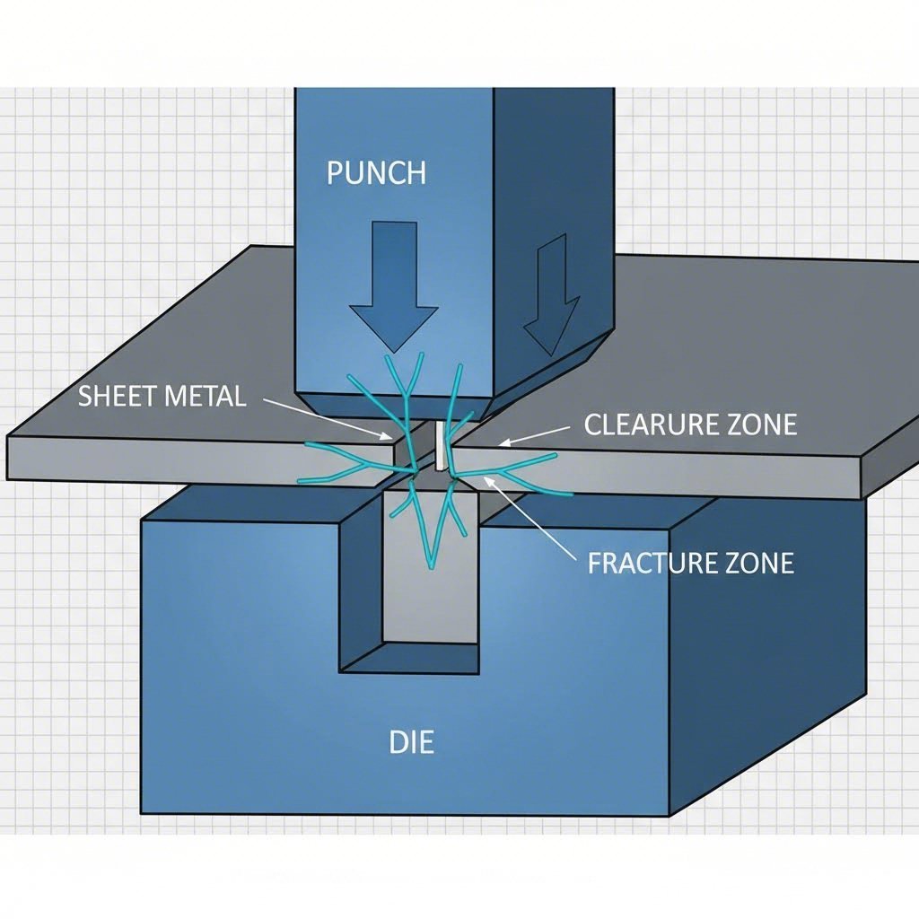
Understanding the meaning of deburring starts with grasping how metal burrs form in the first place. During the shearing and blanking process, the punch descends into the die, creating intense stress concentration at the cutting edges. The metal initially deforms elastically, then plastically, before finally fracturing along the shear zone.
Here's where things get interesting. The fracture doesn't occur instantaneously across the entire material thickness. Instead, the punch penetrates partially through the sheet metal before the remaining material tears away. This tearing action, combined with plastic flow of the metal, creates those characteristic raised edges we call burrs. The size and shape of metal burrs depend on several factors including die clearance, punch sharpness, material properties, and press speed.
When die clearance is too tight, the metal experiences excessive compression, leading to secondary shearing and larger burr formation. Conversely, excessive clearance allows the material to be drawn into the gap before fracturing, creating rolled-over burrs on the die side of the workpiece.
Why Even Microscopic Burrs Create Major Problems
You might wonder why such small imperfections demand so much attention. The reality is that burred metal causes cascading problems throughout manufacturing and end-use applications. Even microscopic burrs can derail product quality, compromise safety, and inflate production costs significantly.
The primary consequences of burrs in stamped parts include:
- Safety hazards: Sharp burr edges can cause cuts and lacerations to assembly workers handling parts. In consumer products, they pose injury risks to end users.
- Assembly interference: Parts with burrs may not fit properly into assemblies, causing binding, misalignment, or preventing complete seating of components.
- Coating adhesion issues: Paint, powder coating, and plating struggle to adhere uniformly over burr edges, leading to premature coating failure and corrosion.
- Aesthetic defects: Visible burrs diminish the perceived quality of finished products, potentially damaging brand reputation and customer satisfaction.
- Electrical and mechanical failures: In precision applications, burrs can cause short circuits, impede proper sealing, or create stress concentration points that lead to fatigue failure.
Beyond these direct impacts, the hidden costs multiply quickly. Downstream operations slow down when workers must handle parts carefully to avoid injury. Secondary deburring operations add labor, equipment, and cycle time costs. Customer complaints and returns erode profit margins while straining relationships with key accounts.
The good news? Once you understand the mechanics behind burr formation, you can implement targeted strategies to prevent them at the source or remove them efficiently when prevention isn't possible.
Diagnosing Burr Causes Through Systematic Analysis
When you encounter a burr in metal stamping, your first instinct might be to simply remove it and move on. However, treating burrs as isolated defects rather than symptoms of underlying process issues leads to recurring problems and mounting costs. The key to truly eliminating burrs lies in diagnosing their root causes through careful observation and systematic analysis.
Think of burrs as your stamping process trying to communicate with you. Every characteristic of a burr edge tells a story about what went wrong during the cutting operation. By learning to read these clues, you can identify the exact adjustments needed to prevent future occurrences rather than endlessly chasing symptoms.
Reading Burr Characteristics to Identify Root Causes
The location, size, direction, and appearance of burrs on metal provide valuable diagnostic information. Before making any process changes, take time to examine your burred metal parts carefully and document what you observe.
Burr location is your first major clue. Burrs appearing on the punch side (the side the punch enters) typically indicate different problems than those appearing on the die side (where the punch exits). Punch-side burrs often suggest worn cutting edges or insufficient punch penetration, while die-side burrs frequently point to excessive die clearance or material being drawn into the gap before fracturing.
Burr size and height reveal the severity of the underlying issue. Larger burrs generally indicate more significant clearance problems or severely worn tooling. When you notice burr height increasing progressively over a production run, this pattern strongly suggests tool wear rather than a setup issue.
Burr direction and rollover characteristics help pinpoint specific causes. Rolled-over burrs that curl back toward the material surface typically result from excessive clearance, while sharp, protruding burrs often indicate tight clearance conditions. Inconsistent burr patterns around a part's perimeter may suggest die misalignment or uneven clearance distribution.
Die Clearance Optimization for Different Material Thicknesses
Die clearance represents the single most critical factor influencing burr formation in stamping operations. This clearance refers to the gap between the punch and die cutting edges, typically expressed as a percentage of material thickness per side.
So what's the ideal clearance? The answer depends on your material type and thickness, but general guidelines provide a starting point. For mild steel, optimal clearance typically ranges from 5% to 10% of material thickness per side. Softer materials like aluminum may require slightly larger clearances of 8% to 12%, while harder materials like stainless steel often perform better with tighter clearances around 4% to 8%.
When clearance is too tight, several problems emerge. The punch and die cutting edges experience accelerated wear, shortening tool life significantly. The material undergoes excessive compression and secondary shearing, producing larger burrs and rougher cut surfaces. You'll also notice increased tonnage requirements and potential for punch breakage.
Excessive clearance creates its own set of challenges. Material gets drawn into the gap before fracturing, creating pronounced rollover and larger burrs on metal edges. Part dimensional accuracy suffers as the material stretches rather than shears cleanly. Edge quality deteriorates with increased taper and roughness in the cut zone.
Use the following diagnostic table to systematically identify burr causes and implement targeted corrective actions:
| Burr Characteristic | Likely Cause | Recommended Corrective Action |
|---|---|---|
| Large rollover burr on die side | Excessive die clearance | Reduce clearance; check for die wear; verify proper die sizing |
| Sharp protruding burr on punch side | Tight clearance or dull punch | Increase clearance slightly; sharpen or replace punch |
| Burrs increasing throughout production run | Progressive tool wear | Implement preventive sharpening schedule; check material hardness |
| Inconsistent burrs around part perimeter | Die misalignment or uneven clearance | Realign die set; verify uniform clearance on all sides |
| Burrs only on specific features | Localized wear or damage | Inspect and repair affected punch/die sections |
| Excessive burr with material tearing | Severely worn cutting edges | Regrind or replace punch and die immediately |
| Burrs with discoloration or heat marks | Insufficient lubrication or excessive speed | Improve lubrication; reduce press speed; check for galling |
| Burrs accompanied by slug pulling | Inadequate die clearance or worn die edge | Adjust clearance; add slug retention features; sharpen die |
Remember that diagnosing burrs on metal effectively requires considering multiple factors simultaneously. A single symptom may have several potential causes, so use the process of elimination by checking the most likely causes first. Document your findings and the corrective actions that prove successful, building an institutional knowledge base that accelerates future troubleshooting efforts.
With a clear understanding of what's causing your burr issues, you're now equipped to implement targeted prevention strategies that address problems at their source rather than simply treating symptoms after they appear.
Prevention Strategies Through Die Design and Process Control
Now that you can identify what's causing burrs in your stamping operation, the natural question becomes: how do you stop them from forming in the first place? While deburring metal after the fact remains necessary in many applications, prevention strategies offer far greater returns on investment. Think about it this way: every burr you prevent is one you never need to remove, inspect, or worry about reaching your customer.
The most effective approach to sheet metal deburring actually starts before any deburring happens at all. By optimizing die design, controlling process parameters, and maintaining tooling properly, you can dramatically reduce burr formation at the source. Let's explore the prevention strategies that deliver the greatest impact on edge quality.
Die Design Principles That Minimize Burr Formation
Your die design establishes the foundation for burr-free production. Once a die is built, you're locked into certain performance characteristics that no amount of process adjustment can overcome. Getting the design right from the start pays dividends throughout the tool's entire service life.
Punch-to-die clearance optimization stands as your most powerful design lever for controlling metal cutting burr formation. As discussed earlier, clearance that's too tight or too loose both create problems. The goal is finding the sweet spot where the material shears cleanly with minimal plastic deformation. For most applications, start with the material-specific guidelines and fine-tune based on trial results.
Cutting edge geometry significantly influences how cleanly the material separates. Sharp, properly profiled cutting edges create clean fractures with minimal burr formation. Consider these geometric factors during die design:
- Edge radius: Maintain cutting edges with minimal radius. Even slight rounding from wear increases burr size dramatically.
- Shear angle: Incorporating shear on the punch face reduces instantaneous cutting force and can improve edge quality. Typically, 1 to 3 degrees of shear works well for most materials.
- Land length: The flat section adjacent to the cutting edge affects material flow. Optimize land length based on material thickness and type.
Material flow optimization addresses how metal moves during the stamping process. When material flows smoothly and predictably, burrs stay minimal. Features that promote even material flow include proper stripper pressure distribution, adequate slug clearance in the die opening, and balanced cutting forces around the part perimeter.
Consider the sequence of operations in progressive dies as well. Placing heavy blanking operations after lighter piercing operations can reduce distortion and burr formation. Similarly, adding small shaving operations after rough blanking can remove burrs in-die, eliminating secondary deburing operations entirely.
Process Parameters That Control Edge Quality
Even with a perfectly designed die, improper process parameters can produce disappointing results. The relationship between tonnage, speed, and lubrication creates a complex system where each variable influences the others. Understanding these interactions helps you dial in optimal settings.
Tonnage settings must provide sufficient force to shear the material cleanly without excessive over-travel. Insufficient tonnage leads to incomplete cutting, material tearing, and excessive burrs. Too much tonnage accelerates tool wear and can cause die damage. Use the following approach:
- Calculate theoretical tonnage requirements based on material shear strength, thickness, and cut perimeter length.
- Add a safety factor of 20% to 30% to account for material variation and tool wear.
- Monitor actual tonnage during production and investigate significant deviations from baseline.
Stroke speed affects burr formation through its influence on material strain rate and heat generation. Higher speeds increase strain rates, which can improve cutting for some materials but create problems for others. Heat buildup at faster speeds softens the material locally, potentially increasing burr size. Generally, start with moderate speeds and adjust based on observed results.
Lubrication reduces friction between the tooling and workpiece, improving material flow and reducing heat generation. Proper lubrication extends tool life while simultaneously improving edge quality. Pay attention to lubricant type, application method, and coverage uniformity. Insufficient lubrication on even a small portion of the cutting perimeter can cause localized burr problems.
Here are the key prevention strategies ranked by their typical impact on burr reduction:
- Maintain sharp cutting edges: This single factor often produces the most dramatic improvement in edge quality.
- Optimize die clearance: Proper clearance matched to material type and thickness prevents the root cause of most burrs.
- Ensure adequate lubrication: Consistent, appropriate lubrication reduces friction-related burr formation.
- Control tonnage settings: Sufficient force ensures clean shearing rather than tearing.
- Adjust stroke speed: Match speed to material characteristics and tool design.
- Verify die alignment: Misalignment causes uneven clearance and inconsistent burrs around parts.
Punch and Die Maintenance Schedules
Even the best die design and optimized process parameters can't overcome worn tooling. As cutting edges dull, burr formation increases progressively. Establishing and following proper maintenance schedules keeps your tools performing at their best.
The relationship between tool wear and burr formation follows a predictable pattern. Fresh, sharp edges produce minimal burrs. As edges wear, burrs gradually increase in size. Eventually, burrs exceed acceptable limits, requiring tool maintenance. The key is performing maintenance before parts fail quality requirements.
Preventive sharpening intervals should be based on hit counts, material abrasiveness, and observed burr trends. Track burr measurements during production and correlate them with tool usage. This data helps you establish optimal resharpening intervals that maximize tool life while maintaining quality.
Inspection protocols catch problems before they affect production. Regularly examine cutting edges under magnification for signs of wear, chipping, or galling. Check clearances at multiple points around the cutting perimeter. Verify that die components maintain proper alignment after handling and setup.
Regrinding specifications ensure tools return to original performance after sharpening. Establish and document the correct grinding parameters, including wheel type, feed rates, and finish requirements. Remove sufficient material to eliminate all wear evidence while maintaining dimensional accuracy. After regrinding, verify clearances remain within specification since material removal changes the relationship between components.
By implementing these prevention strategies systematically, you create a proactive approach to burr management that reduces defects at the source. However, material properties also play a significant role in burr characteristics, and different metals require tailored approaches to achieve optimal results.
Material-Specific Approaches to Burr Management
Here's something many stamping operations overlook: the same die clearance and process settings that produce beautiful, burr-free parts in mild steel can create serious metal burring problems when you switch to aluminum or stainless steel. Each material brings unique characteristics to the stamping process, and understanding these differences is essential for consistently achieving deburred steel and other clean-edged components.
Why does material matter so much? When the punch descends and begins shearing through your workpiece, the metal's properties determine how it deforms, fractures, and separates. Ductile materials behave very differently than hard, brittle ones. Work-hardening characteristics influence edge quality throughout a production run. Even thermal conductivity plays a role by affecting heat buildup at the cutting zone. Let's explore how to adjust your approach for the most common stamping materials.
How Material Properties Influence Burr Characteristics
Aluminum presents unique challenges due to its high ductility and relatively low shear strength. When you stamp aluminum, the material tends to stretch and flow rather than fracture cleanly. This behavior produces larger, more pronounced burrs compared to steel of equivalent thickness. The soft nature of aluminum also means burr metal can smear and adhere to tooling surfaces, creating buildup that worsens edge quality over time.
To combat aluminum's burr tendencies, you'll typically need larger die clearances than you'd use for steel. The increased clearance allows the material to fracture before excessive plastic deformation occurs. Sharp tooling becomes even more critical since dull edges allow aluminum to flow rather than shear. Many stampers also find that reduced stroke speeds help control aluminum burrs by limiting heat generation and material flow.
Stainless steel creates different headaches entirely. This alloy family work-hardens rapidly during deformation, meaning the material gets progressively harder as you stamp it. The cutting zone experiences intense stress concentration, and the work-hardened layer can cause irregular fracture patterns and inconsistent burrs. Additionally, stainless steel's higher strength accelerates tool wear, making maintenance schedules more demanding.
Tighter clearances often work better for stainless steel, typically in the 4% to 8% range per side. The reduced clearance minimizes the plastic deformation zone where work-hardening occurs. Proper lubrication becomes absolutely essential since stainless steel tends toward galling when friction isn't adequately controlled. When post-processing is needed, electropolishing stainless steel offers an excellent solution that removes burrs while simultaneously improving corrosion resistance and surface finish.
Copper and brass share aluminum's ductility challenges but add their own twist. These materials are quite soft and prone to smearing, yet they also work-harden to a moderate degree. Copper's excellent thermal conductivity helps dissipate heat from the cutting zone, which can actually benefit edge quality in high-speed operations. However, the softness of these metals means burrs can fold over and become difficult to detect visually.
High-strength steels including HSLA, dual-phase, and martensitic grades push tooling to its limits. The extreme hardness and strength of these materials require robust die construction and premium tool steel grades. Burrs from high-strength steel tend to be smaller but sharper and harder, making them particularly dangerous for handling and problematic for downstream operations. Tool life decreases dramatically compared to mild steel, necessitating more frequent maintenance intervals.
Adjusting Your Approach for Stainless Steel and Aluminum
When you're working with these challenging materials, a systematic approach to parameter adjustment prevents costly trial-and-error. The following table summarizes recommended settings and considerations for common stamping materials:
| Material Type | Burr Tendencies | Recommended Clearance (% of thickness per side) | Special Considerations |
|---|---|---|---|
| Mild Steel | Moderate burrs; predictable behavior | 5% to 10% | Good baseline material; standard tooling works well |
| Aluminum (1000-6000 series) | Large, rolled burrs due to high ductility | 8% to 12% | Use sharp tooling; reduce speed; prevent material buildup on tools |
| Stainless Steel (300 series) | Work-hardened edges; irregular fracture patterns | 4% to 8% | Essential lubrication; consider electropolishing for finishing |
| Stainless Steel (400 series) | Harder and more brittle than 300 series | 5% to 8% | Premium tool steels required; monitor for edge chipping |
| Copper | Soft, smearing burrs that fold over | 8% to 12% | Excellent heat dissipation; watch for hidden folded burrs |
| Brass | Moderate ductility; some work-hardening | 6% to 10% | Chips can be sharp; good machinability for secondary operations |
| High-Strength Steel (HSLA) | Small, sharp, hard burrs | 4% to 7% | Accelerated tool wear; premium die materials essential |
| Advanced High-Strength Steel | Very small but extremely hard burrs | 3% to 6% | May require carbide tooling; short maintenance intervals |
Beyond clearance adjustments, consider these material-specific strategies for achieving consistently deburred edges:
- For aluminum: Apply specialized aluminum stamping lubricants that prevent galling. Consider chromium or DLC-coated tooling to reduce material adhesion.
- For stainless steel: Use chlorinated or sulfurized extreme-pressure lubricants. Implement shorter resharpening intervals and consider electropolishing stainless steel parts when surface finish and corrosion resistance matter.
- For copper alloys: Inspect parts carefully for folded burrs that visual checks might miss. Tumbling or vibratory finishing works well for these soft materials.
- For high-strength steels: Invest in premium tool steels like M2 or M4 grades. Expect tool life to be 30% to 50% shorter than with mild steel.
Understanding how different materials respond to stamping operations empowers you to make informed adjustments before problems occur. However, even with optimized material-specific settings, some burr formation remains inevitable in many applications. When prevention alone isn't enough, selecting the right deburring method becomes your next critical decision.
Comprehensive Comparison of Deburring Methods
So you've optimized your die design, dialed in your process parameters, and selected material-appropriate clearances. Yet burrs still appear on some parts. What now? The reality is that removing burrs remains a necessary step in many stamping operations, and choosing the right metal deburring method can mean the difference between profitable production and hemorrhaging money on inefficient secondary operations.
Here's where many manufacturers stumble: they evaluate deburring methods in isolation, focusing on a single technique without considering the full range of options available. This narrow view often leads to suboptimal choices that either cost too much, deliver inconsistent quality, or can't keep pace with production demands. Let's examine every major deburring approach so you can make truly informed decisions for your specific applications.
Mechanical Deburring Methods for High-Volume Production
When you need to process hundreds or thousands of parts per hour, mechanical deburring methods typically offer the best combination of throughput, consistency, and cost-effectiveness. These processes use physical contact between the workpiece and abrasive media or tooling to remove burrs metal by metal.
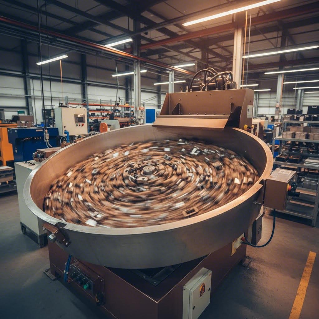
Tumbling (barrel finishing) remains one of the most widely used approaches for removing burrs from stamped parts. Parts are loaded into a rotating barrel along with abrasive media and a liquid compound. As the barrel rotates, parts tumble against each other and the media, gradually wearing away burrs and improving surface finish. The process is simple, relatively inexpensive, and handles large batch sizes efficiently. However, tumbling can cause part-on-part damage with delicate components and offers limited precision since all surfaces receive similar treatment.
Vibratory finishing takes a gentler approach that works well for more delicate stamped parts. Instead of tumbling, parts and media vibrate together in a bowl or trough-shaped container. The vibratory action creates a gentler rubbing motion that removes burrs while minimizing the risk of part damage. You'll achieve more uniform results than tumbling, and the process accommodates a wider range of part geometries. The tradeoff? Cycle times tend to be longer, and equipment costs run higher than basic tumbling systems.
Belt grinding and sanding offer precision that mass finishing methods can't match. Parts pass against moving abrasive belts that remove burrs along specific edges. This targeted approach works exceptionally well for flat stampings where burrs appear along predictable edge locations. Belt systems can be integrated directly into production lines for continuous processing. The limitation? Complex part geometries with multiple edge orientations require multiple passes or elaborate fixturing.
Brushing uses rotating wire or abrasive-filled brushes to remove machining burrs and break sharp edges. The flexible bristles conform to part contours better than rigid abrasives, making brushing suitable for moderately complex geometries. Brushing excels at producing consistent edge breaks without removing excessive material. However, heavy burrs may require multiple passes or pre-processing with more aggressive methods.
When Manual Deburring Still Makes Sense
You might assume that automation always beats manual labor, but that's not always true for deburring operations. Manual deburring using hand tools, files, scrapers, and abrasive pads remains surprisingly relevant in certain situations.
Consider manual deburring when you're dealing with:
- Low-volume production: When quantities don't justify equipment investment, skilled operators with simple tools often deliver the most economical solution.
- Complex geometries: Parts with intricate features, internal passages, or hard-to-reach areas that automated systems can't access effectively.
- Prototype and development work: During the design phase when part geometry may change frequently, flexible manual methods adapt more readily than dedicated equipment.
- Critical precision requirements: Applications where burr removal must be precisely controlled, and experienced operators can make real-time judgments about material removal.
The obvious downsides include inconsistency between operators, higher labor costs for volume production, and ergonomic concerns from repetitive motion. Still, don't dismiss manual methods automatically. Sometimes the simplest approach is genuinely the best choice for your specific situation.
Advanced Deburring Technologies
Thermal energy method (TEM) uses controlled combustion to remove burrs instantly. Parts are placed in a sealed chamber filled with an oxygen and fuel gas mixture. When ignited, the resulting heat flash vaporizes thin burrs while the bulk of the part acts as a heat sink, remaining virtually unaffected. TEM excels at removing burrs from complex internal passages and cross-drilled holes that other methods can't reach. The process handles multiple parts simultaneously with cycle times measured in seconds. Limitations include high equipment costs, the need for careful parameter control, and unsuitability for parts with very thin sections that might be damaged by heat.
Electrochemical deburring (ECD) removes burrs through controlled electrochemical dissolution. The part becomes an anode in an electrolyte solution, and a shaped cathode tool is positioned near the burr location. When current flows, metal dissolves preferentially at the burr's sharp edges where current density concentrates. ECD produces deburred edges with excellent surface finish and no mechanical stress. It's ideal for hardened materials and precision components. However, the process requires custom tooling for each part geometry, making it cost-prohibitive for low volumes.
In-die deburring eliminates secondary operations entirely by incorporating deburring features directly into the stamping die. Shaving stations, burnishing punches, or ironing operations can produce deburred edges as part of the stamping sequence. When feasible, in-die solutions offer the lowest per-part cost since no additional handling or processing is required. The tradeoff involves higher die complexity and cost, plus potential limitations on achievable edge quality compared to dedicated deburring processes.
Complete Method Comparison
Selecting the optimal deburring approach requires weighing multiple factors against your specific requirements. The following comparison table provides a systematic framework for evaluation:
| Deburring Method | Capital Cost | Operating Cost | Precision Level | Throughput | Material Compatibility | Best Applications |
|---|---|---|---|---|---|---|
| Tumbling | Low | Low | Low to moderate | High (batch) | Most metals; avoid delicate parts | High-volume, robust parts; general deburring |
| Vibratory Finishing | Moderate | Low to moderate | Moderate | Moderate to high | Wide range including delicate parts | Precision stampings; complex geometries |
| Belt Grinding | Moderate | Moderate | High | High (inline) | All metals; flat or simple profiles | Flat stampings; continuous production lines |
| Brushing | Low to moderate | Low | Moderate | Moderate to high | All metals; good for contoured surfaces | Edge breaking; light burrs; surface conditioning |
| Manual Deburring | Very low | High (labor) | Variable (operator dependent) | Low | All materials | Low volumes; prototypes; complex internal features |
| Thermal Energy Method | High | Moderate | Moderate to high | Very high | Most metals; avoid thin sections | Internal passages; cross-drilled holes; batch processing |
| Electrochemical Deburring | High | Moderate to high | Very high | Moderate | All conductive metals; ideal for hardened steel | Precision components; aerospace; medical devices |
| In-Die Deburring | High (die modification) | Very low | Moderate to high | Very high | Material dependent on die design | High-volume production; simple edge profiles |
When evaluating these options for your operation, start with your production volume and quality requirements. High-volume applications with moderate precision needs often find mass finishing methods like tumbling or vibratory finishing deliver the best value. Precision-critical parts may justify the higher costs of electrochemical or in-die solutions. And don't overlook the potential for combining methods, such as using vibratory finishing for general deburring followed by manual touch-up on critical features.
Understanding the full spectrum of deburring technologies positions you to match the right method to each application. But what if your volumes justify even more sophisticated solutions? Automation and robotic deburring systems offer additional capabilities worth exploring.
Automation Solutions for High-Volume Deburring
Imagine running 50,000 stamped parts per shift and needing every single edge to meet identical quality standards. Manual deburring simply can't deliver that consistency, and even traditional mass finishing methods introduce variability between batches. When production volumes climb into the tens of thousands daily, automation becomes less of a luxury and more of a strategic necessity for how to get rid of burrs efficiently and repeatably.
So what exactly is deburr automation, and when does investing in it make sense? To define deburr in an automated context, we're talking about systems that remove unwanted edge material without direct human manipulation of each part. These range from simple mechanized fixtures to sophisticated robotic cells with force feedback and vision systems. The right solution depends on your volume, part complexity, quality requirements, and existing production infrastructure.
Robotic Deburring Integration for Consistent Quality
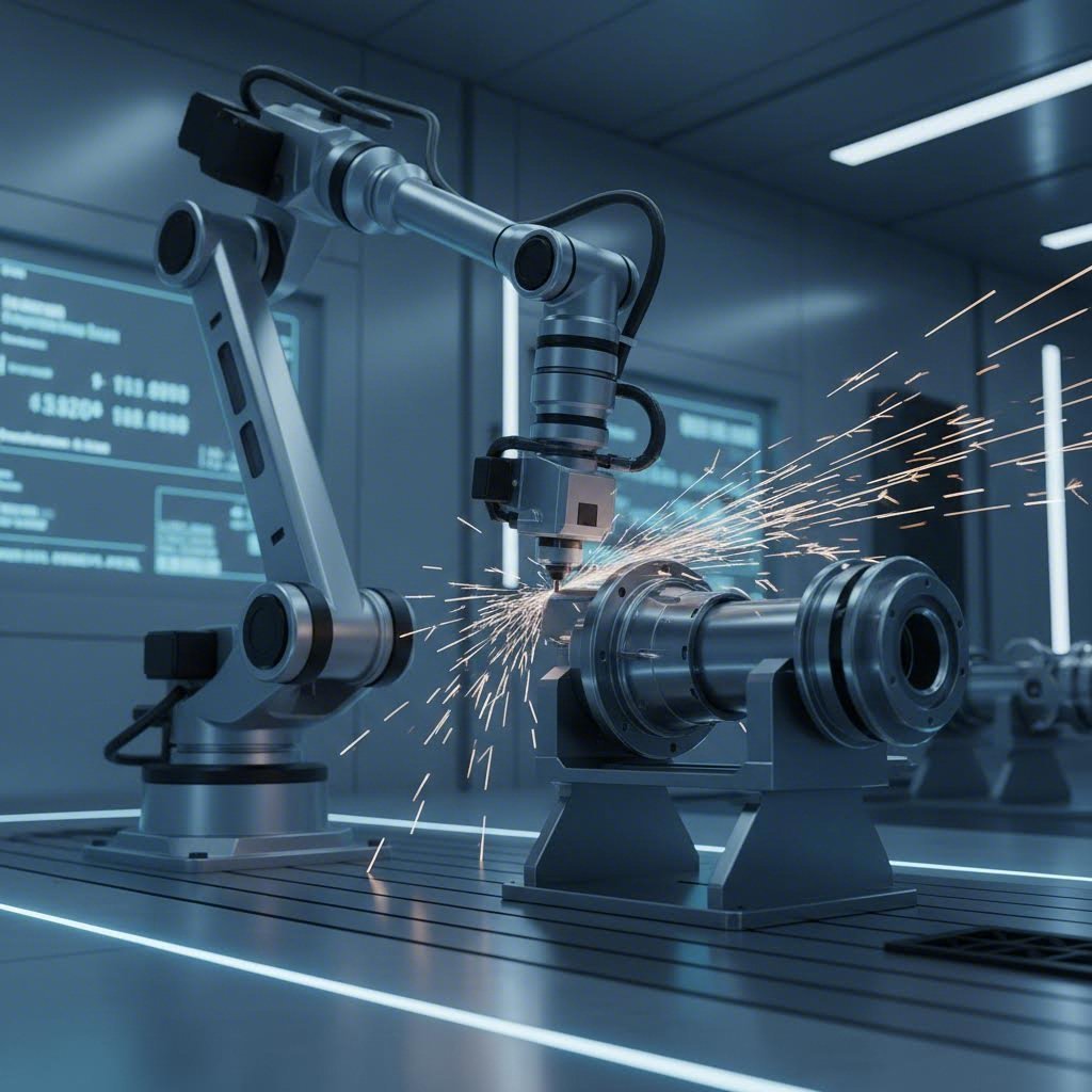
Robotic deburring cells have transformed what's possible in high-volume stamping operations. Unlike manual operators who fatigue and vary their technique throughout a shift, robots deliver identical tool paths, contact pressures, and processing times on part number one and part number ten thousand.
A typical robotic deburring system consists of an industrial robot arm, an end-of-arm tool (often a pneumatic or electric spindle holding grinding, brushing, or cutting tools), and a workholding fixture. Advanced systems incorporate force control sensors that maintain consistent pressure against the workpiece regardless of minor dimensional variations. Vision systems can inspect parts before processing, adapting the deburring path to actual burr locations rather than assumed positions.
The quality consistency benefits extend beyond just uniform edge conditions. Robots eliminate the human factors that introduce variability: fatigue, distraction, inconsistent technique, and subjective quality judgments. Every part receives precisely the same treatment, which dramatically simplifies quality control and reduces customer complaints about inconsistent edge quality.
Integration with existing stamping lines requires careful planning. You'll need to consider part presentation, meaning how parts reach the robot and in what orientation. Conveyors, bowl feeders, or direct pickup from the press output can all work depending on your layout. Cycle time synchronization matters too since the deburring cell must keep pace with stamping production rates without becoming a bottleneck.
Eliminating Secondary Operations Through In-Die Solutions
What if you could eliminate the deburring step entirely? In-die deburring accomplishes exactly that by building burr removal features directly into your stamping tooling. When it works, this approach offers the lowest possible per-part cost since parts exit the press ready for the next operation with no additional handling required.
Several in-die techniques can achieve deburred edges. Shaving operations use a close-fitting punch and die to remove a thin layer of material along the cut edge, taking the burr with it. Burnishing punches can iron over burrs, folding them flat against the part surface. Coining operations apply localized pressure to crush and smooth burr edges. The choice depends on material properties, part geometry, and edge quality requirements.
However, in-die solutions aren't universally applicable. Implementation considerations include:
- Part geometry constraints: In-die deburring works best for accessible edge profiles. Complex three-dimensional parts with burrs on multiple planes may not be candidates.
- Die complexity and cost: Adding shaving or burnishing stations increases die build cost and requires more sophisticated design engineering.
- Maintenance requirements: More die stations mean more components that wear and require servicing, potentially increasing downtime.
- Material limitations: Very hard or very soft materials may not respond well to in-die deburring techniques.
The decision between in-die solutions and post-process deburring often comes down to volume and part lifetime. For parts produced in millions of units over many years, investing in sophisticated in-die tooling pays back handsomely. For shorter runs or parts still undergoing design changes, maintaining flexibility through post-process deburring may be wiser.
When Automation Makes Economic Sense
Not every operation justifies automation investment. The key is calculating your specific return on investment based on actual production parameters rather than assuming automation always wins. Consider these factors when evaluating automation ROI for deburring:
- Annual production volume: Higher volumes spread equipment costs across more parts, improving per-unit economics.
- Current labor costs: Manual deburring labor rates, including benefits and overhead, establish your baseline for comparison.
- Quality cost of poor consistency: Factor in scrap, rework, customer complaints, and returns attributable to inconsistent manual deburring.
- Equipment capital and installation costs: Include robots, tooling, integration engineering, safety guarding, and production downtime during installation.
- Operating costs: Account for energy, consumables, maintenance, and programming time for part changeovers.
- Floor space requirements: Automated cells often require more space than manual stations, which carries its own cost.
- Flexibility needs: If you run many different part numbers with frequent changeovers, programming and fixturing costs accumulate.
Generally, automation becomes compelling when you're processing tens of thousands of similar parts annually, when quality consistency directly impacts customer satisfaction or safety, or when labor availability makes staffing manual deburring stations difficult. Many operations find a hybrid approach works best: automate the high-volume runners while maintaining manual capability for lower-volume or specialty parts.
Whether you choose robotic automation, in-die solutions, or a combination of approaches, understanding your specific requirements against industry standards ensures you're targeting the right edge quality specifications. Different markets have vastly different expectations for what constitutes an acceptable burr.
Industry Standards and Quality Specifications
You've selected your deburring method, optimized your process, and parts are flowing off the line. But here's the question that keeps quality managers awake at night: how do you know if your burr levels are actually acceptable? The answer depends entirely on where those parts end up. A burr on metal that passes inspection for agricultural equipment might cause catastrophic failure in a medical implant or aerospace application.
Understanding industry-specific burr tolerances transforms quality control from guesswork into a data-driven process. Different sectors have developed their own standards based on decades of experience with what works and what fails in their applications. Let's examine what various industries consider acceptable and how you can verify your parts meet those requirements.
Industry Standards for Acceptable Burr Heights
The Precision Metalforming Association Design Guidelines provide valuable context for understanding industry expectations, but specific requirements vary significantly across sectors. What constitutes a "clean edge" in one industry might be completely unacceptable in another.
Automotive applications typically specify burr heights in the range of 0.1 mm to 0.3 mm (0.004 to 0.012 inches) for most stamped components. Safety-critical parts like brake components, fuel system elements, and restraint system hardware often require tighter limits of 0.05 mm to 0.1 mm. The concern isn't just assembly interference. Sharp burrs can cut wiring insulation, damage seals, or create stress concentration points that lead to fatigue failures over the vehicle's lifetime.
Aerospace requirements push tolerances even tighter, often demanding burr heights below 0.05 mm (0.002 inches) for structural components. In aviation, even microscopic burrs can initiate fatigue cracks under cyclic loading conditions. Additionally, any loose burr that detaches during service becomes foreign object debris (FOD) that can damage engines or control systems. Aerospace specifications frequently require not just burr height limits but also edge break requirements specifying minimum radius on all cut edges.
Electronics and electrical components present unique challenges where burrs affect functionality rather than just assembly. Circuit board shields, connector housings, and EMI shielding components often require burr heights below 0.1 mm to prevent electrical shorts or interference with mating components. Corner protectors metal and similar enclosure parts need smooth edges to avoid damaging cables or creating safety hazards during installation.
Medical device manufacturing demands the most stringent burr control of any industry. Implantable devices and surgical instruments typically require burrs below 0.025 mm (0.001 inches) or complete burr-free edges verified under magnification. Any burr on a medical component represents a potential source of tissue damage, bacterial colonization, or particle generation within the body. Regulatory requirements including FDA guidelines and ISO 13485 certification mandate documented burr inspection and control procedures.
The following table summarizes typical requirements across major industry sectors:
| Industry Sector | Typical Burr Height Tolerance | Critical Considerations |
|---|---|---|
| General Industrial | 0.2 mm to 0.5 mm (0.008 to 0.020 in) | Assembly fit; operator safety; coating adhesion |
| Automotive (non-critical) | 0.1 mm to 0.3 mm (0.004 to 0.012 in) | Wire protection; seal integrity; paint adhesion |
| Automotive (safety-critical) | 0.05 mm to 0.1 mm (0.002 to 0.004 in) | Fatigue life; brake performance; restraint systems |
| Aerospace (structural) | Below 0.05 mm (0.002 in) | Fatigue crack initiation; FOD prevention; edge break requirements |
| Electronics/Electrical | 0.05 mm to 0.1 mm (0.002 to 0.004 in) | Short circuit prevention; EMI shielding integrity; connector mating |
| Medical Devices | Below 0.025 mm (0.001 in) or burr-free | Tissue compatibility; particle generation; sterilization; regulatory compliance |
| Consumer Products | 0.1 mm to 0.3 mm (0.004 to 0.012 in) | User safety; aesthetic quality; product liability |
Quality Verification and Measurement Protocols
Knowing your target specification is only half the battle. You also need reliable methods to verify that parts actually meet those requirements. The measurement approach you choose should match both your tolerance requirements and production volumes.
Visual inspection remains the most common first-line quality check, but it has significant limitations. Human inspectors can reliably detect burrs larger than about 0.3 mm under good lighting conditions, but smaller burrs often escape notice, especially late in a shift when fatigue sets in. For lawn burrs and other outdoor equipment where tolerances are generous, visual inspection may suffice. For precision applications, it's merely a screening step before more rigorous measurement.
Tactile inspection using fingertips or a fingernail can detect burrs that aren't visible. Trained inspectors develop sensitivity to edge conditions that complements visual checks. However, this method is subjective, non-quantitative, and poses potential injury risks with sharp burrs.
Optical measurement systems provide quantitative burr height data with good repeatability. Optical comparators project magnified part profiles onto a screen where burr heights can be measured against reference scales. More advanced vision systems use cameras and image processing software to automatically detect and measure burrs, enabling 100% inspection at production speeds.
Contact measurement using profilometers or coordinate measuring machines (CMMs) delivers the highest precision for critical applications. Stylus-based profilometers trace across the edge and record height variations with micrometer-level resolution. CMMs can measure burr heights at specific locations defined in the inspection program. While slower than optical methods, contact measurement provides the traceability and precision that aerospace and medical applications demand.
Cross-sectional analysis offers the definitive assessment of burr characteristics but destroys the sample part. Sectioning through the burr location, mounting in resin, polishing, and examining under magnification reveals true burr height, rollover extent, and edge condition details. This technique is typically reserved for process qualification rather than production inspection.
Effective quality verification requires matching your inspection method to your tolerance requirements:
- Tolerances above 0.3 mm: Visual inspection with adequate lighting and trained personnel may be sufficient.
- Tolerances from 0.1 mm to 0.3 mm: Optical comparators or automated vision systems provide reliable verification.
- Tolerances below 0.1 mm: Contact profilometry or high-resolution optical systems become necessary.
- Medical and aerospace critical applications: Combine multiple methods with documented procedures and statistical process control.
Whatever methods you employ, establish clear accept/reject criteria, train inspectors consistently, and maintain calibrated equipment. Documentation of inspection results provides the traceability that quality auditors and customers increasingly demand. When your burr specifications align with industry standards and your verification methods confirm compliance, you've built a quality system that protects both your customers and your reputation.
Understanding specifications and verification is essential, but quality comes at a cost. The real question for many manufacturers is how to balance burr-related quality investments against their actual return on investment.
Cost Analysis and ROI Considerations
Here's a scenario you might recognize: your stamping operation produces parts that technically meet specifications, but burr removal expenses eat into margins month after month. You know there's a better way, but how do you build the business case for investing in prevention or upgrading your deburring cost analysis capabilities? The challenge is that burr-related costs hide in plain sight, scattered across multiple budget lines where they escape scrutiny.
Most manufacturers track obvious metrics like scrap rates and direct labor hours. But the true cost of metal burs extends far beyond these visible line items. When you account for every downstream impact, the financial case for addressing burr issues systematically becomes compelling. Let's break down where the money actually goes and how to evaluate your options with clear-eyed ROI analysis.
Calculating the True Cost of Burr-Related Quality Issues
Think of burr costs as an iceberg. The visible portion above the waterline includes the expenses you already track. Below the surface lurks a much larger mass of hidden costs that rarely appear in standard reports but drain profitability just the same.
Direct visible costs are the easiest to quantify:
- Scrap rates: Parts rejected for excessive burrs represent lost material, machine time, and labor investment. Even a 2% scrap rate adds up quickly at high volumes.
- Rework labor: Every hour your team spends manually touching up burrs is an hour not spent on value-adding activities. Track this time carefully since it often exceeds estimates.
- Deburring equipment and consumables: Tumbling media, grinding belts, electrochemical solutions, and equipment maintenance represent ongoing operational expenses.
Hidden costs require deeper investigation but often exceed the visible expenses:
- Customer returns and complaints: Each returned shipment triggers inspection, replacement production, expedited shipping, and administrative overhead. Beyond direct costs, returns damage customer relationships and future order potential.
- Warranty claims and liability: When burrs cause downstream failures, especially in safety-critical applications, the financial exposure can be enormous. Legal defense costs, settlements, and insurance premium increases all factor in.
- Production slowdowns: Workers handling burred parts move more carefully to avoid injury, reducing throughput. Assembly operations slow down when parts don't fit properly due to burr interference.
- Inspection overhead: Stricter inspection protocols for burr-prone parts consume quality department resources and add cycle time.
- Tooling wear acceleration: Running with suboptimal clearances to minimize burrs can accelerate punch and die wear, shortening maintenance intervals and increasing tooling costs.
To calculate your true burr-related costs, gather data from across your operation. Pull scrap reports, rework time logs, customer complaint records, and warranty claims. Interview production supervisors about handling time impacts and quality managers about inspection requirements. The total often surprises managers who assumed burrs were a minor nuisance rather than a significant profit drain.
ROI Framework for Deburring Method Selection
Once you understand your current cost baseline, you can evaluate improvement options with real numbers rather than assumptions. Whether you're considering upgraded deburring equipment, die modifications for in-die solutions, or automation investments, the same fundamental ROI framework applies.
Step one: Establish your current cost per part for burr-related activities. Divide your total annual burr costs by annual production volume to get a per-unit figure. This becomes your benchmark for comparison.
Step two: Calculate the per-part cost for each alternative approach. Include capital equipment amortized over expected service life, operating costs like labor, energy, and consumables, plus any maintenance and downtime expenses. Don't forget to account for quality improvements that reduce scrap and returns.
Step three: Compare alternatives on a total cost basis, not just capital investment. A more expensive system that dramatically reduces operating costs and quality failures often delivers better ROI than a cheaper option with ongoing inefficiencies.
In high-volume stamping operations, investing in burr prevention through optimized die design and process control almost always delivers superior returns compared to adding removal capacity after the fact. Prevention eliminates the problem at its source, while removal merely treats the symptom at ongoing cost.
Consider this example: a stamper producing 500,000 parts annually spends $0.12 per part on burr-related costs including scrap, manual deburring labor, and customer quality issues. That's $60,000 annually. Investing $40,000 in die modifications and process optimization that reduces burr formation by 80% drops the per-part cost to $0.024, saving $48,000 per year. The payback period? Less than ten months.
The prevention-versus-removal decision typically favors prevention when:
- Production volumes exceed 100,000 parts annually for a given part number
- Parts remain in production for multiple years, amortizing prevention investments
- Quality requirements are stringent enough that removal alone can't consistently meet specifications
- Labor costs make manual deburring economically unsustainable
Conversely, post-process removal may make more sense for lower volumes, frequently changing part designs, or applications where some burr removal will always be necessary regardless of prevention efforts.
The most sophisticated operations blend both strategies. They invest in prevention to minimize burr formation at the source, then apply efficient removal methods to handle whatever burrs remain. This layered approach optimizes total cost while ensuring consistent quality. With clear cost data and ROI analysis guiding your decisions, you can build a burr management strategy that satisfies both the quality team and the finance department.
Implementing a Complete Burr Management Strategy
You've now explored every dimension of burr formation, prevention, removal, and quality verification. But here's the real question: how do you pull all these pieces together into a cohesive burr management strategy that delivers consistent results day after day? The answer lies in treating burr control not as a collection of isolated fixes but as an integrated lifecycle that begins with die design and extends through final quality verification.
Think of effective stamping quality control as a continuous loop rather than a linear process. Each stage informs the others. Insights from quality verification feed back into process optimization. Removal method performance influences die design decisions for future tooling. When you connect these elements systematically, you create a self-improving system that drives burr levels lower over time while reducing total costs.
Building a Systematic Burr Management Program
A comprehensive burr prevention program follows a clear progression: prevent what you can, optimize what remains, remove what's necessary, and verify everything meets specifications. Each stage builds on the previous one, creating multiple layers of defense against quality escapes.
Stage one: Prevention through die design establishes your foundation. The decisions made during tooling development lock in performance characteristics that no amount of downstream adjustment can overcome. Proper punch-to-die clearances matched to your specific material, optimized cutting edge geometry, and thoughtful station sequencing in progressive dies all contribute to minimal burr formation from the start.
This is where working with experienced stamping partners makes a significant difference. Companies that leverage advanced CAE simulation during die development can predict burr formation patterns before cutting steel, allowing design refinements that prevent problems rather than reacting to them. For example, Shaoyi's precision stamping die solutions utilize CAE simulation specifically to identify and eliminate potential burr sources during the design phase, achieving a 93% first-pass approval rate that reflects this proactive engineering approach.
Stage two: Process optimization fine-tunes your operation for minimum burr formation within the constraints of your existing tooling. This involves dialing in tonnage settings, stroke speeds, and lubrication for each material and part combination. Establish baseline parameters during initial production runs, then refine based on measured results. Document optimal settings so they're reproducible across shifts and operators.
Stage three: Removal method selection addresses burrs that prevention and optimization can't eliminate. Match your deburring approach to production volumes, part geometry, quality requirements, and cost constraints. Remember that the least expensive removal method isn't always the best choice since quality consistency and throughput requirements may justify higher-capability solutions.
Stage four: Quality verification closes the loop by confirming that parts actually meet specifications and providing data to improve earlier stages. Implement inspection methods appropriate to your tolerance requirements. Track burr measurements over time to identify trends that signal tooling wear or process drift before parts fail quality checks.
Partnering with Quality-Focused Stamping Specialists
Implementing a world-class burr management program requires expertise that many organizations don't have in-house. The difference between struggling with recurring burr issues and achieving consistently clean edges often comes down to working with stamping partners who understand the full lifecycle approach.
What should you look for in a stamping partner? Certifications matter because they demonstrate documented quality systems. For automotive applications, IATF 16949 certification indicates that a supplier has implemented rigorous quality management processes aligned with OEM requirements. This certification, held by manufacturers like Shaoyi, directly relates to the automotive industry burr tolerance standards discussed earlier and provides confidence that your parts will meet specifications consistently.
Rapid prototyping capabilities accelerate your burr prevention strategy by enabling quick validation of die design concepts. When you can test tooling approaches in as little as five days rather than weeks, you gain the flexibility to experiment with different clearances, edge geometries, and station configurations before committing to production tooling. This iterative approach identifies optimal burr prevention strategies faster and at lower cost than traditional methods.
Here are the key action items for implementing your burr management program:
- Audit your current state: Document existing burr levels, costs, and pain points across all part numbers to establish a baseline for improvement.
- Prioritize by impact: Focus initial efforts on high-volume parts and applications where burr quality directly affects customer satisfaction or safety.
- Invest in prevention: Allocate resources to die design optimization and CAE simulation rather than adding removal capacity for problems that shouldn't exist.
- Standardize processes: Create documented procedures for process parameters, maintenance intervals, and inspection protocols that ensure consistency.
- Implement feedback loops: Connect quality data to upstream decisions so that burr measurement results drive continuous improvement in die design and process settings.
- Partner strategically: Evaluate stamping suppliers based on their engineering capabilities and quality certifications, not just piece price.
- Track and celebrate progress: Monitor key metrics like burr-related scrap rates, deburring costs per part, and customer complaints to quantify improvement and maintain momentum.
The journey from hidden burr costs to consistently clean edges doesn't happen overnight. But with a systematic approach that addresses prevention, optimization, removal, and verification as an integrated system, you'll see measurable improvements within months rather than years. The manufacturers who treat burr management as a strategic priority rather than an unavoidable nuisance consistently outperform competitors on quality, cost, and customer satisfaction.
Your next step? Start with that baseline audit. Understand where you are today, and the path forward becomes clear.
Frequently Asked Questions About Eliminating Burrs in Metal Stamping
1. How to remove burrs on metal?
The most effective burr removal methods include vibratory finishing, barrel tumbling, manual deburring with files and scrapers, thermal energy deburring, and electrochemical deburring. For high-volume production, mechanical methods like tumbling and vibratory finishing offer the best balance of throughput and cost. Complex parts with internal passages may require thermal energy methods, while precision components benefit from electrochemical deburring. Working with IATF 16949 certified manufacturers who utilize CAE simulation can help prevent burrs at the source, reducing removal needs significantly.
2. How should burrs be removed?
Burr removal method selection depends on production volume, part geometry, and quality requirements. Small burrs on rotating parts can be removed by applying a file to the burr during rotation. Drilling-generated burrs are often removed using a larger drill bit rotated by hand. For stamped parts, mass finishing methods like tumbling work well for robust components, while vibratory finishing suits delicate parts. Critical applications may require electrochemical deburring for precision control without mechanical stress on the workpiece.
3. Which tools are used to remove burrs from metal edges?
Common deburring tools include hand files, scrapers, deburring blades, and abrasive brushes for manual operations. Automated solutions use wire brushes, grinding wheels, and specialized brush tools that conform to workpiece contours. For high-precision work, electrochemical deburring uses shaped cathode tools positioned near burr locations. In-die solutions incorporate shaving stations and burnishing punches directly into stamping tooling, eliminating secondary operations entirely for high-volume production.
4. What causes burrs in metal stamping?
Burrs form during the shearing process when the punch descends through the material. Key causes include improper die clearance (too tight causes secondary shearing, too loose creates rollover burrs), worn or dull cutting edges, insufficient tonnage, inadequate lubrication, and die misalignment. Material properties also influence burr formation, with ductile materials like aluminum producing larger burrs than harder steels. Systematic diagnosis by examining burr location, size, and direction helps identify specific root causes for targeted correction.
5. What is the ideal die clearance to prevent burrs?
Optimal die clearance varies by material type and thickness. For mild steel, 5% to 10% of material thickness per side works well. Aluminum requires larger clearances of 8% to 12% due to its ductility, while stainless steel performs better with tighter clearances around 4% to 8% to minimize work-hardening effects. Proper clearance allows clean fracture with minimal plastic deformation. Advanced manufacturers use CAE simulation during die design to optimize clearance before production, achieving first-pass approval rates exceeding 90%.