 Small batches, high standards. Our rapid prototyping service makes validation faster and easier —

Springback Compensation Methods That End Sheet Metal Guesswork Forever

Understanding Springback in Sheet Metal Forming
Have you ever bent a piece of metal only to watch it partially return to its original shape the moment you release pressure? That frustrating phenomenon has a name, and understanding it is the first step toward mastering precision sheet metal fabrication.
Springback is the elastic recovery phenomenon in sheet metal forming where material partially returns toward its original shape after forming forces are removed, caused by the release of stored elastic strain energy within the metal.
This elastic recovery behavior represents one of the most persistent challenges in metal forming operations. When you bend, stamp, or draw sheet metal, the material experiences both plastic deformation (permanent change) and elastic deformation (temporary change). While the plastic deformation remains after forming, the elastic portion springs back, altering your carefully planned final geometry.
The Physics Behind Elastic Recovery in Metal Forming
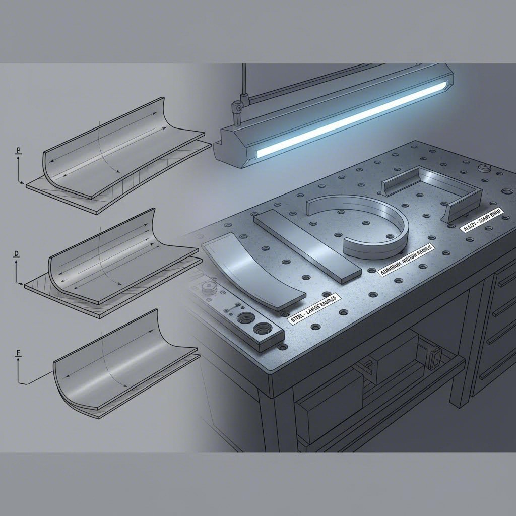
Imagine stretching a rubber band. When you let go, it snaps back because of stored elastic energy. Sheet metal behaves similarly, though to a lesser degree. During forming, the outer fibers of a bent section stretch while inner fibers compress. This creates a stress distribution through the material thickness.
Once forming pressure releases, the elastic component of these stresses relaxes. The metal doesn't return completely flat, but it does move partially back toward its original state. The magnitude of this spring back depends on several interrelated factors:
- Material yield strength and elastic modulus ratio
- Bend radius relative to material thickness
- Work hardening characteristics of the alloy
- Tooling geometry and forming speed
Why Dimensional Accuracy Depends on Springback Control
Consider a part designed with a precise 90-degree bend. Without proper compensation, that bend might actually measure 92 or 93 degrees after forming. For a single component, this deviation might seem minor. However, when that part must fit precisely with mating components in an assembly, even small angular errors compound into serious fit and function problems.
Tight tolerances in modern manufacturing demand predictable, repeatable results. Engineers cannot simply accept whatever geometry emerges from the forming process. They need methods to anticipate elastic recovery and compensate for it before the first production part is made.
Critical Industries Affected by Springback Challenges
The impact of springing back extends across virtually every sector that relies on formed sheet metal components:
- Automotive manufacturing: Body panels, structural members, and chassis components require precise fit for crash safety, aerodynamics, and assembly efficiency
- Aerospace applications: Fuselage skins, wing components, and structural frames demand extremely tight tolerances where spring back errors could compromise structural integrity
- Appliance production: Enclosures, brackets, and internal components must align properly for both function and aesthetic quality
- Electronics enclosures: Precision housings require consistent dimensional accuracy for component mounting and electromagnetic shielding
Each of these industries has developed specialized approaches to address elastic recovery, yet the fundamental challenge remains the same. Effective springback compensation methods transform unpredictable forming outcomes into reliable, repeatable precision. The following sections explore exactly how manufacturers achieve this control across different materials, processes, and production scenarios.
Material-Specific Springback Behavior and Factors
Not all metals spring back equally. When you're working with a sheet metal design guide or planning a forming operation, understanding how different materials behave can mean the difference between first-pass success and costly rework. The material sitting on your press fundamentally determines how much elastic recovery you'll face and which compensation strategy will work best.
Three key material properties drive springback magnitude:
- Yield strength to elastic modulus ratio: Higher ratios mean more elastic strain stored during forming, leading to greater metal back movement after release
- Work hardening rate: Materials that harden quickly during deformation store more elastic energy in the formed zone
- Anisotropy: Directional property variations create unpredictable springback patterns that complicate compensation
How AHSS Presents Unique Springback Challenges
Advanced High-Strength Steels have transformed automotive manufacturing by enabling lighter, safer vehicle structures. However, these materials present significant forming challenges. With yield strengths often exceeding 600 MPa and reaching above 1000 MPa in some grades, AHSS stores substantially more elastic energy during forming compared to conventional steels.
Consider what happens during sheet metal stretching with dual-phase or martensitic steels. The high-strength microstructure resists permanent deformation, meaning a larger portion of the applied strain remains elastic. When forming pressure releases, this elastic component drives pronounced springback that can exceed what manufacturers experience with mild steel by a factor of two or more.
The challenge intensifies because AHSS often exhibits complex work hardening behavior. Unlike mild steel with relatively predictable hardening curves, many advanced grades show discontinuous yielding, bake hardening effects, or strain-rate sensitivity. These factors make simulation-based compensation essential rather than optional.
Aluminum vs Steel Springback Behavior Differences
Aluminum alloys present a different springback profile than steel, and understanding these differences prevents costly trial-and-error cycles. While aluminum has a lower elastic modulus than steel (approximately 70 GPa versus 210 GPa), this doesn't automatically mean less springback.
The critical factor is the yield strength to modulus ratio. Many aluminum alloys used in automotive and aerospace applications have yield strengths approaching those of mild steel, but with only one-third the stiffness. This combination produces elastic strains roughly three times higher for equivalent stress levels, often resulting in springback magnitudes that surprise engineers accustomed to steel forming.
Additionally, aluminum alloys frequently exhibit:
- Greater sensitivity to bend radius variations
- More pronounced anisotropic behavior affecting directional springback
- Age-hardening responses that can alter properties between forming and final use
Material Selection Impact on Compensation Strategy
Your material choice directly dictates which springback compensation methods will prove effective. A strategy that works perfectly for mild steel stamping may fail completely with AHSS or aluminum applications.
| Material Type | Relative Springback Magnitude | Key Influencing Factors | Recommended Compensation Approach |
|---|---|---|---|
| Mild Steel (DC04, SPCC) | Low to Moderate | Consistent work hardening, predictable behavior | Empirical overbending, standard die modification |
| Stainless Steel (304, 316) | Moderate to High | High work hardening rate, variable anisotropy | Increased overbend angles, radius compensation |
| Aluminum Alloys (5xxx, 6xxx) | High | Low modulus, high yield/modulus ratio, anisotropy | Simulation-driven compensation, variable binder force |
| AHSS (DP, TRIP, Martensitic) | Very High | Ultra-high strength, complex hardening, strain sensitivity | CAE simulation essential, multi-step forming, post-stretch |
For mild steel applications, experienced toolmakers can often apply empirical compensation factors based on historical data. The material behaves predictably, and simple overbending calculations frequently deliver acceptable results.
Moving up the strength spectrum, stainless steels require more aggressive compensation. Their higher work hardening rates create larger elastic strain gradients through the bend zone, demanding careful attention to tooling radii and clearances.
When forming aluminum or AHSS, empirical approaches alone typically prove insufficient. The material variability and high springback magnitudes necessitate simulation-based prediction and often require multiple compensation iterations before achieving target geometry. Understanding these material-specific behaviors positions you to select appropriate methods from the complete range of compensation techniques available.
Complete Comparison of Springback Compensation Methods
Now that you understand how different materials behave, the next question becomes: which compensation technique should you actually use? The answer depends on your specific forming operation, part complexity, and production requirements. Let's break down each major approach so you can make informed decisions for your applications.
Springback compensation methods generally fall into three mechanism-based categories: techniques that reduce elastic strains during forming, approaches that redistribute strain patterns, and methods that lock strains into the final part geometry. Each serves different manufacturing scenarios, and understanding their mechanisms helps you select the right tool for the job.
Displacement Adjustment Method Explained
Displacement Adjustment (DA) represents one of the most widely used compensation strategies in sheet metal stretch forming and stamping operations. The concept is straightforward: modify the tooling geometry so that after elastic recovery occurs, the part settles into the desired final shape.
Imagine you need a 90-degree bend, but your material springs back 3 degrees. With displacement adjustment, you design your die to form a 87-degree bend initially. When the part releases and springs back those 3 degrees, you achieve your target geometry. This approach works by anticipating the springback magnitude and pre-compensating the tool surfaces accordingly.
The method becomes more sophisticated for complex geometries. Engineers use CAE simulation to predict springback across the entire part surface, then systematically adjust die geometry point-by-point. Modern software can automate this iterative process, reducing what once required multiple physical tryout cycles to just a few digital iterations.
Spring Forward Technique Applications
The Spring Forward (SF) method takes a different mathematical approach to achieve similar results. Rather than simply adding compensation to the die shape, this technique calculates what tool geometry would produce zero springback if the material properties were inverted.
In practical terms, SF creates a compensated die surface where the part "springs forward" into the target shape rather than springing back away from it. This method often produces more stable results for parts with complex curvature because it accounts for the complete strain distribution rather than treating springback as a simple angular correction.
Spring banding effects in sheet metal flaring technology applications particularly benefit from the SF approach. When forming flanged or flared geometries, the strain gradients through the formed zone create complex springback patterns that simple overbending cannot fully address.
Overbending and Die Modification Strategies
Overbending remains the most intuitive compensation method, especially for press brake operations and simple bending applications. You bend the material past the target angle, allowing springback to bring it back to the desired position. While conceptually simple, effective overbending requires accurate prediction of the springback magnitude.
Die geometry modification extends this concept to stamping and deep drawing operations. Tooling engineers adjust:
- Punch and die radii to control strain distribution
- Clearances between forming surfaces
- Surface profiles to pre-compensate for elastic recovery
- Draw bead configurations to lock material strains
Variable binder force techniques add another dimension to compensation. By controlling the blank holder pressure during forming, engineers can influence how material flows into the die cavity. Higher binder forces increase stretching, which can reduce springback by shifting more deformation into the plastic range.
Post-stretch and stake bead approaches work on a different principle entirely. Rather than compensating for springback, these methods lock the formed geometry by adding tension or local deformation after the primary forming operation. Stake beads create localized plastic zones that resist elastic recovery in the surrounding material.
| Method Name | Mechanism Description | Best Applications | Advantages | Limitations | Complexity Level |
|---|---|---|---|---|---|
| Displacement Adjustment (DA) | Modifies die geometry to pre-compensate for predicted springback | Complex stampings, automotive panels, multi-surface parts | Handles complex geometries, simulation-compatible, iterative refinement possible | Requires accurate springback prediction, multiple iterations may be needed | Medium to High |
| Spring Forward (SF) | Calculates inverse springback to create forward-compensated tool surfaces | Curved panels, flanged parts, sheet metal flaring technology applications | Mathematically robust, accounts for complete strain distribution | Complex calculation, requires advanced simulation software | High |
| Overbending | Forms material past target angle, allowing springback to achieve desired geometry | Press brake bending, simple bends, V-bending operations | Simple to implement, low tooling cost, easy to adjust empirically | Limited to simple geometries, requires trial iterations for new materials | Low |
| Die Geometry Modification | Adjusts punch/die radii, clearances, and profiles for compensation | Stamping dies, progressive tooling, draw operations | Built into tooling, no process changes required | Fixed compensation, difficult to adjust after tool completion | Medium |
| Variable Binder Force | Controls blank holder pressure to influence material flow and strain levels | Deep drawing, sheet metal stretch forming, complex draws | Adjustable during production, can optimize in real-time | Requires controllable press systems, adds process variables | Medium |
| Post-Stretch | Applies tension after forming to convert elastic strain to plastic | Aluminum panels, aerospace skins, large curved surfaces | Highly effective for high-springback materials, excellent final geometry | Additional equipment required, longer cycle times | High |
| Stake Beads | Creates localized plastic zones that resist elastic recovery | Flanges, hems, areas requiring locked geometry | Simple tooling addition, effective for local springback control | May affect part appearance, limited to suitable locations | Low to Medium |
| Over-Forming | Forms part beyond final shape in initial operation, secondary operation achieves target | Multi-stage stamping, progressive dies, parts with severe springback | Can achieve geometries impossible in single operations | Additional tooling stages, increased cycle time and cost | Medium to High |
Selecting among these methods rarely involves choosing just one approach. Complex parts often require hybrid strategies that combine multiple techniques. For instance, an automotive body panel might use displacement-adjusted die surfaces, variable binder force during forming, and stake beads on critical flanges to achieve final dimensional targets.
The key is matching compensation complexity to your actual requirements. Simple bends in mild steel rarely justify sophisticated simulation-based approaches when empirical overbending works reliably. Conversely, AHSS structural components with tight tolerances demand the precision that only CAE-driven compensation can provide. The following sections explore how to choose between simulation-based and empirical approaches for your specific applications.
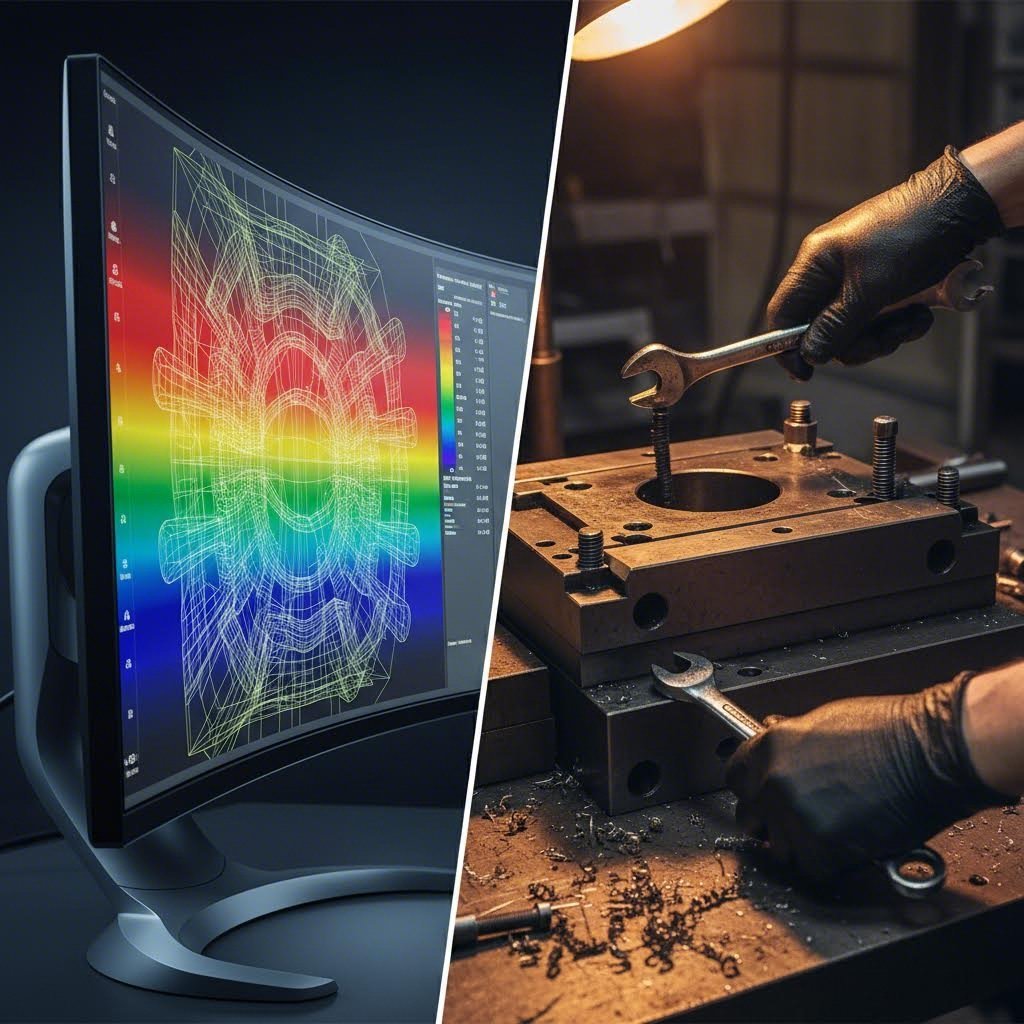
Simulation-Based vs Empirical Compensation Approaches
So you've identified which compensation method fits your application. Now comes the critical decision: should you rely on digital prediction through springback simulation software, or trust empirical trial-and-error methods developed on the shop floor? The answer isn't always straightforward, and choosing wrong can cost you weeks of delays or thousands in unnecessary software investment.
Both approaches have legitimate applications. Understanding when each delivers the best return helps you allocate resources effectively and achieve target geometries faster. Let's break down the decision factors that guide experienced forming engineers.
When Simulation-Based Compensation Is Essential
CAE forming analysis has transformed how manufacturers approach complex springback challenges. Modern simulation software can predict elastic recovery before any physical tooling exists, allowing engineers to iterate digitally rather than cutting steel. This capability becomes essential in specific scenarios where empirical methods simply cannot deliver acceptable results.
Scenarios where simulation-based compensation proves essential:
- Complex three-dimensional geometries: Parts with compound curves, multiple bend lines, or twisted profiles create springback patterns too complex for intuitive prediction
- Advanced High-Strength Steel applications: AHSS materials exhibit unpredictable springback behavior that historical data from mild steel cannot address
- Tight tolerance requirements: When dimensional specifications leave no room for iteration, simulation reduces the gap between first tryout and production approval
- New material grades: Introducing unfamiliar alloys or new supplier material means no empirical baseline exists
- High-cost tooling investments: Progressive dies and transfer tooling costing hundreds of thousands of dollars justify simulation investment to minimize physical modifications
CAE software predicts springback by modeling the complete forming process, tracking stress and strain evolution through each forming stage. After simulating the unloading phase, the software calculates elastic recovery across every point on the part surface. Engineers then apply compensation algorithms—whether displacement adjustment, spring forward, or hybrid approaches—to generate modified die geometries.
The real power emerges through iteration. Rather than building physical tools and measuring actual parts, engineers refine compensation in hours rather than weeks. Metal flare distortion in flanged components, twist in structural rails, and angular deviation in brackets all become visible before the first tool steel is machined.
Empirical Trial-and-Error Method Applications
Despite the capabilities of modern simulation, empirical compensation methods remain valuable and cost-effective for many applications. Experienced toolmakers have developed compensation knowledge over decades that still delivers excellent results under the right conditions.
Scenarios where empirical methods prove most effective:
- Simple bend geometries: Single-axis bends with consistent radii follow predictable springback patterns that historical data addresses reliably
- Established material and process combinations: When you've formed the same material grade on the same equipment for years, documented compensation factors provide proven starting points
- Low-volume production runs: Prototype quantities or short production runs may not justify simulation software costs and learning curves
- Press brake operations: Experienced operators develop intuitive compensation skills that often outperform generic simulation predictions
- Incremental process refinement: When existing tooling produces parts close to specification, small empirical adjustments often reach targets faster than complete re-simulation
Empirical approaches rely on systematic documentation and process discipline. Successful shops maintain compensation databases recording material grades, thicknesses, bend parameters, and resulting springback values. This institutional knowledge becomes invaluable for quoting new jobs and setting up similar parts.
Combining Digital Prediction with Physical Validation
The most sophisticated manufacturers don't view simulation and empirical methods as competing alternatives. Instead, they integrate both into a holistic compensation procedure that leverages the strengths of each approach.
A practical hybrid workflow follows these principles:
- Initial simulation prediction: Use CAE forming analysis to establish baseline compensation geometry before tooling construction begins
- Physical validation with soft tooling: Build prototype tools from lower-cost materials to validate simulation predictions against actual formed parts
- Empirical refinement: Apply measured deviations to fine-tune compensation factors, capturing material batch variations and press characteristics simulation cannot fully model
- Production tool construction: Incorporate validated compensation into hardened production tooling with confidence in dimensional outcomes
- Continuous feedback: Document production results to improve simulation inputs for future projects
This combined approach addresses a fundamental limitation of simulation software: models require accurate material property inputs to generate accurate predictions. Real-world material batches exhibit property variations that even the best material testing programs cannot fully characterize. Physical validation catches these variations before they affect production.
Industry 4.0 digitalization is making hybrid approaches more accessible across manufacturing scales. Cloud-based simulation services reduce software investment barriers for smaller shops. Digital measurement systems accelerate the feedback loop between physical tryout results and simulation model refinement. Even operations that historically relied entirely on empirical methods now benefit from selective simulation application on challenging new projects.
The decision framework becomes clearer when viewed through resource allocation. Invest simulation effort where complexity and risk justify the investment. Apply empirical expertise where experience provides reliable guidance. Most importantly, build the feedback systems that allow each approach to strengthen the other over time. With the right balance established, you're ready to implement specific tooling design strategies that build compensation directly into your dies.
Tooling Design Strategies for Built-In Compensation
You've selected your compensation approach and decided whether simulation or empirical methods fit your application. Now comes the hands-on work: translating those decisions into actual tooling modifications. This is where theory meets shop-floor reality, and where experienced tooling engineers earn their reputation for delivering parts that hit dimensional targets on the first production run.
Tooling compensation design operates through three fundamental mechanisms:
- Reducing elastic strains: Modifying tooling features to minimize the amount of elastic energy stored during forming
- Redistributing strains: Shifting strain patterns to create more uniform stress distributions that spring back predictably
- Locking strains: Adding tooling features that create localized plastic deformation preventing elastic recovery
Understanding which mechanism applies to your specific challenge helps you select the right die geometry modification strategy. Let's explore the practical techniques that deliver reliable compensation results.
Die Geometry Modifications for Springback Control
Die geometry modification represents the most direct path to built-in compensation. Rather than adjusting process parameters or adding secondary operations, you engineer the compensation directly into your tool surfaces. Once the die is built correctly, every part formed inherits that compensation automatically.
Key die geometry modification principles include:
- Overbend angle incorporation: Design punch and die surfaces to form angles beyond the target specification, allowing springback to settle into the desired geometry
- Surface profile compensation: Adjust curved die surfaces using displacement adjustment or spring forward calculations to account for elastic recovery across complex contours
- Crowned surfaces: Add slight convex profiles to nominally flat surfaces, compensating for the elastic curvature that develops after forming
- Asymmetric feature positioning: Offset holes, slots, and locating features to account for predictable dimensional shifts during springback
When modifying die geometry, remember that stamping die adjustment affects the entire forming sequence. Changes to one station in a progressive die can alter material feed and positioning for subsequent operations. Experienced tooling engineers evaluate compensation modifications within the context of the complete process, not as isolated changes.
Radius and Clearance Adjustment Techniques
Punch and die radii exert powerful influence over springback behavior. Sounds complex? The principle is actually straightforward: tighter radii create more severe strain gradients, which typically increase springback magnitude. Larger radii spread deformation over wider zones, often reducing elastic recovery but potentially affecting part functionality.
Practical radius adjustment strategies include:
- Reduced punch radius: Smaller punch radii concentrate strain at the bend apex, increasing plastic-to-elastic strain ratio and reducing springback angle
- Die shoulder optimization: Adjusting die entry radii affects material flow and stress distribution during deep drawing operations
- Radius-to-thickness ratio management: Maintaining optimal R/t ratios for specific materials prevents excessive elastic strain accumulation
- Progressive radius variation: Using slightly different radii across bend length compensates for non-uniform springback in long formed features
Clearance between punch and die surfaces equally impacts springback outcomes. Insufficient clearance causes ironing effects that can reduce springback but risk material damage. Excessive clearance allows material to deform inconsistently, creating unpredictable elastic recovery patterns.
For most steel stamping applications, clearances ranging from 5% to 15% of material thickness produce stable results. Aluminum applications often require tighter clearances due to the material's greater tendency toward surface marking and inconsistent deformation. AHSS materials demand careful clearance optimization because their high strength amplifies the effects of both too-tight and too-loose conditions.
Draw Bead Strategies to Lock Material Strains
Draw bead placement offers tooling engineers a powerful method for controlling springback through strain locking. When material flows over draw beads during forming, it undergoes localized bending and unbending cycles that convert elastic strain to plastic strain. This locked plastic deformation resists springback in surrounding areas.
Effective draw bead strategies follow these principles:
- Strategic positioning: Place beads in regions where springback would otherwise cause the greatest dimensional deviation
- Bead geometry selection: Round beads, square beads, and double beads each create different strain patterns suited to specific material and geometry combinations
- Height and radius optimization: Bead dimensions control restraining force and strain severity—higher beads lock more material but risk splitting thin gauges
- Bead length considerations: Full-perimeter beads provide uniform control; segmented beads allow differential material flow for complex shapes
Draw beads serve double duty in many forming operations. Beyond springback control, they regulate material flow rate into the die cavity, preventing wrinkles while ensuring sufficient stretch. When designing beads for compensation purposes, evaluate their effect on overall formability to avoid creating new problems while solving springback challenges.
Stake beads represent a specialized variation designed specifically for strain locking rather than flow control. Positioned in flanges, hems, or flat areas adjacent to formed features, stake beads create localized plastic zones that anchor the surrounding geometry against elastic recovery. They work particularly well for controlling flange springback and twist in structural components.
The most effective tooling compensation designs combine multiple strategies. A stamping die might incorporate overbent punch geometry, optimized radii at critical bends, and strategically placed draw beads working together to achieve target dimensions. This integrated approach recognizes that springback compensation rarely has a single-point solution—it requires systematic engineering across the entire tool design. With these tooling strategies understood, you're ready to develop a complete framework for selecting the right combination of methods for your specific application.
Method Selection Framework for Your Application
You now understand the available compensation techniques and tooling strategies. But here's the real question: which approach actually makes sense for your specific situation? Choosing the wrong method wastes resources, while selecting the right combination delivers first-pass success and long-term production stability.
The optimal springback compensation selection depends on five interconnected factors: production volume, part complexity, material type, tolerance requirements, and available resources. Let's build a decision framework that matches your unique circumstances to the most effective compensation strategy.
Matching Compensation Methods to Production Volume
Production volume fundamentally shapes your compensation approach. The investment that makes perfect sense for a million-unit automotive program becomes wasteful overkill for a fifty-piece prototype run.
High-volume production (100,000+ parts annually): When you're producing at automotive or appliance scales, upfront simulation investment pays dividends across every part formed. CAE-driven displacement adjustment or spring forward methods justify their cost through reduced tryout iterations and faster production ramp-up. Build compensation directly into hardened production tooling, and document everything for process repeatability.
Medium-volume production (1,000 to 100,000 parts annually): This range offers flexibility. Simulation becomes cost-effective for complex geometries or challenging materials, but simpler parts may not require it. Consider hybrid approaches: use simulation for initial compensation estimates, then refine empirically during soft-tool validation. Balance tooling investment against the cost of potential rework.
Low-volume production (under 1,000 parts annually): Empirical methods often deliver the best value here. Experienced operators can dial in compensation through systematic trial adjustment faster than simulation setup and validation cycles. Focus resources on flexible tooling that allows in-process adjustment rather than heavily engineered compensation built into expensive dies.
Part Complexity and Method Selection
Imagine a simple L-bracket versus a compound-curved automotive fender. These parts demand fundamentally different compensation approaches, regardless of production volume.
Simple geometries (single bends, consistent radii, 2D profiles): Standard overbending calculations handle these reliably. Empirical compensation based on material grade and thickness often reaches target dimensions within one or two iterations. Simulation adds minimal value unless tolerance requirements are exceptionally tight.
Moderate complexity (multiple bends, flanges, shallow draws): Hybrid compensation approaches work well here. Use simulation to identify problem areas and establish baseline compensation, then apply empirical refinement for production optimization. Draw beads and strategic die geometry modifications typically address springback effectively.
High complexity (compound curves, twisted profiles, deep draws with flanges): Full simulation-based compensation becomes essential. The interaction between multiple formed features creates springback patterns impossible to predict intuitively. Expect to combine displacement adjustment, variable binder force, and localized stake beads into integrated compensation strategies.
Resource-Based Decision Framework
Your available resources—both technological and human—constrain practical options. A shop with experienced toolmakers but no simulation software faces different choices than a facility with advanced CAE capabilities but limited hands-on forming expertise.
Evaluate your resource position across these dimensions:
- Simulation software access: Do you have in-house CAE forming analysis capability, or would you need to outsource simulation work?
- Toolmaking expertise: Can your team implement complex die geometry modifications, or are standard tooling approaches more practical?
- Press equipment: Does your equipment support variable binder force control or other advanced process compensation techniques?
- Measurement capability: Can you accurately measure springback on complex geometries to validate compensation effectiveness?
- Timeline constraints: Does your project schedule allow for iterative refinement, or must you achieve target geometry quickly?
Use the following decision matrix to match your production scenario with recommended compensation approaches:
| Production Scenario | Typical Characteristics | Primary Compensation Methods | Secondary/Supporting Methods | Resource Requirements |
|---|---|---|---|---|
| High-Volume Automotive | Complex geometry, AHSS materials, tight tolerances, long production runs | CAE simulation with displacement adjustment or spring forward | Variable binder force, draw beads, stake beads on flanges | Full simulation capability, advanced tooling, process control systems |
| Low-Volume Prototyping | Variable geometries, quick turnaround, flexible specifications | Empirical overbending, adjustable tooling | Basic die geometry modification, operator experience | Experienced toolmakers, flexible equipment, good measurement tools |
| Complex Geometry Parts | Compound curves, multiple forming stages, interacting features | Simulation-driven hybrid approach, multi-step compensation | Post-stretch for aluminum, progressive die compensation | Advanced simulation, skilled die design, iterative validation capability |
| Simple Bend Operations | Single-axis bends, consistent materials, moderate tolerances | Standard overbending, empirical adjustment factors | Radius optimization, clearance control | Basic tooling capability, documented compensation tables |
| AHSS Structural Components | Ultra-high strength, significant springback, crash safety requirements | Mandatory CAE simulation, iterative compensation refinement | Multiple forming stages, post-forming calibration | Specialized simulation expertise, high-tonnage press capability |
Step-by-Step Method Selection Process
When facing a new springback compensation challenge, follow this systematic forming method decision guide to identify your optimal approach:
- Characterize your material: Identify the material grade and determine its relative springback tendency (low for mild steel, high for AHSS and aluminum). This immediately narrows appropriate compensation methods.
- Assess part geometry complexity: Evaluate whether the part involves simple bends, moderate forming, or complex three-dimensional shapes. Higher complexity pushes toward simulation-based approaches.
- Define tolerance requirements: Determine how tight your dimensional specifications are. Tolerances under ±0.5mm typically require simulation-driven compensation for anything beyond simple bends.
- Calculate production volume economics: Estimate total production quantity and compare the cost of simulation investment versus iterative empirical refinement. Higher volumes justify larger upfront investment.
- Inventory available resources: List your simulation capabilities, tooling expertise, equipment features, and timeline constraints. Match these against the requirements for candidate methods.
- Select primary compensation method: Choose the core approach that best fits your material, geometry, tolerance, and volume requirements while remaining achievable with available resources.
- Identify supporting techniques: Determine which secondary methods (draw beads, variable binder force, post-stretch) can enhance your primary compensation approach for challenging features.
- Plan validation strategy: Decide how you'll verify compensation effectiveness—soft tooling tryouts, prototype runs, or simulation validation—before committing to production tooling.
For complex parts requiring hybrid compensation approaches, don't hesitate to combine multiple methods. A structural automotive rail might use simulation-based die geometry compensation as the foundation, add variable binder force control during forming, and incorporate stake beads on critical flanges. Each technique addresses different aspects of the springback challenge, and their combined effect often exceeds what any single method achieves alone.
The goal isn't finding the single "best" method—it's assembling the right combination for your specific application. With your method selection complete, the next step is implementing these techniques through a structured workflow that moves from initial prediction through final validation.
Step-by-Step Implementation Workflow
You've selected your compensation methods and built the right tooling strategies into your design. Now comes the critical phase: actually implementing these techniques on the shop floor. This is where many manufacturers stumble—they understand the theory but struggle to translate it into a repeatable compensation workflow process that delivers consistent results.
The springback implementation steps that follow bridge the gap between academic understanding and practical application. Whether you're launching a new part program or troubleshooting an existing process, this workflow provides the structured approach that eliminates guesswork and accelerates production readiness.
Initial Springback Prediction and Analysis
Every successful compensation project starts with understanding what you're actually dealing with. Before adjusting anything, you need a clear picture of expected springback behavior for your specific material, geometry, and forming conditions.
- Gather material property data: Obtain certified material properties including yield strength, tensile strength, elastic modulus, and work hardening characteristics. For critical applications, consider supplemental testing of actual production material samples.
- Define geometry and tolerance requirements: Document target dimensions, critical features, and acceptable tolerance ranges. Identify which features have the tightest specifications—these drive your compensation priorities.
- Generate initial springback prediction: Use CAE simulation for complex geometries or reference empirical data tables for simpler bends. Document predicted springback magnitude and direction for each critical feature.
- Identify high-risk areas: Flag regions where simulation predicts significant elastic recovery or where tolerances leave minimal margin. These areas require the most attention during compensation design.
- Establish baseline compensation factors: Calculate initial overbend angles, die surface adjustments, or other compensation parameters based on prediction results.
For straightforward applications with mild steel and simple geometries, this analysis phase might take hours. Complex AHSS automotive panels with tight tolerances can require weeks of simulation work before tooling design even begins. Scale your analysis effort to match the risk and complexity of your application.
Iterative Refinement Process
Here's a reality check: your initial compensation rarely delivers perfect results on the first attempt. Even the best simulations cannot capture every variable affecting real-world forming operations. The key to success lies in systematic iterative refinement forming that converges efficiently toward target geometry.
- Build soft tooling or prototype dies: Construct initial tooling from lower-cost materials (aluminum, kirksite, or soft steel) that allow modification. This investment pays dividends by enabling multiple adjustment cycles without scrapping expensive hardened tools.
- Form initial sample parts: Run first-article samples using production-representative material. Control all process variables (press speed, binder force, lubrication) to isolate springback effects from other variation sources.
- Measure dimensional deviations: Use CMM, optical scanning, or fixture-based gauging to quantify actual springback. Compare measured results against predictions and target specifications.
- Analyze deviation patterns: Determine whether deviations are systematic (consistent direction and magnitude) or random (varying between samples). Systematic deviations indicate compensation adjustment opportunities; random variation points to process control issues.
- Calculate compensation corrections: Based on measured deviations, adjust compensation factors. If a feature springs back 2 degrees more than predicted, increase the overbend angle by that amount. For simulation-based approaches, update material models with actual behavior data.
- Modify tooling and repeat: Implement corrections in tooling, form new samples, and measure again. Continue this cycle until all critical features fall within specification.
How many iterations should you expect? Simple parts often converge in two to three cycles. Complex geometries with interacting features may require five or more refinement rounds. Budget your timeline accordingly, and resist the temptation to skip soft-tool validation for high-volume production programs.
Document every iteration meticulously. Record compensation parameters, forming conditions, and resulting measurements. This documentation becomes invaluable for troubleshooting future issues and establishing compensation baselines for similar parts.
Final Validation and Quality Assurance
Once iterative refinement achieves target geometry, you're not quite finished. Final validation criteria stamping programs require confirmation that your compensation solution performs reliably under production conditions—not just during carefully controlled tryout runs.
- Conduct production simulation runs: Form a statistically significant sample (typically 30+ parts) using production equipment, operators, and material lots. This reveals variation that doesn't appear in small tryout batches.
- Perform capability analysis: Calculate Cp and Cpk values for critical dimensions. Most automotive applications require Cpk values of 1.33 or higher; aerospace and medical applications often demand 1.67 or above.
- Validate across material lots: If possible, test parts from multiple material coils or batches. Material property variations between lots can shift springback behavior, and your compensation must accommodate this variability.
- Confirm process window stability: Verify that small variations in process parameters (binder force, press speed, lubrication) don't push parts out of specification. Robust compensation solutions tolerate normal process variation.
- Document final compensation parameters: Create detailed records of all compensation factors, tooling dimensions, and process settings. Include acceptable tolerance ranges for each parameter to guide future production and maintenance.
Acceptable tolerance ranges vary by application and industry. As a general guideline:
- Automotive body panels: ±0.5mm on critical mating surfaces, ±1.0mm on non-critical areas
- Structural components: ±0.3mm to ±0.5mm depending on assembly requirements
- Aerospace applications: Often ±0.2mm or tighter for critical features
- Appliance and general fabrication: ±1.0mm to ±1.5mm typical
The final step in any compensation implementation is creating documentation that ensures process repeatability. Record not just what compensation values you used, but why those values were selected and how they were validated. When tooling requires maintenance or replacement, this documentation enables accurate reproduction without repeating the entire development cycle.
With a validated compensation solution and thorough documentation in place, you're positioned for stable production. However, different forming processes present unique compensation considerations that this general workflow must accommodate. The following section explores how springback behavior and compensation strategies differ across stamping, roll forming, and deep drawing applications.
Process-Specific Compensation Considerations
Your compensation workflow is validated and documented. But here's something many manufacturers overlook: the forming process itself fundamentally changes how springback manifests and which compensation strategies work best. A technique that delivers excellent results in stamping may prove completely ineffective for roll forming or deep drawing applications.
Understanding these process-specific nuances prevents wasted effort and accelerates your path to dimensional accuracy. Let's explore how elastic recovery behaves differently across major forming processes and what that means for your compensation approach.
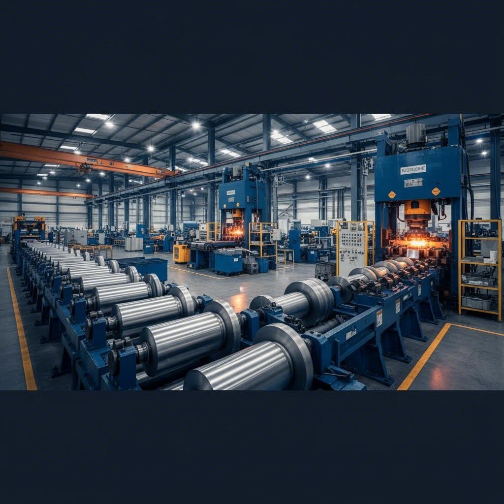
Roll Forming End Flare vs Traditional Springback
Roll forming springback presents unique challenges that often confuse engineers accustomed to stamping or press brake operations. While conventional springback describes angular deviation at bend locations, roll forming introduces a distinct phenomenon called end flare that requires separate consideration.
What exactly is end flare? When material enters and exits roll forming stations, the strip experiences different constraint conditions than the continuous forming zone. At the leading and trailing edges, material lacks the stabilizing influence of adjacent formed sections. This creates localized elastic recovery that causes the part ends to spring outward—often more severely than the body of the profile.
End flare compensation strategies differ from standard springback approaches:
- Additional forming stations: Adding straightening or over-forming rolls near the exit addresses end flare without affecting the main profile
- Variable roll gap adjustment: Tightening clearances at entry and exit stations increases plastic strain in flare-prone zones
- Post-forming calibration: Secondary operations specifically targeting part ends can correct flare after primary forming
- Profile design modification: Incorporating stiffening features near part ends reduces their susceptibility to elastic recovery
Traditional roll forming springback—the angular deviation along the formed profile—responds better to flower pattern optimization and overbend incorporation in the roll design. Experienced roll form tooling engineers build compensation directly into the roll progression, accounting for material grade and thickness variations.
Deep Drawing Compensation Considerations
Deep drawing compensation introduces complexities that stamping and bending operations don't face. When material flows into a die cavity under binder pressure, it experiences multiple strain states simultaneously: stretching over the punch radius, compression in the flange, and bending-unbending cycles over the die shoulder.
This complex strain history creates springback patterns that vary across the part:
- Sidewall curl: The bending-unbending sequence at the die radius causes drawn walls to curve inward or outward after forming
- Flange springback: Residual elastic strains in the flange area can cause warping or angular deviation
- Bottom distortion: Even relatively flat punch faces can develop curvature due to non-uniform strain distribution
Deep drawing compensation relies heavily on binder force control and draw bead optimization. Variable binder force during the stroke—higher force during initial draw, reduced force as material flows in—can balance strain distribution and minimize elastic energy accumulation. Draw beads lock material strains and control flow rates, reducing the elastic component of deformation.
For severe deep drawing applications, post-stretch operations provide effective compensation. Maintaining punch pressure after the draw completes converts remaining elastic strain to plastic strain, stabilizing the final geometry. This technique proves particularly valuable for aluminum panels where high springback magnitudes challenge conventional compensation approaches.
Process-Specific Compensation Nuances
Press brake bending adjustment follows different principles than closed-die operations. With air bending, the final angle depends entirely on punch penetration depth—there's no die surface constraining the formed geometry. This makes overbending straightforward to implement but requires precise depth control for consistent results.
Bottoming and coining operations in press brakes reduce springback by forcing material into full contact with die surfaces. The additional plastic strain from coining can virtually eliminate elastic recovery, though at the cost of increased tonnage requirements and accelerated tooling wear.
The following table summarizes key compensation considerations across forming processes:
| Forming Process | Primary Springback Manifestation | Key Compensation Methods | Critical Process Variables | Typical Compensation Complexity |
|---|---|---|---|---|
| Stamping | Angular deviation, sidewall curl, twist | Die geometry modification, variable binder force, stake beads | Binder pressure, die clearance, punch radius | Medium to High |
| Roll Forming | Profile springback, end flare, twist | Overbend in rolls, additional straightening stations, flower pattern optimization | Roll gap, forming sequence, line speed | Medium |
| Press Brake Bending | Angular springback | Overbending, bottoming, coining, radius adjustment | Punch penetration, die opening, bend sequence | Low to Medium |
| Deep Drawing | Sidewall curl, flange distortion, bottom curvature | Variable binder force, draw beads, post-stretch, multi-stage forming | Binder force profile, draw bead geometry, lubrication | High |
Notice how stamping process springback and deep drawing share some compensation techniques—both benefit from binder force control and draw beads—while roll forming and press brake operations require fundamentally different approaches. This is why process expertise matters as much as general springback knowledge.
When transitioning compensation strategies between processes, resist the temptation to directly apply what worked elsewhere. Instead, identify the underlying mechanism (reducing elastic strain, redistributing strain, or locking strain) and find the process-appropriate technique that achieves the same result. This principle-based approach transfers successfully across forming operations while respecting each process's unique characteristics.
With process-specific considerations understood, you're equipped to achieve production-ready compensation results regardless of your forming method. The final step is translating all these techniques into reliable, repeatable production outcomes.
Achieving Production-Ready Compensation Results
You've mastered the theory, selected appropriate methods, and implemented process-specific strategies. Now comes the ultimate test: delivering precision stamping compensation that performs reliably day after day in actual production environments. This is where all your preparation translates into measurable results—or where gaps in your approach become painfully visible.
Production springback control demands more than correct compensation factors. It requires integrated systems that combine advanced simulation capabilities, certified quality processes, and responsive tooling solutions. Let's explore what separates manufacturers who consistently achieve first-pass approval forming from those trapped in endless rework cycles.
Achieving High First-Pass Approval in Compensation
First-pass approval rates reveal the true effectiveness of your compensation strategy. When parts meet dimensional specifications on the initial production run, you've validated that your prediction, tooling design, and process control work together seamlessly. When they don't, you're looking at costly iterations, delayed launches, and frustrated customers.
Key success factors for production-ready compensation include:
- Accurate material characterization: Production material properties must match the inputs used for compensation calculations. Verify incoming material certificates and consider periodic testing to catch lot-to-lot variations before they affect part quality.
- Validated simulation models: CAE predictions are only as good as the models behind them. Calibrate simulation inputs against actual tryout results and continuously refine material models based on production feedback.
- Robust process windows: Compensation solutions must tolerate normal manufacturing variation. Design for process capability, not just nominal performance.
- Integrated quality systems: IATF 16949 tooling quality standards ensure that compensation effectiveness is monitored, documented, and maintained throughout production life.
- Responsive tooling support: When adjustments are needed, access to rapid tooling modification capabilities prevents extended production interruptions.
Manufacturers achieving first-pass approval rates above 90% share common characteristics: they invest in upfront simulation, maintain rigorous quality systems, and partner with tooling suppliers who understand springback compensation at a fundamental level.
The Role of Advanced Simulation in Precision Tooling
CAE simulation has evolved from a nice-to-have technology into an essential component of precision stamping compensation programs. Modern forming simulation software predicts springback with remarkable accuracy when properly calibrated, enabling engineers to optimize compensation before cutting any tool steel.
What does advanced simulation bring to production-ready tooling? Consider the typical development cycle without simulation: build tools based on experience, form tryout parts, measure deviations, modify tooling, repeat. Each iteration consumes weeks and thousands of dollars. Complex parts might require five or more cycles before achieving acceptable geometry.
Simulation-driven development compresses this timeline dramatically. Engineers iterate digitally, testing compensation strategies in hours rather than weeks. By the time physical tools are built, confidence in dimensional outcomes is already high. This approach proves particularly valuable for AHSS and aluminum applications where empirical experience provides limited guidance.
For manufacturers seeking production-ready tooling solutions with built-in compensation expertise, Shaoyi's precision stamping die solutions demonstrate how integrated CAE simulation capabilities enable springback prediction before tooling construction. Their engineering team applies advanced forming analysis to optimize die geometry, reducing the gap between first tryout and production approval.
From Rapid Prototyping to High-Volume Production
The path from concept to stable production spans multiple phases, each with distinct compensation requirements. Rapid prototyping demands quick turnaround and flexibility; high-volume production requires absolute repeatability and minimal variation. Successful compensation strategies adapt across this spectrum.
During prototyping phases, speed matters most. You need formed parts quickly to validate designs, test assembly fit, and support customer approvals. Compensation at this stage often relies on adjustable soft tooling and empirical refinement. The goal is acceptable geometry fast, not perfect optimization.
Transition to production tooling shifts priorities toward long-term stability. Compensation built into hardened dies must remain effective across hundreds of thousands of cycles. Material batch variations, press wear, and seasonal temperature changes all challenge your compensation solution. Robust design accommodates these factors without requiring constant adjustment.
Tooling suppliers who understand this transition provide significant value. Shaoyi's approach exemplifies this capability—offering rapid prototyping in as little as 5 days while maintaining the engineering rigor that enables their 93% first-pass approval rate on production tooling. Their IATF 16949 certification ensures that quality systems supporting compensation effectiveness meet automotive industry requirements.
What does this mean for your springback compensation program? Consider these practical steps:
- Partner with tooling suppliers early: Engage compensation expertise during part design, not after tooling quotes are due. Early collaboration prevents design features that create unnecessary springback challenges.
- Specify simulation requirements: Include CAE springback prediction in your tooling RFQs. Suppliers who can demonstrate predicted versus actual correlation provide greater confidence in production outcomes.
- Verify quality certifications: IATF 16949 certification indicates systematic quality management that extends to compensation documentation and process control.
- Evaluate prototype-to-production capability: Suppliers who can support both rapid prototyping and high-volume production tooling provide continuity that preserves compensation knowledge across development phases.
- Request first-pass approval data: Ask potential tooling partners about their historical first-pass approval rates. This metric reveals their true compensation effectiveness better than any sales presentation.
Production springback control ultimately comes down to combining the right methods with the right partners. The techniques described throughout this article provide the foundation, but execution depends on tooling capability, simulation expertise, and quality systems working together. When these elements align, sheet metal guesswork truly ends—replaced by predictable, repeatable precision that satisfies even the most demanding dimensional specifications.
Frequently Asked Questions About Springback Compensation Methods
1. How to compensate for spring back?
Springback compensation involves modifying tooling geometry or process parameters to account for elastic recovery. Common approaches include overbending (forming past the target angle so springback brings material to desired position), displacement adjustment (modifying die surfaces based on predicted springback), variable binder force control during forming, and adding draw beads or stake beads to lock material strains. For complex parts, CAE simulation helps predict springback magnitude before tooling construction, while simpler applications often rely on empirical compensation factors developed through systematic trial adjustments.
2. What is the spring back method?
The springback method refers to the elastic recovery phenomenon where sheet metal partially returns toward its original shape after forming forces are removed. During bending or stamping, material experiences both plastic (permanent) and elastic (temporary) deformation. When pressure releases, the elastic component causes dimensional deviation from the intended geometry. Compensation methods counter this by intentionally over-forming parts or modifying tooling so the final geometry achieves target specifications after elastic recovery occurs.
3. What is the springback process?
The springback process occurs when bent or formed sheet metal partially returns to its original shape due to stored elastic strain energy. During forming, outer fibers stretch while inner fibers compress, creating stress distribution through material thickness. Upon force release, elastic stresses relax, causing angular deviation or curvature changes. The magnitude depends on material yield strength, elastic modulus, bend radius relative to thickness, and work hardening characteristics. Higher-strength materials like AHSS and aluminum alloys typically exhibit greater springback than mild steel.
4. How to avoid springback?
While springback cannot be completely eliminated, it can be minimized and controlled through several strategies. Applying in-plane tension through stake beads or increased blank holder force converts elastic strain to plastic strain. Using tighter punch radii concentrates deformation at bend apexes, reducing elastic recovery. Post-stretch operations after forming stabilize geometry by eliminating residual elastic strains. Material selection also matters—choosing grades with lower yield-to-modulus ratios naturally reduces springback magnitude. For production reliability, combining multiple techniques often proves most effective.
5. What is the difference between displacement adjustment and spring forward compensation methods?
Displacement adjustment (DA) modifies die geometry by measuring shape deviation between springback shape and desired product, then compensating tool surfaces in the opposite direction. Spring forward (SF) takes a different mathematical approach, calculating what tool geometry would produce zero springback if material properties were inverted, causing parts to spring forward into target shape. While DA works well for systematic corrections, SF often produces more stable results for complex curved geometries because it accounts for complete strain distribution rather than treating springback as simple angular correction.