 Small batches, high standards. Our rapid prototyping service makes validation faster and easier —

Slug Pulling Causes And Fixes: Stop The Chaos Wrecking Your Dies
What Is Slug Pulling and Why It Disrupts Stamping Operations
Ever watched a punching operation go smoothly for hours, only to suddenly grind to a halt because of a tiny piece of scrap metal stuck where it shouldn't be? That's slug pulling in action—and it's one of the most frustrating problems in metal stamping operations.
Slug pulling occurs when the punched-out material (called a slug) adheres to the punch face and travels back up through the die during the return stroke, rather than dropping cleanly through the die opening as designed.
Understanding what is slug pulling starts with visualizing the punching process. When a punch descends through sheet metal, it shears out a piece of material—the slug. Ideally, this slug falls through the die opening into a scrap container below. During a slug pull, however, the slug sticks to the punch face and rides back up with the tool. This seemingly minor deviation triggers a cascade of problems that can bring your entire production line to its knees.
The Mechanics Behind Slug Adhesion
The slug pulling meaning becomes clearer when you examine the forces at play. During the return stroke, several factors can cause the slug to grip the punch face instead of releasing:
- Vacuum formation between the flat punch face and the slug surface
- Oil film adhesion from lubricants creating surface tension bonds
- Magnetic attraction in ferrous materials
- Elastic springback causing material to grip the punch walls
Much like how a travis pull request slug in software development tracks specific build configurations, identifying the exact mechanism behind your slug pull issue requires systematic analysis. Each cause demands a different solution approach.
Why Slug Pulling Demands Immediate Attention
When slugs are pulled back into the work zone, the consequences extend far beyond a simple production hiccup. Consider what happens next:
- Die damage: Pulled slugs get crushed between the punch and die, causing costly tool damage and requiring emergency maintenance
- Part quality defects: Slugs leave impressions, scratches, or dents on finished parts, increasing scrap rates
- Production downtime: Each incident requires stopping the press, clearing the slug, and inspecting for damage
- Safety hazards: Unpredictable slug ejection creates risks for operators nearby
The financial impact compounds quickly. A single slug pulling incident might cost only minutes of downtime, but recurring problems can slash productivity by significant margins while driving up tooling replacement costs.
This comprehensive guide consolidates everything you need to know about slug pulling causes and fixes in one resource. You'll learn the physics behind adhesion, systematic troubleshooting methods, and proven solutions ranging from quick fixes to permanent engineering changes. No more jumping between multiple sources or piecing together incomplete information—let's solve this problem once and for all.
The Physics Behind Slug Adhesion to Punch Faces
Knowing the slug pulling causes is one thing—understanding why they actually work is what separates effective troubleshooting from frustrating guesswork. Let's break down the physics that make that small piece of metal cling stubbornly to your punch face instead of dropping cleanly away.
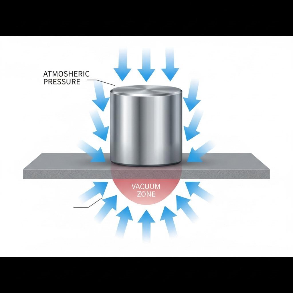
Understanding the Vacuum Effect in Punch Retraction
Imagine pressing a suction cup against a smooth surface. When you try to pull it away, atmospheric pressure fights to keep it attached. The same principle applies when your punch retracts from a freshly sheared slug.
Here's what happens in milliseconds during each stroke:
- The punch shears through the material and bottoms out against the slug
- The flat punch face creates an airtight seal with the slug's smooth surface
- As the punch begins its return stroke, it attempts to separate from the slug
- A partial vacuum forms in the gap between punch face and slug
- Atmospheric pressure (approximately 14.7 psi at sea level) pushes down on the slug from above
- With no air underneath to equalize pressure, the slug pulls horizontally—or rather, vertically—with the punch
The faster your punch retracts, the more pronounced this vacuum effect becomes. Think of it like pulling a slug pull shot in a hurry—speed amplifies the suction. A 2 slug mass pulls horizontally against atmospheric forces that seem insignificant until you calculate them across the entire contact area. Even modest vacuum levels across a half-inch diameter punch face generate several pounds of holding force.
How Oil Films Create Adhesive Forces
Lubricants are essential for reducing friction and extending tool life, but they introduce another adhesion mechanism that compounds your slug pulling problem.
When lubricant coats both the punch face and workpiece material, it creates a thin oil film trapped between surfaces during the punching operation. This film behaves differently than you might expect:
- Surface tension bonds: Oil molecules attract both the punch face and slug surface simultaneously, creating a liquid bridge that resists separation
- Viscous drag: Thicker lubricants require more force to shear apart, increasing the pull on the slug during retraction
- Capillary action: Oil wicks into microscopic surface irregularities, increasing the effective contact area and adhesion strength
The slug pulls skin off the die opening metaphorically speaking—the oil film acts like an adhesive layer that refuses to let go. Heavier lubricants applied generously create stronger bonds than light misting. Temperature also plays a role: cold lubricants are more viscous and adhesive, while warm oils flow more freely and release more easily.
Magnetic Attraction in Ferrous Materials
Working with steel or iron-based alloys? You're fighting physics on yet another front. Magnetic attraction adds an invisible force that pulls ferrous slugs back toward your punch.
Two magnetic phenomena contribute to this problem:
- Residual magnetism: Tool steel punches can become magnetized over time through repeated mechanical stress, exposure to magnetic chucks, or proximity to electrical equipment. This permanent magnetization attracts every ferrous slug you punch.
- Induced magnetism: Even non-magnetized punches can temporarily magnetize ferrous workpieces during the shearing process. The high-pressure contact and material deformation create localized magnetic fields.
The magnetic force may seem weak compared to vacuum effects, but it's constant and cumulative. Combined with other adhesion mechanisms, it often provides just enough extra grip to prevent clean slug release.
Material Springback and Elastic Recovery
The final piece of the physics puzzle involves the slug itself fighting back through elastic recovery.
When your punch shears through sheet metal, the slug undergoes significant deformation. The material compresses slightly, and the edges deform as they're forced through the die opening. Once the shearing force releases, the slug attempts to return to its original dimensions—a phenomenon called springback.
This elastic recovery causes the slug to expand slightly, gripping the punch walls like a pressure fit. The tighter your die clearance, the more pronounced this effect becomes. Softer, more elastic materials like aluminum and copper exhibit greater springback than harder steels, making them particularly prone to this adhesion mechanism.
Understanding these four physical forces—vacuum, oil adhesion, magnetism, and springback—gives you the foundation to diagnose which mechanisms dominate in your specific operation. With this knowledge, you're ready to systematically identify your root cause and select the most effective fix.
Systematic Troubleshooting to Identify Your Slug Pulling Root Cause
Now that you understand the physics behind slug adhesion, you're probably wondering: which mechanism is causing my specific problem? Jumping straight to solutions without proper diagnosis is like throwing darts blindfolded—you might get lucky, but you'll waste time and money on fixes that don't address your actual issue.
The key to effective slug pulling prevention lies in systematic troubleshooting. Unlike software debugging where you can movie magic pull slugs for me from a pdf report, diagnosing mechanical adhesion requires hands-on inspection and logical elimination. Let's walk through a proven diagnostic process that pinpoints your root cause before you spend a dime on solutions.
Step-by-Step Diagnostic Process
Follow this numbered sequence exactly as written. Each step builds on the previous one, helping you narrow down the contributing factors systematically:
-
Examine the punch face condition: Start here because it's the most common culprit and easiest to inspect. Remove the punch and examine the face under good lighting. Look for:
- Flat, polished surfaces that maximize vacuum formation
- Wear patterns indicating uneven contact
- Chips, cracks, or damage that create irregular adhesion points
- Built-up material deposits from previous operations
-
Check die clearance relative to material thickness: Measure your actual die clearance and compare it to your material thickness. Use feeler gauges or precision measurement tools for accuracy. Ask yourself:
- Is the clearance too tight, causing excessive friction and springback?
- Is the clearance too loose, allowing slug tilting and jamming?
- Has the die worn over time, changing the original clearance?
-
Evaluate lubrication type and application: Examine your current lubrication setup critically:
- What lubricant type are you using (oil, synthetic, water-based)?
- How is it applied (flood, mist, roller, manual)?
- Is application consistent across all punching locations?
- Has the lubricant viscosity changed due to temperature or contamination?
-
Assess punch speed and stroke characteristics: Review your press settings and observe the operation:
- What is your strokes-per-minute rate?
- How fast is the punch retraction speed specifically?
- Does slug pulling occur consistently or only at certain speeds?
- Have you recently changed press settings or tooling?
-
Consider material properties and thickness: Finally, evaluate the workpiece itself:
- What material are you punching (steel, aluminum, copper, stainless)?
- What is the material thickness and hardness?
- Is the material ferrous (magnetic) or non-ferrous?
- Have you recently changed material suppliers or specifications?
For those learning how to keep slugs from pulling in turret punch press operations specifically, pay extra attention to steps 1 and 4. Turret presses often run at higher speeds with rapid tool changes, making vacuum effects and punch face condition particularly critical.
Identifying Multiple Contributing Factors
Here's what most troubleshooting guides won't tell you: slug pulling rarely stems from a single cause. In real-world operations, you're typically fighting two, three, or even four contributing factors simultaneously.
Imagine this scenario: your punch face is slightly worn (contributing factor 1), you're using a heavy-viscosity lubricant (contributing factor 2), and you're punching soft aluminum that exhibits significant springback (contributing factor 3). Each factor alone might not cause slug pulling, but together they create enough adhesion force to defeat gravity.
Use this prioritization framework when multiple factors are present:
| Priority Level | Factor Type | Why Prioritize | Action Approach |
|---|---|---|---|
| High | Punch face damage or severe wear | Damaged tooling causes unpredictable behavior and risks die damage | Address immediately—replace or refurbish punch |
| High | Die clearance outside specifications | Incorrect clearance affects part quality beyond just slug pulling | Correct before adjusting other variables |
| Medium | Lubrication issues | Easy to adjust and test without tooling changes | Experiment with different types or application rates |
| Medium | Speed and stroke settings | Quick to adjust but may affect production rates | Test slower retraction speeds if feasible |
| Lower | Material properties | Often fixed by customer specifications—limited flexibility | Adjust other factors to compensate |
When you can't determine which factor dominates, start with the easiest, lowest-cost adjustment first. Change one variable at a time and observe the results. If adjusting lubrication application reduces slug pulling frequency by 50%, you've identified a major contributor even if it doesn't eliminate the problem completely.
Document everything during your diagnostic process. Note which combinations of conditions produce slug pulling and which don't. This data becomes invaluable when discussing solutions with tooling suppliers or considering die modifications.
With your root cause identified—or your list of contributing factors prioritized—you're now equipped to select the most effective fix. The next step is understanding how die clearance optimization addresses one of the most fundamental causes of slug adhesion.

Die Clearance Optimization for Different Materials and Thicknesses
You've identified die clearance as a potential contributor to your slug pulling problem. Now comes the critical question: what clearance should you actually be running? This is where most troubleshooting guides fall short—they tell you clearance matters without explaining the specifics that make or break your slug release.
Die clearance refers to the gap between the punch and die cutting edges, typically expressed as a percentage of material thickness per side. Get this number wrong, and you're fighting physics with every stroke of your press.
How Clearance Affects Slug Release
Think of die clearance as the escape route for your slug. When the punch shears through the material, the slug needs room to separate cleanly and drop through the die opening. The clearance you set determines whether that escape happens smoothly or becomes a wrestling match.
Insufficient clearance creates a tight fit between the slug and die walls. Here's what happens mechanically:
- The slug contacts the die walls with greater friction during ejection
- Material springback causes the slug to press harder against these walls
- The increased friction holds the slug in place longer during punch retraction
- Vacuum forces have more time to establish before the slug releases
- The slug may ride back up with the punch instead of falling free
Tight clearances also generate more heat from friction, which can cause lubricant to behave unpredictably and even weld microscopic material deposits to your punch face.
Excessive clearance introduces a different problem. When the gap is too large:
- The slug tilts or cocks during the shearing process
- Tilted slugs jam against die walls at awkward angles
- Greater material rollover and burr formation occur
- The slug may wedge itself between the punch and die wall
- Unpredictable slug behavior makes consistent ejection impossible
The sweet spot lies between these extremes—enough clearance for clean separation, but not so much that the slug loses its orientation during ejection.
Material-Specific Clearance Considerations
Different materials demand different clearance approaches. Softer materials behave fundamentally differently than harder ones during the shearing and ejection process. Aluminum, for example, is more ductile and exhibits greater elastic springback than carbon steel. This means aluminum slugs expand more after shearing, requiring additional clearance to prevent binding.
Stainless steel presents the opposite challenge. Its work-hardening characteristics and higher strength mean it shears more cleanly but can be more abrasive on tooling. Clearances that work perfectly for mild steel often prove inadequate for stainless applications.
Copper and brass alloys fall somewhere in between. Their excellent ductility makes them prone to burring with excessive clearance, but their relatively soft nature means they don't bind as aggressively as harder materials with tight clearances.
Material thickness adds another variable to your calculations. Thinner materials generally tolerate tighter clearance percentages because there's less material to spring back. As thickness increases, you typically need to increase your clearance percentage to accommodate greater elastic recovery and ensure reliable slug release.
The following table provides general clearance considerations by material type and thickness range. Note that these are starting points for troubleshooting—always verify specific percentages against your tooling manufacturer's recommendations for your exact application:
| Material Type | Thin Gauge (Under 1mm) | Medium Gauge (1-3mm) | Heavy Gauge (Over 3mm) | Slug Pulling Tendency |
|---|---|---|---|---|
| Aluminum Alloys | Moderate clearance needed | Increased clearance required | Maximum clearance range | High—significant springback |
| Carbon Steel | Tighter clearance acceptable | Standard clearance range | Moderate increase needed | Medium—balanced properties |
| Stainless Steel | Tighter clearance typical | Slightly increased clearance | Moderate clearance needed | Medium—work hardening factor |
| Copper/Brass | Moderate clearance needed | Standard to increased range | Increased clearance required | Medium-High—ductile behavior |
When adjusting clearance to address slug pulling, make incremental changes rather than dramatic shifts. Increase clearance in small steps and test after each adjustment. Document which clearance settings produce clean slug release versus which cause pulling or jamming.
Keep in mind that clearance optimization often works in conjunction with other fixes. You might find that slightly opening your clearance reduces slug pulling frequency, while combining that adjustment with lubrication changes eliminates the problem entirely. The diagnostic work you completed earlier helps you understand which combination of adjustments will prove most effective.
If your current tooling doesn't allow clearance adjustment, or if optimal clearance for slug release conflicts with part quality requirements, you'll need to explore alternative solutions. Punch geometry modifications offer another powerful approach to breaking the adhesion cycle—and that's exactly where we're headed next.
Punch Geometry Variations That Prevent Slug Adhesion
You've optimized your die clearance, but slugs are still riding back up with your punch. What's next? The answer often lies in the punch face itself—specifically, its geometry. The shape of your punch face determines how much vacuum forms, how cleanly the slug separates, and whether gravity can do its job during retraction.
Most stamping operations default to standard flat-face punches because they're simple and versatile. However, flat faces create the maximum vacuum effect we discussed earlier. Changing your punch geometry is like switching from a suction cup to a colander—you're fundamentally altering the physics of adhesion.
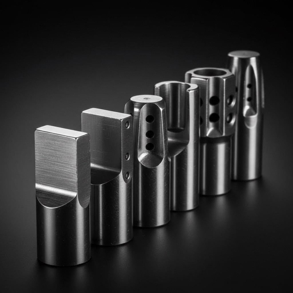
Flat vs. Concave Punch Face Designs
Flat punch faces seem logical—they provide maximum contact with the material and create clean shear lines. But that full contact is exactly what causes problems during retraction.
When a flat punch face separates from a slug, there's no path for air to enter the gap. The result? A partial vacuum that fights against slug release. The larger your punch diameter, the greater the surface area affected, and the stronger the suction force becomes.
Concave punch faces solve this problem elegantly. By machining a slight dish or depression into the punch face, you create an air pocket that prevents full surface contact. Here's how it works:
- The outer edge of the punch contacts the slug and performs the shearing action
- The recessed center never touches the slug surface
- When the punch retracts, air immediately fills the concave space
- No vacuum forms because there's no airtight seal to begin with
- The slug releases cleanly under its own weight
The depth of the concave recess matters. Too shallow, and you still get partial vacuum formation. Too deep, and you risk affecting the shearing action or weakening the punch tip. Most manufacturers recommend a recess depth between 0.5mm and 1.5mm depending on punch diameter and material being cut.
Vented punch designs take a different approach to the same problem. Instead of a concave face, these punches feature small holes or channels that allow air to pass through the punch body. During retraction, atmospheric pressure equalizes instantly through these vents, eliminating vacuum formation entirely.
Vented punches work exceptionally well but require more complex manufacturing and maintenance. The vent holes can become clogged with lubricant or debris over time, reducing their effectiveness. Regular cleaning is essential to maintain their anti-slug-pulling performance.
When to Specify Shear-Angle Punches
Shear-angle punches feature an angled cutting face rather than a flat or concave profile. This geometry reduces the cutting force required by concentrating pressure on a smaller contact area—similar to how scissors cut more easily than a guillotine.
For slug pulling considerations, shear-angle punches present a trade-off:
- Advantage: The angled face contacts the slug progressively rather than all at once, reducing the potential for full-surface vacuum formation
- Advantage: Lower cutting forces mean less material compression and potentially less springback
- Consideration: The slug itself becomes slightly curved or dished, which can affect how it releases and falls
- Consideration: Asymmetric forces may cause the slug to eject at an angle rather than dropping straight down
Shear-angle punches work best for larger holes in thicker materials where cutting force reduction provides significant benefits. For small-diameter punching in thin materials, the slug pulling benefits may not outweigh the complexity of managing angled slug ejection.
Whisper-tip and specialty designs represent the cutting edge of anti-slug-pulling technology. These proprietary punch geometries combine multiple features—slight concavity, micro-texturing, and optimized edge profiles—to maximize slug release. While more expensive than standard punches, they often prove cost-effective in high-volume operations where even small improvements in slug release translate to significant productivity gains.
The following table compares common punch geometries and their effects on slug behavior:
| Geometry Type | Vacuum Effect | Best Applications | Slug Pulling Tendency |
|---|---|---|---|
| Flat Face | Maximum—full surface contact creates strong suction | General purpose where slug pulling isn't problematic | High |
| Concave/Dished | Minimal—air pocket prevents vacuum formation | Medium to large diameter holes; oily materials | Low |
| Vented | None—air passes through punch body | High-speed operations; sticky materials; large diameters | Very Low |
| Shear Angle | Reduced—progressive contact limits vacuum area | Thick materials; force-sensitive applications | Medium-Low |
| Whisper-Tip/Specialty | Minimal—engineered surface features break vacuum | High-volume production; critical applications | Very Low |
Selecting the right punch geometry depends on balancing slug pulling prevention against other factors like punch life, part quality requirements, and cost. A lap slug pull shot approach—trying different geometries systematically—often reveals the ideal solution for your specific application. Consider starting with concave designs for general improvements, then advancing to vented or specialty punches if problems persist.
Remember that punch geometry works alongside the other factors you've already evaluated. The ideal slug gun trigger pull weight for hunters requires matching the right trigger to the right application—similarly, matching punch geometry to your specific material, thickness, and production requirements delivers the best results. With geometry optimized, you're ready to explore the full range of prevention methods and compare their effectiveness for your operation.
Comparing Prevention Methods From Quick Fixes to Permanent Solutions
You've diagnosed your slug pulling root cause and understand the physics at play. Now comes the practical question: which fix should you implement? With dozens of prevention methods available—from simple lubrication tweaks to complete die redesigns—choosing the right approach requires balancing effectiveness against cost, implementation time, and your specific production constraints.
Think of slug pulling solutions like medical treatments. Some are quick remedies that provide immediate relief but may need repeated application. Others are surgical interventions that permanently eliminate the problem but require more upfront investment. The best choice depends on your symptoms, budget, and long-term goals.
Let's organize the available solutions into four categories and compare their relative merits systematically.
Quick Fixes for Immediate Production Relief
When slugs are pulling right now and production deadlines are breathing down your neck, you need solutions you can implement in minutes or hours—not days or weeks. These temporary fixes won't permanently solve your problem, but they'll get your line running while you plan a more comprehensive solution.
Operational Adjustments
The fastest fixes involve changing how you run your existing equipment rather than modifying any hardware:
- Reduce retraction speed: Slowing your punch retraction gives slugs more time to separate before vacuum forces peak. Many presses allow speed adjustments without stopping production.
- Modify lubrication application: Switch to a lighter-viscosity lubricant or reduce application volume. Less oil means weaker adhesive bonds between punch face and slug.
- Adjust stroke depth: Ensure your punch is penetrating far enough to push the slug completely clear of the die opening before retraction begins.
- Change running temperature: If possible, allow the tooling to warm up before high-speed operation. Warmer lubricants are less viscous and release more easily.
These adjustments cost nothing to implement but may affect your production rate or part quality. Consider them stopgap measures while planning permanent solutions.
Mechanical Quick-Add Solutions
Several mechanical devices can be added to existing tooling without major modifications:
- Spring-loaded ejector pins: These small springs mount in the punch face and physically push the slug away during retraction. Installation typically requires only drilling and tapping the punch—a thumb slug puller approach that's simple but effective.
- Magnetic slug retainers: For non-ferrous materials, adding magnets to the die can hold ferrous slugs in place during punch retraction. This works only when punching non-magnetic materials through magnetic dies.
- Urethane ejector inserts: Soft urethane plugs compress during the punch stroke, then expand to push the slug free during retraction. They're inexpensive and easy to replace when worn.
The thumb slug puller techline of products represents one example of aftermarket ejection solutions. These devices provide immediate relief but require ongoing maintenance and eventual replacement.
Air Blast Systems
Compressed air offers a powerful slug ejection assist that's relatively easy to implement:
- Timed air blasts fire during punch retraction to break vacuum and push slugs clear
- Continuous low-pressure air flow prevents vacuum formation entirely
- Directional nozzles can guide slugs toward scrap chutes
Air blast systems require compressed air infrastructure and may add operating costs, but they're highly effective for stubborn slug pulling problems. They work especially well in combination with other methods.
Long-Term Engineering Solutions
Quick fixes keep you running, but permanent solutions eliminate recurring problems and their associated maintenance burden. These approaches require more upfront investment but deliver lasting results.
Punch Replacement and Modification
Replacing standard flat-face punches with anti-slug-pulling geometries addresses the root cause directly:
- Concave or vented punches: As discussed previously, these geometries prevent vacuum formation by design. The investment pays off through eliminated downtime and reduced maintenance.
- Coated punches: Surface treatments like TiN or specialized low-friction coatings reduce adhesion forces permanently. We'll cover these in detail in the next section.
- Custom-engineered punch profiles: For persistent problems, tooling manufacturers can design application-specific punch geometries that optimize slug release for your exact material and thickness combination.
Die Design Modifications
Sometimes the punch isn't the problem—the die needs attention:
- Slug retention features: Adding chamfers, reliefs, or textured surfaces inside the die opening helps grip the slug during punch retraction, preventing it from following the punch back up.
- Positive knockout systems: Mechanical or pneumatic systems that physically eject slugs through the die with each stroke. These guarantee slug removal regardless of adhesion forces.
- Optimized die clearance: Recutting or replacing dies with proper clearance for your material eliminates the springback and friction problems that contribute to slug pulling.
Complete Tooling Redesign
For severe or complex slug pulling problems, redesigning the entire tooling setup may prove most cost-effective in the long run. This approach considers slug ejection from the initial design phase rather than treating it as an afterthought.
Understanding how to pull trigger on slug gun success requires matching your solution to your specific situation—just as hunters select different approaches for different game. The following comparison table helps you evaluate options across key decision factors:
| Prevention Method | Effectiveness | Implementation Cost | Best Use Cases |
|---|---|---|---|
| Speed/stroke adjustments | Low to Medium | Low (no cost) | Immediate relief; testing root causes |
| Lubrication modifications | Medium | Low | Oil film adhesion problems; quick testing |
| Spring-loaded ejector pins | Medium to High | Low to Medium | Retrofit existing punches; moderate production volumes |
| Urethane ejector inserts | Medium | Low | Soft materials; lower production volumes |
| Air blast systems | High | Medium | High-speed operations; multiple punch stations |
| Concave/vented punch replacement | High | Medium | Vacuum-dominated problems; new tooling purchases |
| Surface coatings (TiN, TiCN, etc.) | Medium to High | Medium | Adhesion problems; extending punch life simultaneously |
| Die slug retention features | High | Medium to High | Existing die modification; persistent problems |
| Positive knockout systems | Very High | High | Critical applications; zero-tolerance for slug pulling |
| Complete tooling redesign | Very High | High | New programs; chronic unresolved problems |
Economic Considerations for Solution Selection
Choosing between quick fixes and permanent solutions involves weighing several economic factors beyond just the upfront cost:
- Downtime costs: How much does each slug pulling incident cost in lost production? High downtime costs justify more expensive permanent solutions.
- Maintenance burden: Quick fixes require ongoing attention. Factor in labor costs for repeated adjustments and replacements.
- Part quality impact: If slug pulling causes scrap or rework, include those costs in your analysis.
- Safety considerations: Unpredictable slug ejection creates operator hazards. Some solutions may be justified purely on safety grounds.
- Production volume: High-volume operations amortize permanent solution costs over more parts, improving their economic case.
Much like the complexity of video game mechanics where players must pull sea slug out of little sister Bioshock to progress, solving slug pulling often requires understanding underlying systems before taking action. And just as gamers searching for pull sea slug out of little sister Bioshock how discover multiple valid approaches, stamping engineers find that several prevention methods can work—the key is matching the method to your specific situation.
The most effective approach often combines multiple solutions. You might implement a quick lubrication adjustment for immediate relief while ordering replacement punches with anti-slug-pulling geometry for permanent resolution. This layered strategy keeps production running while addressing the root cause systematically.
With your prevention method selected, you may be wondering about surface treatments and coatings—another powerful tool in the anti-slug-pulling arsenal. Let's examine how these technologies reduce adhesion at the molecular level.
Surface Treatments and Coatings for Anti-Slug-Pulling Performance
You've selected your punch geometry and prevention method strategy. Now it's time to explore a solution that works at the molecular level—surface treatments and coatings that fundamentally change how your punch face interacts with slugs. These technologies don't just mask the problem; they alter the adhesion physics we discussed earlier.
Think of coatings like a non-stick pan in your kitchen. The same food that stubbornly adheres to bare metal slides right off a coated surface. Applied to punches, the right coating can dramatically reduce the vacuum and oil film adhesion forces that cause slugs to ride back up during retraction.
Coating Technologies That Reduce Slug Adhesion
Modern coating technologies offer several options for reducing slug adhesion, each with distinct properties suited to different applications. Understanding these differences helps you select the right coating for your specific material, production volume, and budget constraints.
Titanium Nitride (TiN) represents the most common and cost-effective coating option. Its characteristic gold color makes it easy to identify, and its properties deliver meaningful slug pulling prevention:
- Creates a hard, low-friction surface that reduces oil film adhesion
- Decreases surface energy, making it harder for slugs to bond with the punch face
- Extends punch life by 3-5 times compared to uncoated tools
- Works well with ferrous and non-ferrous materials alike
- Most economical option for general slug pulling prevention
Titanium Carbonitride (TiCN) offers enhanced performance over standard TiN. Its gray-blue appearance indicates a harder, more wear-resistant surface:
- Higher hardness than TiN provides better abrasion resistance
- Lower coefficient of friction reduces both cutting forces and adhesion
- Excellent performance with abrasive materials like stainless steel
- Better thermal stability for high-speed operations
- Moderate cost increase over TiN with significant performance gains
Titanium Aluminum Nitride (TiAlN) excels in high-temperature applications where other coatings might break down:
- Superior heat resistance maintains coating integrity during aggressive punching
- Oxidation resistance prevents coating degradation in demanding environments
- Excellent for high-speed, high-volume production runs
- Works particularly well with harder materials that generate more heat
- Higher cost justified by extended service life in demanding applications
Diamond-Like Carbon (DLC) coatings represent the premium tier for slug pulling prevention:
- Extremely low friction coefficient—among the lowest of any coating technology
- Exceptional release properties that virtually eliminate adhesion
- Excellent performance with aluminum and other gummy materials
- Highest cost but delivers superior results for critical applications
- May require specialized application and maintenance procedures
When selecting a coating, consider not just slug pulling prevention but also your material, production volume, and how the coating interacts with your lubrication system.
Surface Texturing Strategies for Punch Faces
Coatings aren't your only surface modification option. Strategic texturing of the punch face can break vacuum formation and reduce contact area without adding any coating material.
Micro-texturing approaches create tiny patterns on the punch face that prevent full surface contact:
- Cross-hatch patterns: Fine grooves machined in intersecting directions create air channels that break vacuum formation
- Dimple patterns: Small spherical depressions reduce contact area while maintaining punch face integrity
- Laser-etched textures: Precise patterns applied via laser create consistent micro-channels for air ingress
These textures work by preventing the airtight seal that causes vacuum adhesion. Air can flow through the channels or around the raised areas, equalizing pressure before suction forces build.
Polishing considerations deserve careful thought. Conventional wisdom suggests that smoother surfaces reduce friction—but for slug pulling, the opposite can be true:
- Mirror-polished punch faces maximize surface contact and vacuum formation
- Slightly textured surfaces actually release slugs more easily than perfectly smooth ones
- The ideal finish balances enough roughness to break vacuum while remaining smooth enough to prevent material buildup
However, polishing does help when combined with coatings. A polished surface under a low-friction coating provides the best of both worlds—the coating prevents adhesion while the smooth substrate allows uniform coating application.
Coating and Lubrication Interactions
Your punch surface and lubrication system work together—or against each other—depending on how well they're matched. Coated punches interact with lubricants differently than bare tool steel:
- Low-friction coatings may require less lubricant, reducing oil film adhesion problems
- Some coatings are hydrophobic (water-repelling), affecting water-based lubricant performance
- Heavy lubricants can mask coating benefits by creating thick adhesive films regardless of surface properties
- Matching lubricant viscosity to coating type optimizes both cutting performance and slug release
When implementing coatings for slug pulling prevention, consider adjusting your lubrication simultaneously. A coated punch with optimized lubrication often outperforms either solution alone.
Surface treatments provide a powerful tool in your anti-slug-pulling arsenal, but they work best as part of a comprehensive approach. Combining the right coating with proper punch geometry, optimized clearance, and appropriate lubrication delivers results that none of these solutions achieves independently. With surface treatment options understood, you're ready to consider how proactive die design can prevent slug pulling before it ever becomes a problem.

Proactive Die Design Strategies to Eliminate Slug Pulling
What if you could eliminate slug pulling before your die ever runs its first production stroke? Most discussions about slug pulling causes and fixes focus on troubleshooting existing problems—adjusting clearances, changing lubricants, adding ejector pins to tooling that's already causing headaches. But the most effective solution often lies in prevention during the design phase itself.
Designing out slug pulling from the start costs significantly less than retrofitting solutions later. When you specify anti-slug-pulling features during initial die design, those features integrate seamlessly into the tooling rather than being bolted on as afterthoughts. The result? Dies that run cleanly from day one, with fewer surprises and lower lifetime maintenance costs.
Designing Out Slug Pulling From the Start
Prevention-oriented die design requires considering slug ejection as a primary design criterion—not a secondary concern addressed only when problems arise. Here's how to specify anti-slug-pulling features during initial tooling development:
Proper Clearance Calculations
During the design phase, engineers can optimize die clearance based on the specific material, thickness, and production requirements rather than accepting generic defaults. This proactive approach involves:
- Analyzing material properties including hardness, ductility, and springback characteristics
- Calculating optimal clearance percentages for the specific material-thickness combination
- Building in adjustability where multiple materials or thicknesses will be processed
- Documenting clearance specifications for future maintenance and replacement
Punch Geometry Selection
Rather than defaulting to flat-face punches and addressing problems later, specify anti-slug-pulling geometries from the initial design:
- Specify concave or vented punch faces for hole sizes and materials prone to adhesion
- Include ejector pin provisions in punch designs where mechanical ejection may be needed
- Select appropriate coatings during punch specification rather than adding them after problems emerge
- Consider whisper-tip or specialty designs for critical applications
Ejection System Integration
Designing ejection systems into the die from the beginning provides several advantages:
- Spring-loaded ejectors can be properly sized and positioned for optimal performance
- Air blast provisions can be integrated into the die structure rather than externally mounted
- Positive knockout systems can be engineered into the stripper plate design
- Slug chute angles and clearances can be optimized for reliable slug evacuation
Material Considerations
Experienced die designers account for how different workpiece materials behave during punching:
- Aluminum and soft alloys require additional ejection provisions due to high springback
- Oily or pre-lubricated materials need surface treatments or geometries that defeat adhesion
- Ferrous materials may require demagnetization provisions in the production process
- Material thickness variations across production runs influence clearance and geometry decisions
The Role of Simulation in Prevention
Modern CAE (Computer-Aided Engineering) simulation has transformed how engineers approach die design. Rather than building tooling and discovering problems during tryout, simulation predicts slug behavior before cutting metal.
Advanced simulation capabilities include:
- Material flow analysis: Predicting how specific materials deform during shearing and whether springback will contribute to slug retention
- Clearance optimization: Testing multiple clearance values virtually to identify the sweet spot for clean slug release
- Ejection force calculations: Determining whether gravity alone will eject slugs or whether mechanical assistance is required
- Vacuum effect modeling: Analyzing punch face geometry and predicting adhesion forces during retraction
Simulation allows engineers to test design modifications virtually—iterating through punch geometries, clearance values, and ejection approaches without building physical prototypes. This accelerates the design process while reducing the risk of slug pulling problems appearing during production.
Working with die manufacturers who leverage CAE simulation provides significant advantages. Companies like Shaoyi, with IATF 16949 certification and advanced simulation capabilities, can predict and prevent defects including slug pulling before tooling fabrication begins. Their engineering team uses simulation to optimize clearances, validate punch geometries, and ensure ejection systems perform as designed—delivering a 93% first-pass approval rate that reflects this proactive approach.
The value of this prevention-oriented methodology becomes clear when you consider the alternatives. Troubleshooting slug pulling after tooling is built requires:
- Production interruptions during diagnosis and modification
- Additional tooling costs for replacement punches or die modifications
- Engineering time spent solving problems rather than adding value
- Quality risks as modified tooling may introduce new issues
Prevention during design eliminates these costs entirely. When you partner with experienced die manufacturers from the beginning—those who understand slug pulling prevention as a design criterion—you're investing in tooling that works correctly from the first stroke.
Rapid prototyping capabilities further enhance this proactive approach. When simulation results need physical validation, manufacturers offering quick-turn prototypes (in as little as 5 days for some applications) can verify anti-slug-pulling features before committing to full production tooling. This iterative approach—simulate, prototype, validate—ensures your production dies deliver the clean slug ejection you need.
Whether you're specifying new dies for an upcoming program or planning replacement tooling for existing applications, consider making slug pulling prevention a primary design requirement. The upfront engineering investment pays dividends throughout the die's production life—fewer interruptions, less maintenance, and more consistent part quality.
Of course, even the best-designed dies operate within a larger production system. Understanding how slug pulling affects overall die performance and part quality helps you appreciate why this proactive approach matters so much.
The Ripple Effects of Slug Pulling on Die Performance and Part Quality
Slug pulling rarely exists in isolation. When you're focused on stopping that stubborn slug from riding back up with your punch, it's easy to miss the bigger picture—the cascading damage rippling through your entire operation. Understanding these connections transforms slug pulling from a nuisance into a priority that demands immediate attention.
Think of slug pulling like a small crack in your car's windshield. Left unaddressed, that crack spreads. Road vibration, temperature changes, and time work together until suddenly you're facing a complete windshield replacement instead of a simple repair. Slug pulling works the same way in your stamping operation—a problem that compounds into multiple expensive failures.
How Slug Pulling Accelerates Die Wear
Every time a slug rides back up with your punch, something has to give. That slug doesn't simply disappear—it gets crushed, deformed, or slammed between tooling components that were never designed to handle it.
Here's the wear progression you're likely experiencing:
Impact damage to punch faces: When a pulled slug gets trapped between the punch and workpiece during the next stroke, the punch face absorbs tremendous impact forces. These repeated micro-collisions create dents, chips, and surface irregularities that—ironically—make future slug pulling even more likely. Damaged punch faces create inconsistent contact, leading to unpredictable vacuum formation and adhesion.
Die cutting edge deterioration: Slugs that don't clear the die opening properly can jam against cutting edges during subsequent strokes. Each jam forces material against precision-ground surfaces, accelerating edge wear and dulling. What should be a sharp, clean shearing action becomes a crushing, tearing operation that produces poor-quality cuts.
Stripper plate damage: Pulled slugs often end up trapped between the stripper plate and workpiece material. The stripper plate, designed for smooth material control, now absorbs impact forces it wasn't engineered to handle. Over time, this abuse leads to stripper wear, inconsistent material hold-down, and secondary quality problems.
The compounding nature of this wear pattern means your tooling degradation accelerates over time. A punch that should last hundreds of thousands of strokes may fail in a fraction of that life when slug pulling goes unaddressed.
Quality and Safety Implications
Beyond tooling wear, slug pulling creates immediate quality problems that can slip past inspection and reach your customers.
Part defects from pulled slugs include:
- Surface impressions: Slugs trapped under the workpiece create dents, dings, and witness marks on finished parts
- Burr formation: Disrupted shearing action from slug interference produces excessive burrs that require secondary operations to remove
- Dimensional inconsistencies: Damaged cutting edges produce holes with inconsistent diameters, out-of-tolerance features, and edge quality variations
- Cosmetic defects: Scratches from slug contact ruin surface finishes on visible parts, increasing scrap rates
- Material contamination: Slug fragments can embed in soft materials like aluminum, creating hidden defects
These quality issues often appear intermittently, making them difficult to correlate with the root cause. You might scrap parts for "random" surface defects without realizing that occasional slug pulling events are responsible.
Safety hazards represent perhaps the most serious concern. When slugs don't fall predictably through the die opening, they can:
- Eject sideways at high velocity, striking operators or bystanders
- Accumulate in unexpected locations, creating slip hazards or interfering with other equipment
- Cause sudden die crashes that startle operators and may lead to reactive injuries
- Create unpredictable press behavior that makes safe operation difficult
Operators working around dies with slug pulling problems often develop workarounds—reaching into danger zones to clear jams, running at reduced speeds, or ignoring warning signs. These adaptive behaviors increase injury risk while masking the underlying problem.
The Cascading Effects on Production Operations
When you step back and view slug pulling holistically, the full scope of its impact becomes clear. Unresolved slug pulling creates a cascade of problems that extend far beyond the immediate tooling station:
- Increased unplanned downtime: Each slug pulling incident requires stopping production, clearing the problem, and inspecting for damage before resuming
- Elevated maintenance costs: Accelerated tooling wear demands more frequent sharpening, refurbishment, and replacement
- Higher scrap rates: Quality defects from slug interference increase material waste and reduce yield
- Secondary operation costs: Burrs and surface defects require additional processing to meet specifications
- Reduced operator confidence: Unpredictable die behavior creates stress and may lead to excessive caution that slows production
- Customer quality complaints: Defects that escape inspection damage your reputation and may result in costly returns or claims
- Compressed tool life: Tooling that should last months may require replacement in weeks when slug pulling accelerates wear
- Engineering distraction: Problem-solving time spent on slug pulling isn't available for process improvement or new program development
The financial impact of these cascading effects typically far exceeds the cost of implementing proper slug pulling prevention. When you calculate the true cost—including downtime, scrap, maintenance, and quality risks—investing in solutions becomes an obvious business decision rather than an optional improvement.
Addressing slug pulling isn't just about stopping one annoying problem. It's about protecting your tooling investment, ensuring consistent part quality, maintaining operator safety, and optimizing your overall production efficiency. The solutions we've covered throughout this guide—from clearance optimization and punch geometry changes to surface treatments and proactive die design—deliver benefits that extend well beyond simply keeping slugs where they belong.
By treating slug pulling as a systemic issue rather than an isolated nuisance, you position your operation for sustained success. Cleaner slug ejection means longer tool life, fewer interruptions, better parts, and safer operations. That's not just fixing a problem—that's transforming your stamping performance.
Frequently Asked Questions About Slug Pulling
1. What is slug pulling?
Slug pulling occurs when punched-out material (the slug) adheres to the punch face and travels back up through the die during the return stroke instead of falling cleanly through the die opening. This phenomenon happens due to vacuum formation, oil film adhesion, magnetic attraction in ferrous materials, or material springback. When slugs are pulled back into the work zone, they cause die damage, part quality defects, production downtime, and safety hazards for operators.
2. What causes an infestation of slug pulling problems?
Multiple factors contribute to persistent slug pulling: trapped air creating vacuum pockets between the punch face and slug, large or improper cutting clearances, extremely fast piercing operations, sticky or heavy-viscosity lubricants, improperly demagnetized punches attracting ferrous slugs, and fatigued or insufficient spring ejectors. Material properties like thickness, hardness, and ductility also play significant roles. Often, two or more factors work together, requiring systematic diagnosis to identify all contributing causes.
3. How can I prevent slug pulling with the right die clearance?
Optimal die clearance varies by material type and thickness. Insufficient clearance creates tighter slug-to-die-wall contact, increasing friction and springback that holds slugs against the punch. Excessive clearance causes slug tilting and jamming. Softer materials like aluminum require increased clearance to accommodate greater elastic springback, while harder materials like stainless steel typically tolerate tighter clearances. Always verify specific percentages against your tooling manufacturer's specifications and make incremental adjustments when troubleshooting.
4. What punch geometry prevents slug adhesion most effectively?
Concave and vented punch designs most effectively prevent slug adhesion by eliminating vacuum formation. Concave punch faces create an air pocket that prevents full surface contact, while vented punches feature holes allowing air to pass through during retraction. Flat-face punches create maximum vacuum effect and have high slug pulling tendency. Shear-angle punches reduce the effect moderately through progressive contact. Specialty whisper-tip designs combine multiple features for optimal release in high-volume production.
5. How can simulation and proactive die design eliminate slug pulling?
Modern CAE simulation predicts slug behavior before cutting metal, allowing engineers to optimize clearances, validate punch geometries, and ensure ejection systems perform correctly during the design phase. Working with experienced die manufacturers like Shaoyi, who leverage IATF 16949 certified processes and advanced simulation capabilities, helps prevent slug pulling before tooling fabrication. This proactive approach costs significantly less than retrofitting solutions and delivers dies that run cleanly from the first production stroke.