 Small batches, high standards. Our rapid prototyping service makes validation faster and easier —

Sheet Metal Stamping Dies Exposed: From Tool Steel To ROI Secrets
What Are Sheet Metal Stamping Dies and How Do They Work
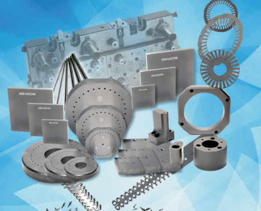
Ever wondered how manufacturers transform flat sheets of metal into precisely shaped automotive panels, appliance components, or medical devices? The answer lies in sheet metal stamping dies—specialized precision tools that have revolutionized modern manufacturing.
So, what is a stamping die exactly? In simple terms, it's a hard tool, typically consisting of a male and female pair, designed to cut, bend, shape, or form sheet metal into a desired configuration. You'll often hear professionals refer to these tools as "stamping tools" or simply "tooling." According to Stamping Simulation, these dies are frequently described as "tooling" because manufacturing a required shape typically demands multiple stamping dies working through several process steps.
What are dies used for in practice? The most prominent application remains the automotive industry, where virtually every sheet metal component—from door panels to structural brackets—originates from a die stamp process. Consumer goods manufacturers, including dishwasher and washing machine producers, represent the second-largest user base, followed by the building and medical industries.
The Punch and Die Relationship Explained
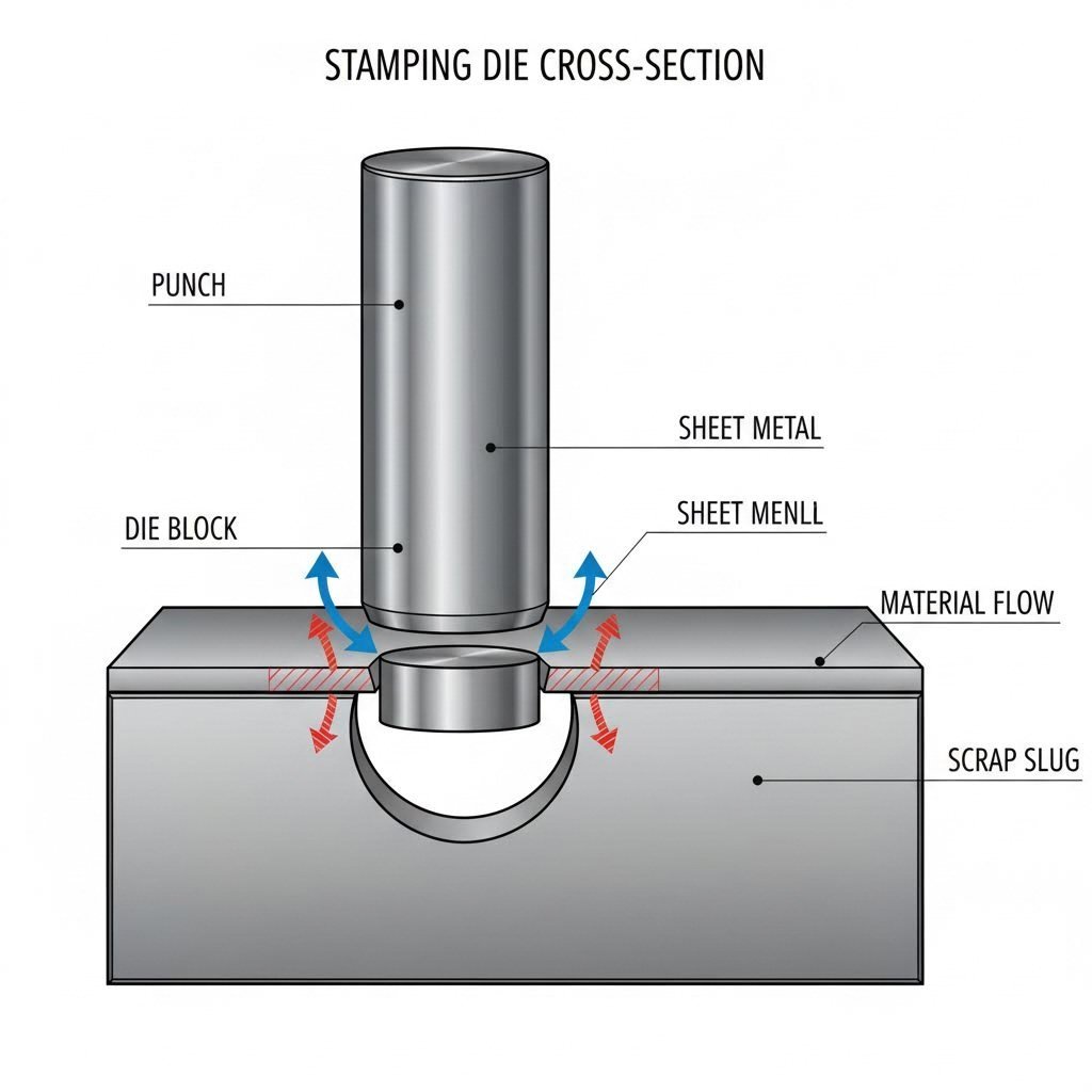
Imagine a cookie cutter pressing through dough—that's the basic principle behind how stamping dies work, though with far greater precision and force. The system relies on two essential components working in perfect harmony:
- The punch (male component): This upper tool descends with controlled force, pushing material into or through the lower component
- The die (female component): This lower tool contains the cavity or opening that receives the material and defines the final shape
When you place a flat metal sheet between these components and the press applies force, the material yields and flows according to the die's geometry. The clearance between punch and die—measured in thousandths of an inch—determines edge quality, burr formation, and overall part precision. A die for press applications must maintain exact tolerances throughout millions of cycles to produce consistent results.
Why Precision Tooling Matters in High-Volume Production
Here's where things get interesting. What is metal stamping's real advantage over other forming methods? Speed and consistency. Well-designed stamping dies can produce parts at rates exceeding 60 pieces per minute, though 20 parts per minute represents a more common production speed.
This capability becomes critical when you're manufacturing 50,000 or more parts annually. At these volumes, even minor variations between components create significant quality issues downstream. Precision tooling eliminates this concern by delivering identical parts stroke after stroke.
However, this performance comes with substantial investment. According to industry data, tooling costs typically range from USD $100,000 to $500,000, depending on complexity. This investment makes what is stamping technology suitable primarily for high-volume applications where per-part costs decrease dramatically over extended production runs.
The engineering considerations separating basic dies from precision tooling include material selection, surface treatments, clearance calculations, and maintenance protocols—topics we'll explore in detail throughout this guide. Understanding these fundamentals helps you make informed decisions about tooling investments that directly impact your manufacturing success.
Types of Stamping Dies and When to Use Each Configuration
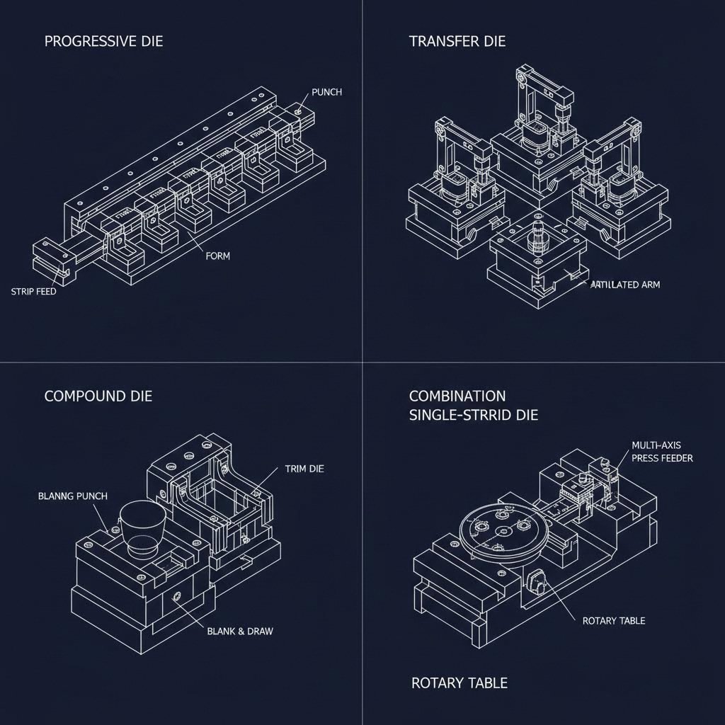
Now that you understand how stamping dies work, the next logical question becomes: which type of stamping die fits your specific application? The answer depends on your part complexity, production volume, and budget constraints. Let's break down the four primary types of stamping dies and explore when each configuration makes the most sense.
When it comes to dies and stamping operations, manufacturers typically choose from progressive dies, transfer dies, compound dies, or combination dies. Each offers distinct advantages depending on your production requirements. The table below provides a quick comparison to help you navigate these options:
| Die Type | Typical Applications | Production Volume | Complexity Level | Relative Cost | Key Advantages |
|---|---|---|---|---|---|
| Progressive Dies | Automotive brackets, clips, electronic components | High volume (100,000+ parts) | Medium to High | High initial investment | Maximum speed, excellent uniformity |
| Transfer Dies | Large automotive panels, aerospace assemblies | Medium to High volume | High | Higher operational costs | Handles large, complex parts |
| Compound Dies | Flat precision parts, washers, simple shapes | Low to Medium volume | Low to Medium | Moderate | Multiple operations in single stroke |
| Combination Dies | Parts requiring cutting and forming together | Medium volume | Medium | Moderate to High | Versatility in operation types |
Progressive Dies for High-Speed Production
Imagine an assembly line condensed into a single tool—that's essentially what progressive dies deliver. These metal stamping dies consist of multiple stations arranged in sequence, with each station performing a specific operation as the metal strip advances through the press.
According to Durex Inc., progressive dies are capable of producing large volumes of parts quickly while ensuring uniformity across all produced components. This makes them the workhorse of high-volume manufacturing, particularly in industries demanding millions of identical parts.
Key selection criteria for progressive dies:
- Annual production exceeds 100,000 parts
- Part size remains small to medium
- Design allows continuous strip feeding
- Tolerance requirements demand consistency across extended runs
- Budget accommodates higher upfront tooling investment
The variety die and stamping options available in progressive configurations make them particularly attractive for automotive manufacturers producing brackets, clips, and electronic components where speed and repeatability matter most.
Choosing Between Transfer and Compound Die Configurations
What happens when your parts are too large or complex for progressive dies? That's where transfer die configurations enter the picture. Unlike progressive dies that keep parts attached to a strip, transfer dies mechanically move individual workpieces between stations.
As noted by Worthy Hardware, transfer die stamping allows more flexibility in part handling and orientation, making it suitable for intricate designs and shapes. This method can incorporate various operations such as punching, bending, drawing, and trimming in a single production cycle.
Key selection criteria for transfer dies:
- Part dimensions exceed progressive die limitations
- Complex geometries require varied orientations during forming
- Assembly complexity demands multiple sequential operations
- Applications include aerospace or heavy machinery components
Compound dies take a different approach entirely. Rather than moving parts between stations, these forming dies perform multiple operations simultaneously in a single stroke. Think of stamping and die cutting happening at the exact same moment—cutting, bending, and embossing all completed before the press returns to its starting position.
Key selection criteria for compound dies:
- Part geometry remains relatively simple and flat
- Production volumes fall in the low to medium range
- Precision requirements are critical
- Material efficiency matters (minimal scrap)
- Budget constraints favor lower tooling investment
Combination dies bridge the gap between these configurations by blending cutting and forming operations within a single die set. They're particularly useful when your part requires both blanking and drawing operations but doesn't justify the investment in progressive tooling.
Matching Die Type to Your Manufacturing Requirements
Selecting the right stamping die ultimately comes down to balancing three factors: part complexity, production volume, and cost efficiency. Here's a practical framework to guide your decision:
- For high-volume, smaller parts: Progressive dies deliver the lowest per-part cost despite higher initial investment
- For large, complex assemblies: Transfer dies offer the flexibility and precision these applications demand
- For precision flat parts in moderate volumes: Compound dies provide excellent accuracy without excessive tooling costs
- For mixed operations on medium-volume runs: Combination dies offer versatility without committing to specialized configurations
Understanding these distinctions helps you communicate more effectively with die manufacturers and make informed decisions about tooling investments. However, selecting the right die type represents just one piece of the puzzle—the material from which your die is constructed plays an equally critical role in determining tooling performance and longevity.
Die Material Selection and Tool Steel Considerations
You've chosen your die type—but here's a question that can make or break your tooling investment: what material should that die be made from? The answer isn't straightforward. According to AHSS Insights, tool and die wear occurs due to friction produced from contact between the sheet metal and the tooling surface, meaning your material choice directly impacts how long your die lasts and how consistent your parts remain.
Think about it this way—when you're stamping soft aluminum versus high-strength steel, you're dealing with completely different stress levels on your metal stamping tooling. The same die material that performs beautifully with one sheet metal type might fail catastrophically with another. Understanding these relationships helps you avoid costly mistakes and maximize your tooling ROI.
Tool Steel Selection for Different Sheet Metal Types
Most stamping tooling relies on tool steels from specific groups, each offering distinct properties. According to Ryerson, tool steel is a carbon alloy steel well-suited for tool manufacturing due to its hardness, abrasion resistance, and ability to retain shape under high temperatures. Here's how common grades match up with different applications:
- D2 Tool Steel (62-64 HRC): A high-carbon, high-chromium steel stamping die material ideal for blanking, punching, and forming dies requiring close tolerances. Best suited for long-run production with conventional steel grades.
- A2 Tool Steel (63-65 HRC): An air-hardening grade offering balanced toughness and wear resistance. Works well for blanking/forming punches and injection molding dies.
- S7 Tool Steel (60-62 HRC): A shock-resistant grade with high impact toughness. Perfect for applications like punches and chisels where mechanical shock is a concern.
- O1 Tool Steel (57-62 HRC): An oil-hardening grade that's relatively easy to machine. Suitable for shearing blades and tools requiring sharp, durable edges.
When processing the aluminum stamping process, softer tool steels often suffice since aluminum places less stress on dies. However, stainless steel and high-strength steels demand harder, more wear-resistant grades. Research shows that Advanced High-Strength Steels (AHSS) might reach hardness values 4 to 5 times higher than mild steel grades—meaning the sheet metal hardness sometimes approaches the tooling hardness itself.
Material-to-application pairings for quick reference:
- Aluminum alloys: D2 or O1 grades typically provide adequate wear resistance
- Mild steel and HSLA grades: D2, A2, or S7 grades perform well for most applications
- Stainless steel: Hardened D2 or powder metallurgy (PM) tool steels recommended
- Advanced High-Strength Steels (590+ MPa): PM tool steels or carbide inserts often necessary
- Ultra-high-strength steels (980+ MPa): Specialized PM grades with appropriate coatings required
Surface Treatments and Coatings That Extend Die Life
Here's something many manufacturers overlook: your metal die's base material tells only half the story. Surface treatments and coatings can dramatically extend tool life and reduce friction—sometimes by orders of magnitude.
Common surface hardening treatments include:
- Flame or induction hardening: Increases surface hardness but requires quenching, which risks distortion
- Nitriding (gas or plasma): Creates a hard, wear-resistant surface layer at lower temperatures than carburizing
- Laser beam hardening: Uses only about 10% of the energy input of flame hardening, minimizing distortion
For metal forming dies, coatings provide an additional layer of protection. According to research cited by AHSS Insights, PVD-coated cutting steel produces cleaner, more uniform edges compared to uncoated alternatives. Popular coating options include:
- Titanium nitride (TiN): General-purpose wear resistance
- Titanium aluminum nitride (TiAlN): Excellent for high-temperature applications
- Chromium nitride (CrN): Good performance with galvanized steels
The application method matters too. Physical vapor deposition (PVD) occurs at lower temperatures than chemical vapor deposition (CVD), reducing distortion risk. One study demonstrated that an ion nitrided tool steel with chromium nitride PVD coating produced more than 1.2 million parts, while a chrome-plated alternative failed after just 50,000 parts.
When Carbide Inserts Make Economic Sense
What happens when even the best tool steels can't handle the job? That's where carbide inserts enter the picture. These extremely hard materials offer exceptional wear resistance for high-stress areas within your die.
Carbide applications typically make sense when:
- Production volumes exceed several hundred thousand parts
- Sheet metal hardness approaches or exceeds 980 MPa tensile strength
- Specific die areas experience concentrated wear (cutting edges, forming radii)
- Downtime costs justify the premium investment
A cost-effective approach mentioned in industry research involves constructing large forming tools from relatively inexpensive materials like cast iron or low-grade tool steel, then adding high-grade tool steel inserts with appropriate coatings only at locations subject to severe wear. This hybrid strategy delivers performance where you need it without excessive material costs.
According to JVM Manufacturing, carbide and hardened steels are commonly used because most modern progressive dies feature carbide cutting and forming materials, offering enhanced strength and wear resistance for high-performance applications.
The bottom line? Your material selection should align with what you're stamping, how many parts you need, and how much wear you can tolerate between maintenance cycles. Getting this decision right upfront saves significant cost and frustration over your die's operational life. With material selection understood, the next critical consideration involves the engineering principles that transform raw tool steel into precision tooling capable of producing millions of identical parts.
Essential Die Design Principles and Engineering Fundamentals
You've selected your die type and chosen the right tool steel—now comes the engineering challenge that separates functional dies from truly exceptional ones. Stamping die design is far more than drafting component drawings. According to U-Need, stamping die design is a systematic process of engineering a robust, dedicated tool used to cut or form sheet metal into a desired shape. This process directly affects part quality, production cost, die longevity, and manufacturing efficiency.
Sounds complex? It doesn't have to be. Let's break down the critical design elements that transform raw tool steel into precision sheet metal dies capable of producing millions of identical parts. Whether you're specifying metal stamping die sets or evaluating a supplier's design proposal, understanding these fundamentals helps you make informed decisions.
Understanding Die Clearance and Its Impact on Part Quality
Imagine trying to cut paper with scissors that have blades too far apart—the paper tears and folds rather than cutting cleanly. The same principle applies to sheet metal die design, where the gap between punch and die (called clearance) determines everything from edge quality to tool life.
According to Mate Precision Technologies, die clearance equals the space between punch and die when the punch enters the die opening. Total die clearance represents the clearance on both sides of the punch combined.
Here's what happens at different clearance levels:
- Proper clearance: Shear cracks from the top and bottom of the material meet cleanly, balancing punching force, part quality, and tool life
- Clearance too small: Secondary shear cracks form, raising punching force and shortening tool life significantly
- Clearance too large: Increased slug pulling, poor hole quality, larger burrs, and increased material distortion
The recommended clearance varies based on material type and thickness. For general reference:
| Material Type | Material Thickness | Piercing Total Clearance (% of T) | Blanking Total Clearance (% of T) |
|---|---|---|---|
| Aluminum (25,000 psi) | Less than 0.098" (2.50mm) | 15% | 15% |
| Aluminum | 0.098"-0.197" (2.50-5.00mm) | 20% | 15% |
| Mild Steel (50,000 psi) | Less than 0.118" (3.00mm) | 20% | 15% |
| Mild Steel | 0.118"-0.237" (3.00-6.00mm) | 25% | 20% |
| Stainless Steel (75,000 psi) | Less than 0.059" (1.50mm) | 20% | 15% |
| Stainless Steel | 0.110"-0.157" (2.80-4.00mm) | 30% | 20% |
Benefits of proper die clearance include longer tool life, better stripping, smaller average burr height, cleaner and more uniform holes, reduced galling, flatter workpieces, and the lowest force required to pierce the material. Your slugs tell the story—an ideal slug forms when fracture planes from top and bottom align at the same angle, indicating optimal clearance settings.
Strip Layout Optimization for Material Efficiency
When you're producing high volumes of sheet metal pressings, even small inefficiencies multiply into substantial waste. According to research published in the Journal of Manufacturing Systems, due to the high volumes of parts produced, even small inefficiencies in material utilization per part can lead to very large amounts of wasted material over a die's life.
Strip layout—also called strip progression—represents the ordered arrangement of all cutting and forming processes performed on the metal strip as it moves through the die. As noted by U-Need, a well-designed strip layout is the key to reducing material waste and maximizing production speed.
The main considerations include:
- Part orientation: Positioning blanks to maximize material utilization while respecting grain direction requirements
- Station sequencing: Arranging operations logically to minimize stress on the strip and tooling
- Carrier design: Determining how parts remain connected to the strip between stations
- Pilot hole placement: Ensuring accurate registration at each progressive station
- Scrap bridge width: Balancing material savings against strip stability
Research has developed exact algorithms for orienting parts on strips to maximize material utilization. These algorithms optimally nest convex or nonconvex blanks while predicting both the orientation and strip width that minimize material usage. Technological constraints, such as blank orientation requirements due to planar anisotropy, must also be incorporated.
Critical Stamping Die Components and Their Functions
A stamping die operates like a precisely choreographed mechanical system. Each component serves a specific purpose, and understanding these functions helps you evaluate die designs effectively.
Pilots: These precision pins locate the strip accurately at each station by engaging previously punched holes. Without proper piloting, part-to-part consistency suffers, and accumulated errors can cause catastrophic die damage.
Strippers: After the punch penetrates the material, something must remove the strip from the punch as it retracts. Strippers perform this function while also holding material flat during the cutting operation. According to Mate's technical documentation, the stripper clamps material to the die during the entire working part of the stroke, supporting the punch as near to the tip as physically possible.
Pressure pads: These spring-loaded components apply controlled force to hold material against the die surface during forming operations. Proper pressure pad design prevents wrinkling, controls material flow, and ensures consistent part geometry.
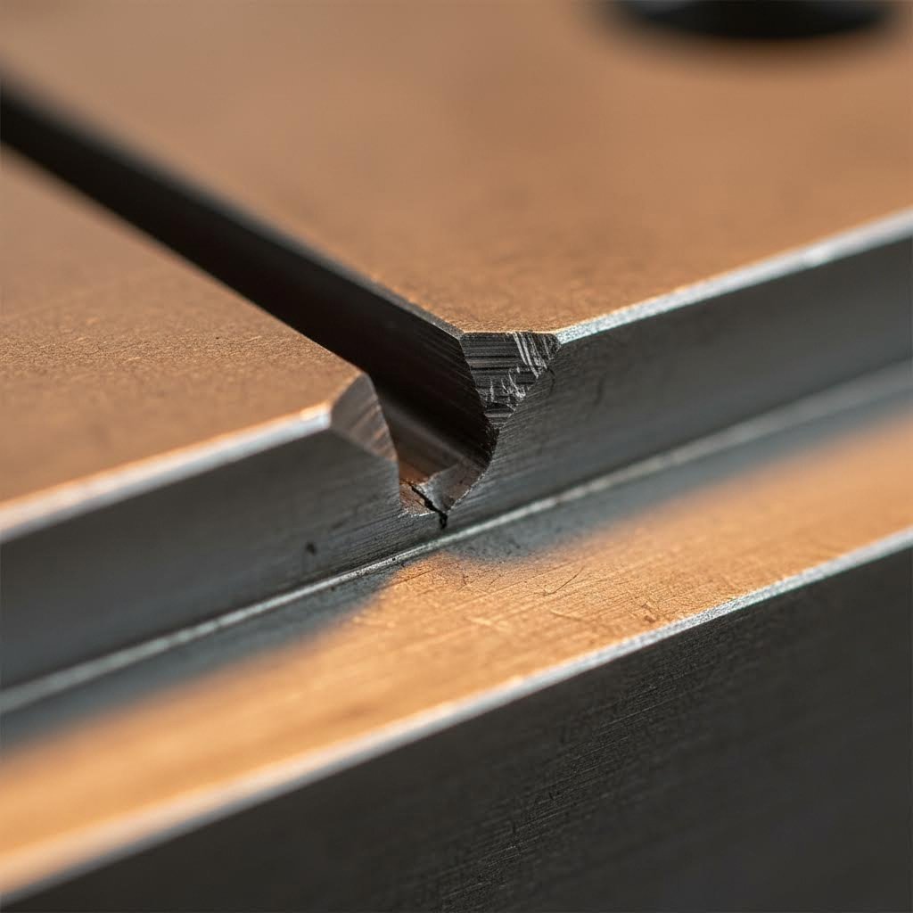
Bypass Notches and Material Flow Control
When forming operations stretch or draw material, controlling how that material flows becomes critical. Bypass notches in sheet metal stamping dies serve this exact purpose—they're strategically placed reliefs that allow material to move in controlled patterns during forming operations.
Think of it like scoring cardboard before folding—the notches create predetermined pathways for material movement, preventing uncontrolled buckling or tearing. Proper bypass notch design considers:
- Material thickness and ductility characteristics
- Draw depth and forming severity
- Blank holder forces and their distribution
- Final part geometry requirements
Without adequate material flow control, you'll see defects like splits (material stretched too thin), wrinkles (excess material with nowhere to go), or springback (material not fully formed to die geometry).
Tolerance Considerations and Achievable Precision
How tight can you hold tolerances with stamping dies? The answer depends on multiple variables working together. According to industry experience documented by U-Need, their engineers work with clients to determine which tolerances are critical and which can be loosened without impacting performance—a collaborative DFM strategy that balances precision and cost-effectiveness.
Factors affecting achievable precision include:
- Die configuration: Progressive dies generally deliver tighter tolerances than transfer dies due to continuous piloting
- Material properties: Springback varies significantly between aluminum, mild steel, and high-strength materials
- Part geometry: Complex three-dimensional forms present greater challenges than flat stampings
- Die wear: Tolerances drift over production runs as cutting edges dull and forming surfaces erode
- Press characteristics: Machine rigidity, parallelism, and repeatability all influence final part dimensions
For reference, precision stamping operations can achieve tolerances as tight as +/- 0.001mm on critical features, though this level of precision requires careful attention to every aspect of die design and manufacturing.
Venting and Slug Removal for Consistent Quality
Here's a detail that often gets overlooked: where does the air go when a punch drives into material at high speed? And where do the slugs (punched-out material) end up? Poor venting creates back-pressure that can affect forming operations and even float slugs back into the die—a condition that damages both tooling and parts.
Proper die design addresses these concerns through:
- Venting passages: Channels that allow trapped air to escape during high-speed operations
- Slug-free die design: Die openings with constricting tapers that grip slugs and prevent pull-back
- Adequate die penetration: Ensuring punches travel far enough to clear slugs into discharge areas
- Clear scrap paths: Unobstructed routes for slugs to exit the die area
Mate's technical guidance notes that regardless of sheet thickness, the recommended penetration of the punch into a slug-free die is 0.118" (3.00mm). This depth ensures reliable slug ejection and prevents the most common cause of die damage—slugs returning into the working area.
Modern CAD/CAM Integration in Die Design
Today's metal stamping die design leverages powerful digital tools that streamline the entire development process. According to U-Need, modern die design relies on software tools including 3D CAD platforms (SolidWorks, CATIA, Siemens NX) for detailed component modeling, and specialized CAD for progressive die development.
Computer-Aided Engineering (CAE) and Finite Element Analysis (FEA) software allow designers to simulate the entire stamping process digitally before any physical tooling is manufactured. Using platforms like AutoForm or DYNAFORM, engineers can predict material behavior, identify potential forming defects, and optimize die geometry—all virtually.
This simulation capability represents a significant shift in die development philosophy. As U-Need notes, it is far cheaper and faster to adjust a digital model than to re-machine hardened tool steel. Virtual validation de-risks projects, shortens physical tryout periods, and dramatically increases the probability of first-time success—a topic we'll explore in depth in the next section.
Modern Die Development with CAE Simulation Technology
Remember the days when die development meant building physical prototypes, testing them, finding defects, rebuilding, and repeating this cycle until something finally worked? That approach still exists—but it's rapidly becoming obsolete. Today's stamping technology leverages sophisticated computer-aided engineering (CAE) simulation that predicts exactly how sheet metal will behave before anyone cuts a single piece of tool steel.
According to Keysight's engineering research, simulation offers a powerful, cost-effective way to optimize processes, reduce errors, and enhance material efficiency. It digitally simulates the die process of forming sheet metal, enabling the detection and resolution of potential issues before actual production begins.
Why does this matter for your bottom line? The sheet metal stamping process involves complex material behaviors that are nearly impossible to predict through intuition alone. Advanced high-strength steels and aluminum alloys exhibit high springback magnitudes, making dimensional accuracy a constant challenge. When defects emerge during physical try-outs, corrections become both time-consuming and costly—sometimes impossible to resolve within production timelines.
How CAE Simulation Prevents Costly Die Revisions
Imagine being able to "test" your die design hundreds of times without manufacturing a single component. That's precisely what finite element analysis (FEA) delivers. This computational technique predicts and analyzes metal sheet behavior during the forming process, accounting for tool design, material properties, and process parameters simultaneously.
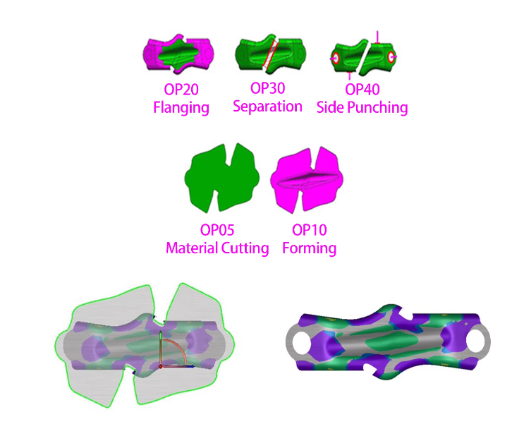
The metal stamping process simulation identifies critical defects before they become expensive problems:
- Springback prediction: The software calculates how materials will "bounce back" after forming, allowing engineers to compensate die geometry in advance
- Wrinkle detection: Virtual analysis reveals where excess material will accumulate and cause surface defects
- Material thinning: Simulation pinpoints areas where stretching exceeds safe limits, preventing cracks and splits
- Cosmetic defect identification: Advanced contour settings and virtual lightroom environments check aesthetic quality before physical prototyping
According to Keysight's research, simulation allows for testing different materials and designs without expensive physical prototypes, enabling faster innovation and more precise control over the final product. For automotive body panels—where aluminum doors or hoods can crack easily when parameters fluctuate slightly—this virtual validation prevents costly production errors by building robust process routes upfront.
The manufacturing stamping process benefits extend beyond defect prevention. Simulation software optimizes initial blank contour shapes to maximize material utilization, reducing waste and improving sustainability. It also predicts minimum required press force, enabling production planners to select appropriate die-stamping machine capacity with confidence.
Digital Engineering Workflows in Modern Die Development
Here's where traditional and modern approaches diverge dramatically. The conventional die development cycle looked something like this: design, build prototype, test, discover problems, redesign, rebuild, retest—often repeating multiple times before achieving acceptable results. Each iteration consumed weeks and substantial budget.
Modern digital workflows compress this timeline significantly. Research indicates that virtual die tryouts allow manufacturers to identify potential issues like wrinkles, splits, or excessive thinning before actual production begins. This proactive approach optimizes material flow and ensures metal forms correctly into desired shapes—particularly beneficial with challenging materials or complex geometries.
The sheet metal stamping process now integrates seamlessly with high-performance computing (HPC) for large-scale simulations. Engineers can run hundreds of virtual iterations overnight, testing parameter variations that would require months of physical experimentation. Key workflow advantages include:
- Automated springback compensation: Software automatically adjusts tool geometry per operation and recreates CAD surfaces for compensated tools
- Rapid design iteration: Digital modifications cost a fraction of re-machining hardened tool steel
- Seamless CAD integration: Results flow directly back to platforms like CATIA and Unigraphics
- Die wear prediction: Contact pressures and material flow analysis enable proactive wear reduction measures
Companies investing in these digital capabilities see measurable results. For example, Shaoyi's advanced CAE simulation approach delivers a 93% first-pass approval rate on automotive stamping die production—dramatically reducing the revision cycles that traditionally plagued tooling development. Their rapid prototyping capability produces results in as little as 5 days, demonstrating how digital workflows compress development timelines that once stretched across months.
Virtual validation de-risks projects, shortens physical tryout periods, and dramatically increases first-time success probability.
The financial implications are substantial. When you eliminate three or four physical prototype iterations—each costing weeks of time and thousands in materials and machining—the simulation software investment pays for itself quickly. Factor in faster market entry and reduced opportunity costs, and the ROI becomes compelling even for mid-volume production scenarios.
Additionally, simulation helps organizations meet environmental regulations by optimizing energy use and minimizing waste. Can a press with less power form the part? Can one operation be eliminated from a press line? These questions, answered virtually, translate directly to sustainability improvements and operational cost reductions.
Of course, even the most sophisticated simulation cannot prevent all issues. Physical dies still require maintenance and eventually wear—topics that deserve careful attention to protect your tooling investment over its operational lifetime.
Die Maintenance and Troubleshooting Common Problems
Even the best-designed dies eventually show signs of wear. The question isn't whether your stamping tooling will need maintenance—it's whether you'll catch problems early enough to prevent costly production disruptions. According to Wisconsin Metal Parts, there are tell-tale signs that a stamping tool may be in need of maintenance, including burrs on your parts, tolerances going out of spec, increased tonnage, or hearing noises from your tool.
The good news? Understanding common die wear patterns helps you predict problems before they become emergencies. Let's explore what causes die stamping issues and how proactive maintenance extends the life of your metal stamped parts production.
Recognizing Early Warning Signs of Die Wear
Your stamped parts tell a story—if you know how to read them. When die stamps begin wearing, subtle changes appear in part quality long before catastrophic failure occurs. Here's what to watch for:
Edge Wear: This gradual dulling of cutting edges represents the most common wear pattern. You'll notice it first as slightly larger burrs on part edges or increased force required to complete the stamping process. According to DGMF Mold Clamps, die stamping molds are prone to different amounts of wear on each side position of the punch core, with some parts showing larger scratches and wearing faster—particularly pronounced on thin and narrow rectangular dies.
Galling: When material transfers from the workpiece to the die surface, you're seeing galling. This adhesive wear creates rough patches that mar subsequent parts and accelerates further degradation. Watch for scratched or scored surfaces on your die stamped components.
Chipping: Small fractures along cutting edges indicate excessive stress or improper clearance. Chipping typically signals either material issues, alignment problems, or operation beyond design parameters.
The main causes of uneven wear include:
- Machine tool turret design or processing accuracy issues—particularly misalignment between upper and lower turntable mounting seats
- Mold design or accuracy not meeting requirements
- Insufficient precision in the die guide bush
- Improper clearance settings
- Long-term wear affecting mold mount or guide bush alignment
Sometimes problems only manifest when the die is running. As Wisconsin Metal Parts notes, seeing the tool run in person or reviewing video footage of the die in action proves incredibly beneficial to diagnosing issues. The problem could stem from how the tool is set up in the press, the press itself being worn, or prematurely wearing items due to the tool steel types used.
Preventive Maintenance Schedules That Extend Die Life
Here's the reality: reactive maintenance costs significantly more than prevention. When you wait for failures, you're paying for emergency repairs, scrapped parts, production delays, and potentially damaged tooling that requires complete replacement rather than simple refurbishment.
Establishing the right maintenance interval depends on several factors:
| Factor | Lower Frequency Needed | Higher Frequency Needed |
|---|---|---|
| Production Volume | Under 50,000 hits/month | Over 200,000 hits/month |
| Material Hardness | Aluminum, mild steel | Stainless, high-strength steel |
| Material Thickness | Thin gauge (<1mm) | Heavy gauge (>3mm) |
| Part Complexity | Simple blanks | Deep draws, tight tolerances |
| Die Age | Newly refurbished | Multiple production campaigns |
A practical preventive maintenance approach includes:
- Regular alignment checks: Use alignment mandrels to verify machine tool turret and mounting base alignment periodically
- Timely guide bush replacement: Don't wait for visible wear—schedule replacements based on production counts
- Clearance verification: Check punch-to-die clearance after every major production run
- Documentation: Save the last part from each production run along with the end strip—these provide valuable diagnostic information for toolmakers
Going forward, keeping a preventative maintenance schedule helps reduce problems and catch issues before they become large, expensive fixes. This information also helps predict when future PM might be needed, allowing you to plan ahead and reduce stamping die downtime.
Troubleshooting Common Stamping Defects
When quality issues emerge, systematic troubleshooting saves time and money. Use this checklist to identify likely stamp die-related causes for common defects:
-
Excessive burrs:
- Dull cutting edges requiring sharpening
- Clearance too large between punch and die
- Worn guide bushings causing misalignment
-
Dimensional drift:
- Progressive die wear changing cutting dimensions
- Thermal expansion during extended runs
- Worn pilots causing inconsistent strip positioning
-
Surface quality degradation:
- Galling on die surfaces requiring polishing or coating
- Slug pulling leaving marks on finished parts
- Insufficient lubrication during forming operations
-
Increased press tonnage:
- Dull cutting edges requiring more force
- Clearance too tight creating excessive friction
- Material buildup on die surfaces
-
Unusual noises:
- Misalignment between punch and die
- Loose die components
- Slug ejection problems
To prevent inconsistent die wear, DGMF Mold Clamps recommends adopting full guiding range dies, strengthening operator responsibility to find causes quickly, and considering special or forming molds to improve production efficiency—though forming molds typically cost 4-5 times more than ordinary molds.
Regrinding Versus Replacement: The Economic Decision
When your die stamps show wear, you face a critical decision: sharpen and continue, or invest in new components? The fix might be as simple as sharpening, or it could need more in-depth troubleshooting to determine why the tool isn't operating as intended.
Regrinding makes economic sense when:
- Wear is limited to cutting edges that can be restored
- Overall die geometry remains within tolerance
- Sufficient material remains for multiple regrind cycles
- Production requirements don't demand immediate turnaround
Replacement becomes necessary when:
- Chipping or damage extends beyond surface-level wear
- Multiple regrind cycles have consumed available material
- Die geometry has drifted beyond correction limits
- Component design changes require new tooling anyway
A good tool and die maker can help decipher the clues your tooling provides and tell that tool's story. Wisconsin Metal Parts emphasizes that having the tooling design available, along with part prints and inspection reports, greatly helps toolmakers troubleshoot effectively. Identifying higher wear items allows you to have spare components ready to install as needed—minimizing downtime when maintenance becomes necessary.
The relationship between preventive maintenance and die longevity is straightforward: consistent attention to small issues prevents catastrophic failures. When you track production counts, document quality trends, and schedule maintenance proactively, your stamping process delivers consistent results across extended production campaigns. With maintenance protocols established, the next consideration involves understanding the full cost picture—including how tooling investments translate to production ROI.
Cost Factors and ROI Analysis for Stamping Die Investment
Here's the question that keeps manufacturing managers up at night: how much should you actually spend on stamping tool and die investments? The answer isn't straightforward—because the initial purchase price tells only a fraction of the story. According to The Fabricator, there is no perfect formula or equation for deriving tooling cost, but numerous factors can be considered to help increase estimate accuracy.
What separates smart tooling investments from costly mistakes? Understanding total cost of ownership, matching die for manufacturing complexity to actual production needs, and knowing when premium tooling pays off versus when simpler solutions suffice.
Production Volume Thresholds for Different Die Types
Imagine buying a sports car to commute two miles to work—technically functional, but economically absurd. The same logic applies to manufacturing die selection. Your annual production volume should drive your tooling investment decisions more than any other factor.
When high volumes of parts are needed, the die typically is designed with larger, thicker, and higher-quality tool steel sections, according to industry experts. Higher volumes also warrant the use of alternative tooling materials, such as solid carbide. Conversely, dies manufacturing low-volume parts typically use less expensive tool steel, or sometimes even cast or molded composite materials.
Here's a practical framework for matching volume to die investment:
- Under 10,000 parts annually: Simple single-station dies or even prototyping-grade tooling often suffice. Class C dies—made for short-term prototype applications—deliver acceptable quality without excessive investment.
- 10,000 to 50,000 parts annually: Class B dies designed for small volumes with limited life become economically appropriate. Compound or combination dies offer good value at these volumes.
- 50,000 to 200,000 parts annually: Progressive dies begin making economic sense. The higher upfront cost spreads across enough parts to reduce per-piece tooling amortization.
- Over 200,000 parts annually: Class A dies designed for high production and ease of maintenance become essential. These custom metal stamping dies can produce extreme volumes where additional tooling cost becomes insignificant on a per-part basis.
The break-even calculation is straightforward: divide your total die investment by expected production volume, then compare per-part tooling cost against alternative manufacturing methods or simpler die configurations.
Calculating Total Cost of Ownership for Stamping Tooling
That quote you received for a progressive die? It represents maybe 60% of what you'll actually spend over the tool's lifetime. Total cost of ownership encompasses factors that many purchasers overlook until invoices arrive.
| Cost Factor | Simple Dies | Progressive Dies | Transfer Dies |
|---|---|---|---|
| Initial Tooling Cost | Lower ($10K-50K typical) | Higher ($100K-500K typical) | Highest ($150K-750K typical) |
| Maintenance Frequency | Lower (fewer components) | Moderate (multiple stations) | Higher (transfer mechanisms) |
| Downtime Impact | Minimal (quick changeover) | Moderate (complex setup) | Significant (system complexity) |
| Per-Part Production Cost | Higher (slower cycles) | Lower (high-speed operation) | Moderate (larger parts) |
| Spare Parts Investment | Minimal | Moderate (wear components) | Higher (mechanical systems) |
| Operator Skill Required | Basic | Intermediate | Advanced |
Beyond these direct costs, consider part quality factors. A manufacturing die that produces parts requiring secondary operations—deburring, straightening, or rework—costs more than its purchase price suggests. Metal stamping presses running at optimal efficiency require tooling matched to their capabilities; mismatches create hidden costs through reduced cycle rates or excessive wear.
Delivery timeline also affects pricing. According to The Fabricator, a request for very short delivery time on the tool most likely will inflate tooling cost—especially if the tooling provider currently has a large workload. Expediting a delivery date requires overtime, which increases cost.
Domestic Versus Offshore Sourcing Trade-offs
The labor rate differential between domestic and offshore die manufacturing is real—and substantial. China and India have considerably lower labor rates than the U.S., meaning tooling cost typically is lower in these countries. But lower quotes don't always translate to lower total costs.
Factors to weigh in sourcing decisions:
- Communication complexity: Technical specifications for stamping manufacturing require precise understanding. Language barriers and time zone differences can create costly misinterpretations.
- Iteration speed: When die modifications are needed, domestic suppliers typically respond faster. Offshore revisions may add weeks to development timelines.
- Quality verification: Inspecting tooling before shipment requires either travel or trusting remote quality processes.
- Logistics and duties: Shipping large dies internationally adds cost and risk. Import duties may narrow the price gap significantly.
- Support availability: When problems arise during production, local suppliers provide faster troubleshooting assistance.
For large tooling—such as dies that produce autobody panels—financing costs also matter. The Fabricator notes it's not uncommon for die shops to borrow money to buy materials necessary to build large tooling. The longer it takes to receive payment, the more interest the shop pays—often reflected in quoted prices. Occasionally, customers make progress payments to reduce this cost.
How Complexity Drives Die Pricing
A part with difficult geometry increases the number of stations necessary to make it, directly increasing tooling cost. Parts with tight tolerancing also require additional stations. If the part is made from high-strength materials, higher grades of tool steel are needed to cut and form it—further raising the manufacturing die investment.
Price drivers include:
- Number of operations: Each additional forming, cutting, or bending station adds design and manufacturing cost
- Tolerance requirements: Tighter specifications demand more precise tooling and extended development time
- Material selection: Dies made from premium tooling materials like carbide take more time to manufacture—the material requires more machining time, plus wire-burning and diamond-finishing processes that are relatively expensive
- Spring selection: Low-volume dies might use simple coil springs, while high-volume dies typically use longer-life, more expensive gas springs
- Supplier capacity: Finding a shop with the right capacity and experience yields lower quotes than forcing an overloaded or underqualified supplier
The estimating process itself matters. According to The Fabricator, the person estimating die cost must understand sheet metal processing methods and die design thoroughly, because cost can only be established after process steps are determined. Many quoting engineers keep historical records of previous quotes, reviewing whether the company made or lost money on similar projects to improve future accuracy.
Understanding these cost dynamics positions you to evaluate quotes intelligently and make tooling investments that deliver genuine ROI. However, cost represents just one dimension of the decision—selecting the right stamping die partner involves evaluating technical capabilities, quality systems, and long-term support that ultimately determine whether your investment succeeds.
Selecting the Right Stamping Die Partner for Your Application
You've explored die types, material selection, engineering fundamentals, simulation technology, maintenance protocols, and cost considerations. Now comes the decision that ties everything together: choosing the right stamping die manufacturer to partner with. This choice determines whether your tooling investment delivers consistent returns or becomes an ongoing headache.
What is dies in manufacturing if not the foundation of your production capability? The partner who designs and builds those dies becomes integral to your success. Unlike commodity purchases where the lowest bid wins, sheet metal stamping tooling requires evaluating technical expertise, quality systems, and long-term support capabilities that directly impact your production outcomes.
Think about it this way—your stamping die manufacturers aren't just selling you a tool. They're providing engineering expertise, quality assurance, and ongoing support that either enables or limits your manufacturing potential. The framework below helps you make this critical decision systematically.
Building Your Die Selection Criteria Checklist
Before evaluating potential suppliers, clarify exactly what your application demands. Rushing to request quotes without this preparation leads to mismatched expectations and costly revisions later. Consider these essential criteria:
Application Requirements Analysis:
- What specific operations must the die perform? (blanking, piercing, forming, drawing)
- What are the critical dimensions and their allowable tolerances?
- Are there cosmetic surface requirements or functional specifications?
- What secondary operations, if any, will parts require?
Material Considerations:
- What sheet metal will you be processing? (aluminum, mild steel, stainless, high-strength grades)
- What thickness range must the die accommodate?
- Are there grain direction or material specification requirements?
- How does your material selection affect expected die wear patterns?
Volume Projections:
- What annual production volume do you anticipate?
- Is demand stable or highly variable?
- What's your expected product lifecycle?
- Will volumes justify progressive die investment or suffice with simpler configurations?
Tolerance Specifications:
- Which dimensions are functionally critical versus cosmetic?
- What measurement methods will verify conformance?
- How do tolerance requirements compare to industry benchmarks for your material and geometry?
- Have you validated that specified tolerances are actually achievable?
Documenting these requirements before supplier conversations ensures you're comparing quotes on equivalent scope. Metal parts stamping complexity varies dramatically—a supplier quoting on incomplete specifications may deliver unwelcome surprises.
Evaluating Die Manufacturers for Long-Term Partnership
With your requirements defined, evaluating potential metal stamping die manufacturers becomes more objective. The following step-by-step process helps identify partners capable of meeting your technical and commercial needs:
- Verify relevant certifications. For automotive stamping dies, IATF 16949 certification demonstrates that a supplier maintains quality management systems meeting automotive industry standards. This certification isn't just paperwork—it indicates documented processes, trained personnel, and continuous improvement culture. Other industries may require ISO 9001, AS9100 for aerospace, or ISO 13485 for medical devices.
- Assess technical capabilities. Can the supplier handle your die complexity? Evaluate their design software platforms, simulation capabilities, machining equipment, and inspection technology. Ask specifically about experience with similar applications, materials, and tolerance requirements.
- Review engineering support depth. What is die manufacturing without engineering expertise? The best automotive stamping die partners offer collaborative design support—identifying cost reduction opportunities, suggesting design modifications that improve manufacturability, and providing DFM feedback before tooling begins.
- Examine quality systems. Beyond certifications, understand how the supplier verifies die performance. What inspection protocols do they follow? How do they document first-article approval? What measurement equipment validates critical dimensions?
- Evaluate prototyping capabilities. Speed to first parts matters. Suppliers offering rapid prototyping—some achieving results in as little as 5 days—compress development timelines significantly. This capability proves especially valuable when design iterations are likely.
- Investigate production track record. Ask about first-pass approval rates. A supplier consistently achieving 93% or higher first-pass approval demonstrates process control that reduces your development risk and accelerates production launch.
- Understand ongoing support. Dies require maintenance, modifications, and occasionally troubleshooting. What support does the supplier provide after delivery? Are spare parts readily available? How quickly can they respond to production issues?
- Check references and case studies. Request references from customers with similar applications. Ask specifically about communication quality, on-time delivery performance, and problem resolution when issues arose.
This evaluation framework applies whether you're sourcing domestically or globally. For complex automotive stamping die applications, geographic proximity to your production facility can accelerate troubleshooting and reduce logistics complexity—factors worth weighing against cost differentials.
Why Engineering Partnership Matters
Here's something many purchasers overlook: the best stamping die manufacturers don't just build what you specify—they help you specify correctly in the first place. This engineering partnership approach proves especially valuable for complex applications where small design decisions cascade into significant production impacts.
Qualified partners bring experience across hundreds or thousands of similar projects. They've seen what works, what fails, and what optimizations yield the best balance of cost and performance. When evaluating suppliers, look for those who ask probing questions about your application rather than simply quoting your specifications verbatim.
For automotive applications specifically, OEM standards create additional complexity. Suppliers experienced with these requirements understand documentation expectations, material traceability needs, and approval protocols that unfamiliar suppliers may struggle to navigate.
The right partner doesn't just deliver tooling—they deliver confidence that your production will perform as expected.
Companies like Shaoyi exemplify this partnership approach, combining IATF 16949 certification with comprehensive mold design and fabrication capabilities. Their engineering team focuses on delivering cost-effective tooling tailored to OEM standards—exactly the combination that reduces risk for manufacturers entering production. For readers seeking precision stamping die solutions, exploring their capabilities at shao-yi.com/automotive-stamping-dies provides a concrete example of what qualified automotive stamping die partnership looks like.
Making Your Final Selection
After completing evaluations, your decision should balance multiple factors:
- Technical fit: Can this supplier actually deliver what your application requires?
- Commercial alignment: Does pricing reflect fair value for the capabilities offered?
- Risk profile: What happens if problems arise during development or production?
- Relationship potential: Is this a supplier you can work with effectively over years of production?
The sheet metal stamping decision ultimately comes down to confidence. Confidence that your tooling will perform. Confidence that quality will remain consistent. Confidence that support will be available when you need it. The evaluation framework above helps you build that confidence systematically rather than relying on hope or habit.
Your stamping die investment represents significant capital deployed toward future production capability. Selecting the right partner transforms that investment into competitive advantage—delivering quality parts, on schedule, at costs that support your business objectives. Take the time to evaluate thoroughly, and your tooling will reward that diligence across millions of production cycles.
Frequently Asked Questions About Sheet Metal Stamping Dies
1. What is sheet metal stamping dies?
Sheet metal stamping dies are precision tools consisting of male (punch) and female (die) components that cut, bend, shape, or form flat sheet metal into three-dimensional parts. They work within a press to apply controlled force, transforming raw material into finished components. These tools are essential in high-volume manufacturing, particularly automotive and consumer goods industries, where consistency and repeatability are critical for producing millions of identical parts.
2. How much does a metal stamping die cost?
Metal stamping die costs vary significantly based on complexity, production volume requirements, and material specifications. Simple dies may range from $10,000 to $50,000, while progressive dies typically cost $100,000 to $500,000. Transfer dies for large automotive panels can reach $750,000 or more. Total cost of ownership includes maintenance, spare parts, and downtime factors beyond the initial investment. Higher production volumes justify premium tooling investments as per-part costs decrease substantially.
3. What is the difference between die cut and stamping?
Die cutting and metal stamping are distinct processes. Die cutting typically refers to cutting flat materials like paper, cardboard, or thin plastics using sharp steel rule dies. Metal stamping involves forming sheet metal through various operations including blanking, piercing, bending, and drawing using hardened tool steel dies within a press. Stamping is almost always a cold working process using sheet metal blanks or coils, while die casting uses molten metal poured into molds.
4. What are the main types of stamping dies and when should I use each?
The four primary types are progressive dies (best for high-volume production of smaller parts over 100,000 units annually), transfer dies (ideal for large, complex parts requiring movement between stations), compound dies (suited for precision flat parts at low to medium volumes), and combination dies (useful when parts require both cutting and forming operations). Selection depends on part complexity, production volume, tolerance requirements, and budget constraints.
5. How does CAE simulation improve stamping die development?
CAE simulation transforms die development by virtually testing designs before manufacturing physical tooling. It predicts material behavior, identifies defects like springback and wrinkling, and optimizes die geometry digitally. This technology reduces development iterations, shortens timelines, and increases first-pass success rates. Companies using advanced simulation achieve approval rates exceeding 93% while compressing prototyping to as little as 5 days, significantly reducing costs compared to traditional trial-and-error approaches.