 Small batches, high standards. Our rapid prototyping service makes validation faster and easier —

Why Top Die Shops Are Switching To Nitrogen Gas Springs In Stamping
Understanding Nitrogen Gas Springs and Their Role in Stamping
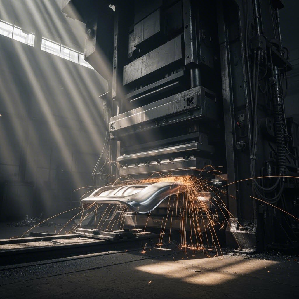
Ever wondered why precision stamping operations consistently deliver flawless parts while others struggle with inconsistent results? The answer often lies in a critical component that many overlook: nitrogen gas springs in stamping dies. These seemingly simple devices have revolutionized how die shops approach force management, transforming unpredictable stamping processes into reliable, repeatable operations.
A gas spring functions as a self-contained force delivery system that provides controlled pressure throughout the entire working stroke. Unlike traditional mechanical springs that deliver varying force depending on compression, nitrogen gas cylinders maintain remarkably consistent pressure from start to finish. This consistency is what makes them indispensable in modern stamping applications.
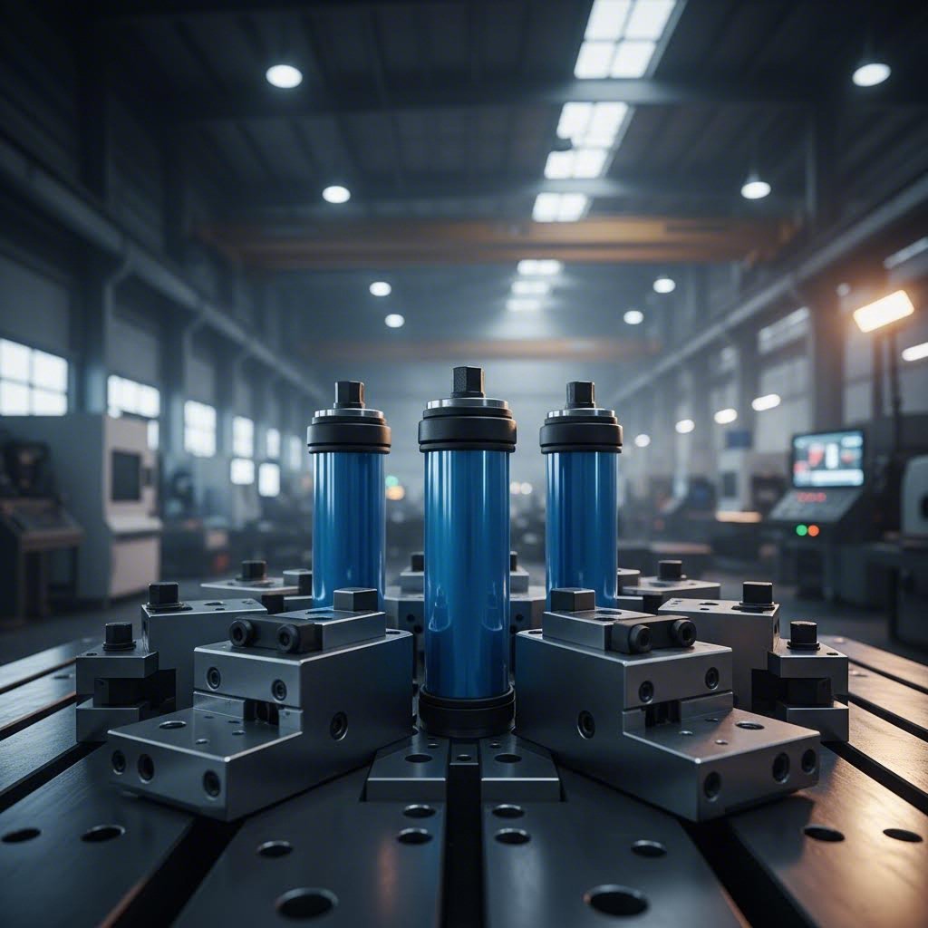
A nitrogen gas spring is a sealed cylinder containing pressurized nitrogen gas that provides controlled, consistent force throughout its stroke cycle, enabling precise blank holding, stripping, and forming operations in stamping dies.
What Makes Nitrogen Gas Springs Essential for Stamping
Imagine pressing a sheet of metal into a complex automotive panel. You need consistent pressure holding that blank in place throughout the entire forming process. Too little force and the material wrinkles. Too much force and you risk tearing. Traditional springs simply cannot deliver the precision required for today's demanding applications.
So how do gas springs work to solve this challenge? The principle is elegantly simple. Compressed nitrogen gas is sealed within a precision-machined cylinder. When the piston rod is compressed during the die's closing stroke, the nitrogen gas compresses and stores energy. This stored energy then provides the force needed to perform critical functions like blank holding, cam return, and part stripping.
What sets these components apart is their ability to deliver near-constant force regardless of position. While a conventional coil spring might vary its force output by 20% or more across its working range, a properly selected nitrogen system keeps that variation to just a few percent.
The Science Behind Controlled Force Delivery
Understanding how gas springs work requires a basic grasp of gas behavior under pressure. Nitrogen, an inert gas that won't corrode internal components, is compressed within the sealed cylinder at pressures typically ranging from 150 to 2,000 psi or higher. When you compress the piston, the gas pressure increases according to well-established thermodynamic principles.
The key advantage lies in the compressibility of nitrogren gas compared to hydraulic fluids or mechanical spring materials. Gas compresses smoothly and predictably, absorbing variations in die closure and material thickness without the harsh force spikes that can damage tooling or parts.
For stamping professionals seeking precision and efficiency, this technical foundation matters significantly. When you understand these principles, you can properly specify components for your application, troubleshoot performance issues, and optimize die designs for maximum productivity.
This comprehensive resource aims to fill the educational gap that exists around these critical components. Rather than focusing on specific products, the goal here is to equip you with the knowledge needed to make informed decisions about integrating this technology into your stamping operations.
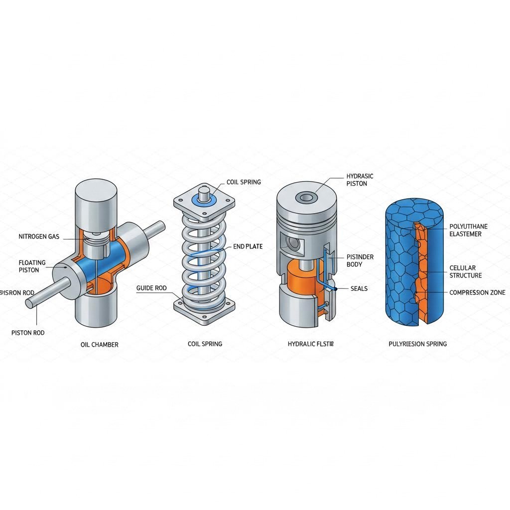
Nitrogen Gas Springs Versus Alternative Force Systems
When you're designing or upgrading a stamping die, choosing the right force delivery system can make or break your operation. You've got options: mechanical springs, hydraulic systems, polyurethane springs, or nitrogen gas springs. But which one actually fits your application? Let's break down each technology so you can make an informed decision based on real performance characteristics rather than guesswork.
Force Consistency Across Different Spring Technologies
Think about what happens when you compress a traditional coil spring. The harder you push, the more resistance you encounter. This progressive force curve might work fine for some applications, but in precision stamping, it creates headaches. Your blank holding force at the beginning of the stroke differs significantly from the force at the end, potentially causing wrinkling, tearing, or dimensional inconsistencies.
Gas spring shocks operate on an entirely different principle. The compressed nitrogen inside a gas spring cylinder provides nearly flat force output across the working stroke. This means your blank holder applies consistent pressure whether the die is just beginning to close or reaching full compression. For operations requiring tight tolerances, this consistency translates directly into better part quality.
Hydraulic systems also deliver consistent force, but they come with complexity. You're dealing with pumps, valves, hoses, and fluid management. Gas pistons in a nitrogen spring eliminate this infrastructure entirely since each unit is self-contained and ready to install.
Polyurethane springs fall somewhere in the middle. They're compact and cost-effective, but their force curve is even steeper than mechanical springs. They also degrade faster under heat and repeated cycling, making them better suited for lower-volume applications.
When Each Spring Type Excels in Stamping Applications
Sounds complex? Here's a practical way to think about it. Each spring technology has a sweet spot where it outperforms the alternatives:
- Mechanical coil springs work well for simple stripping operations where force variation is acceptable and cost is the primary concern.
- Hydraulic systems excel in extremely high-force applications or where force needs to be adjustable during operation.
- Polyurethane springs fit tight spaces in lower-cycle applications where their progressive force curve isn't problematic.
- Nitrogen gas springs dominate in precision stamping where consistent force, compact packaging, and long service life are priorities.
The following comparison table provides a clear framework for evaluating these technologies against the factors that matter most in stamping die applications:
| Characteristic | Nitrogen Gas Springs | Mechanical Springs | Hydraulic Systems | Polyurethane Springs |
|---|---|---|---|---|
| Force Consistency | Excellent (near-constant) | Poor (progressive curve) | Excellent | Poor (steep progressive) |
| Maintenance Requirements | Low (periodic inspection) | Low (replacement when fatigued) | High (fluid, seals, pumps) | Moderate (frequent replacement) |
| Typical Lifespan | 1-2 million cycles | Variable (fatigue-dependent) | Long with maintenance | 100,000-500,000 cycles |
| Initial Cost | Moderate to High | Low | High (system cost) | Low |
| Space Requirements | Compact | Large (for equivalent force) | Large (external equipment) | Very Compact |
| Ideal Applications | Precision forming, blank holding, high-cycle production | Simple stripping, cost-sensitive applications | Very high force, adjustable force needs | Low-cycle, space-constrained applications |
When evaluating a spring cylinder for your specific operation, consider your production volume first. High-cycle applications benefit enormously from the durability and consistency of nitrogen systems. Lower-volume jobs might tolerate the limitations of mechanical or polyurethane options.
Also consider the total cost of ownership rather than just the upfront investment. A gas spring cylinder with a million-cycle lifespan costs more initially but may prove far more economical than replacing polyurethane springs every few months or maintaining complex hydraulic infrastructure.
With this comparison framework in mind, you're better equipped to match the right technology to your stamping requirements. But choosing nitrogen gas springs is just the first step. Understanding the different configurations available helps you select the optimal unit for your specific die design constraints.
Types of Nitrogen Gas Springs for Stamping Dies
So you've decided nitrogen gas springs are the right choice for your stamping operation. Now comes the next question: which configuration fits your die design? Not all gas springs are created equal, and selecting the wrong size or style can compromise both performance and die longevity. Let's explore the different types available and when each makes sense.
The beauty of modern nitrogen spring technology lies in its versatility. Manufacturers offer everything from robust self-contained units designed for heavy-duty applications to miniature gas springs that fit into impossibly tight spaces. Understanding these options helps you match the right component to your specific stamping challenge.
Matching Spring Size to Die Space Constraints
Imagine you're designing a progressive die with limited vertical clearance. Traditional large-diameter springs simply won't fit. This is where small gas springs and compact configurations become invaluable. They deliver surprising force output from packages that tuck neatly into constrained die sections.
Here's how the main configuration types break down:
- Self-contained standard units represent the workhorse of stamping applications. These offer the widest range of force outputs and stroke lengths. When space isn't severely limited, they're typically the first choice due to their proven reliability and ease of installation.
- Compact designs reduce overall height while maintaining substantial force capability. They're ideal for dies where shut height is critical but you still need significant blank holding or stripping force.
- Miniature gas spring options pack impressive performance into remarkably small packages. Mini gas springs excel in intricate progressive dies, small part stamping, and applications where multiple springs must fit within tight cluster arrangements.
- Ultra-compact and micro configurations push the boundaries of miniaturization. When every millimeter counts, these specialized units deliver controlled force from dimensions that seem almost impossibly small.
When you're evaluating die space, don't just measure the cavity where the spring will sit. Consider the mounting hardware, any required guide mechanisms, and clearance for the rod during full extension. A spring that technically fits might not allow proper installation or maintenance access.
Force Output Considerations for Different Configurations
Here's something that trips up many engineers: smaller doesn't always mean weaker. Modern miniature gas springs achieve force outputs that would have required much larger units just a decade ago. However, physics still applies. Generally speaking, larger cylinder diameters accommodate higher pressures and deliver greater total force.
When selecting the right configuration, work through these key criteria systematically:
- Available mounting space: Measure the actual cavity dimensions in your die, accounting for clearances and access requirements.
- Required force output: Calculate the total force needed for your application, whether blank holding, stripping, or cam return. Add appropriate safety margins.
- Stroke length needs: Ensure the spring's working stroke matches your die's requirements. Too short and you won't achieve full function. Too long wastes space and may affect force characteristics.
- Cycle rate requirements: High-speed stamping operations generate heat and demand components rated for rapid cycling. Some compact designs handle high cycles better than others.
- Mounting orientation: Certain configurations perform optimally in specific orientations. Verify that your intended mounting position is supported.
For applications requiring multiple springs working in parallel, miniature gas springs often provide more flexibility than a single large unit. You can distribute force more evenly across the die surface and fine-tune the force balance by adjusting individual spring placement.
The trend in modern die design favors compact and miniature configurations wherever possible. They allow more design freedom, reduce die weight, and often simplify maintenance by making individual units easier to access and replace.
Selecting the right spring type and size is crucial, but it's only part of the equation. Understanding how to calculate the actual force requirements ensures you specify components that perform exactly as needed in your stamping application.
Force and Pressure Calculations for Proper Spring Selection
You've identified the right spring configuration for your die design. But how do you know it will deliver the exact force your stamping operation requires? This is where many engineers struggle. Understanding the relationship between nitrogen pressure, cylinder dimensions, and force output throughout the stroke cycle is essential for proper specification. Let's demystify these calculations so you can confidently select components that perform precisely as needed.
The force a cylinder nitrogen gas spring produces isn't magic. It follows straightforward physical principles. When you grasp these fundamentals, you'll be equipped to calculate requirements for any stamping application rather than relying solely on manufacturer recommendations or trial-and-error approaches.
Calculating Required Force for Your Stamping Operation
Before diving into spring specifications, you need to determine exactly how much force your application demands. This starts with understanding what the spring must accomplish within your die.
For blank holding applications, the spring must generate enough force to control material flow during forming without causing tears or excessive thinning. Too little force allows wrinkling. Too much force restricts material movement and causes splits. The optimal blank holder force depends on material type, thickness, part geometry, and forming depth.
Stripping operations present different requirements. Here, the spring must overcome the friction and mechanical interference holding the formed part to the punch or die components. Stripping force typically ranges from a percentage of the forming force, varying based on part complexity and surface conditions.
Follow this systematic approach to determine your force requirements:
- Identify the primary function: Determine whether the spring serves blank holding, stripping, cam return, or another purpose. Each function has different force calculation methods.
- Calculate base force requirements: For blank holding, consider material properties, blank size, and draw depth. For stripping, evaluate part geometry and surface area in contact with tooling.
- Account for force distribution: If using multiple springs, divide the total required force among them. Consider positioning to ensure even pressure distribution across the working surface.
- Apply appropriate safety factors: Industry practice typically adds 20-30% beyond calculated minimums to account for material variations, tool wear, and process fluctuations.
- Verify stroke requirements: Ensure the spring's working stroke accommodates your die travel with margin for adjustment and wear compensation.
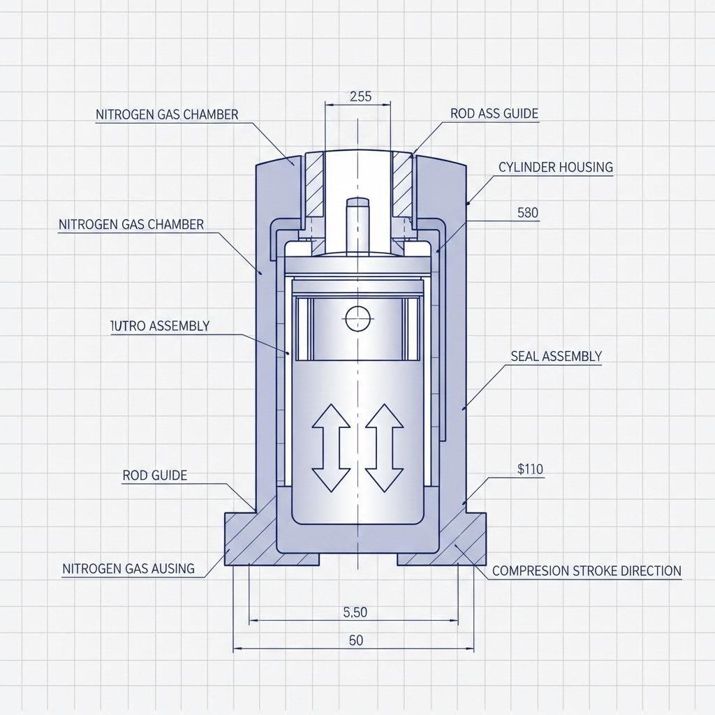
Understanding Pressure Changes During the Stroke Cycle
Here's where nitrogen gas springs differ fundamentally from mechanical springs. When you compress a nitrogen spring, the gas pressure increases according to gas laws. This pressure change directly affects force output throughout the stroke.
Every nitrogen spring has two critical pressure specifications: initial pressure and final pressure. Initial pressure refers to the gas charge when the spring is at its extended position. As the piston compresses, reducing the gas volume, pressure rises to the final working pressure at full stroke.
The relationship between these pressures determines the force curve. A spring with a longer stroke relative to its gas volume will experience greater pressure rise, meaning more force variation between the extended and compressed positions. Shorter stroke-to-volume ratios yield flatter force curves with more consistent output.
Consider this practical example of the concept. When you specify a spring with certain mm of nitrogen gas column and compress it by a specific stroke length, the resulting pressure increase follows predictable patterns. The nitrogen mm dimension essentially describes the gas volume available within the cylinder, which directly influences how pressure behaves during compression.
Understanding mm nitrogen specifications helps you predict force characteristics. Springs with greater nitrogen volume relative to stroke length maintain more consistent force because the percentage of volume change during compression remains smaller. This is why compact springs with minimal gas volume may exhibit steeper force curves than standard configurations with more generous proportions.
For precision stamping applications, aim for force variation of 15% or less across the working stroke. This typically requires matching stroke length to spring capacity so the compression ratio stays within optimal ranges. Manufacturer data sheets typically provide force at extended and compressed positions, allowing you to calculate the variation percentage.
When specifying springs for critical blank holding applications, consider the force at the exact die position where control matters most. If your forming operation is most sensitive at mid-stroke, verify the force output at that specific point rather than just the endpoints.
Temperature also affects pressure and force output. As stamping operations generate heat, nitrogen pressure inside the spring increases slightly. High-cycle applications should account for this thermal effect when calculating force margins. Operating temperature specifications in manufacturer data indicate the acceptable range where force predictions remain accurate.
With your force requirements calculated and pressure behavior understood, the next critical step is ensuring proper installation. Even perfectly specified springs underperform when incorrectly mounted, making installation best practices essential knowledge for any stamping professional.
Installation Best Practices for Stamping Die Applications
You've selected the right nitrogen gas spring for your application and calculated the precise force requirements. Now comes the step that separates successful installations from frustrating failures: proper mounting. Even the highest quality components underperform when incorrectly installed, and improper installation is one of the leading causes of premature spring failure in stamping operations. Let's walk through the critical practices that ensure your investment delivers its full potential.
Think of installation as setting the foundation for everything that follows. A spring that's slightly misaligned or mounted in an inadequately prepared bore will experience uneven loading with every stroke cycle. Over hundreds of thousands of cycles, this uneven stress accelerates seal wear, causes rod scoring, and ultimately leads to pressure loss and failure far before the component should reach end of life.
Critical Alignment Requirements for Optimal Performance
Alignment isn't just important. It's everything. The piston rod must travel in a perfectly straight path throughout the entire stroke cycle. Any side loading caused by misalignment creates friction that wears seals and damages the precision-ground rod surface. Industry standards typically call for alignment within 0.5 degrees or less, though tighter tolerances yield better results.
Before you install a single spring, verify these alignment fundamentals:
- Bore perpendicularity: The mounting bore must be machined perpendicular to the die surface within specified tolerances. Even slight angles compound into significant misalignment over the stroke length.
- Rod contact surface flatness: The surface that contacts the piston rod end must be flat and parallel to the mounting surface. Uneven contact creates tilting forces during compression.
- Concentric mounting: The spring centerline must align with the bore centerline. Off-center mounting causes the rod to rub against bore edges during operation.
When you're working with dadco gas springs or similar precision components, manufacturers typically specify recommended bore diameters and tolerances. Following these specifications precisely isn't optional. Bores that are too tight restrict proper spring seating, while oversized bores allow unwanted movement during cycling.
Mounting Configurations That Prevent Premature Failure
Different die designs require different mounting approaches. Understanding which configuration suits your application prevents the common mistakes that lead to early replacement and production downtime.
Follow this step-by-step installation process for reliable results:
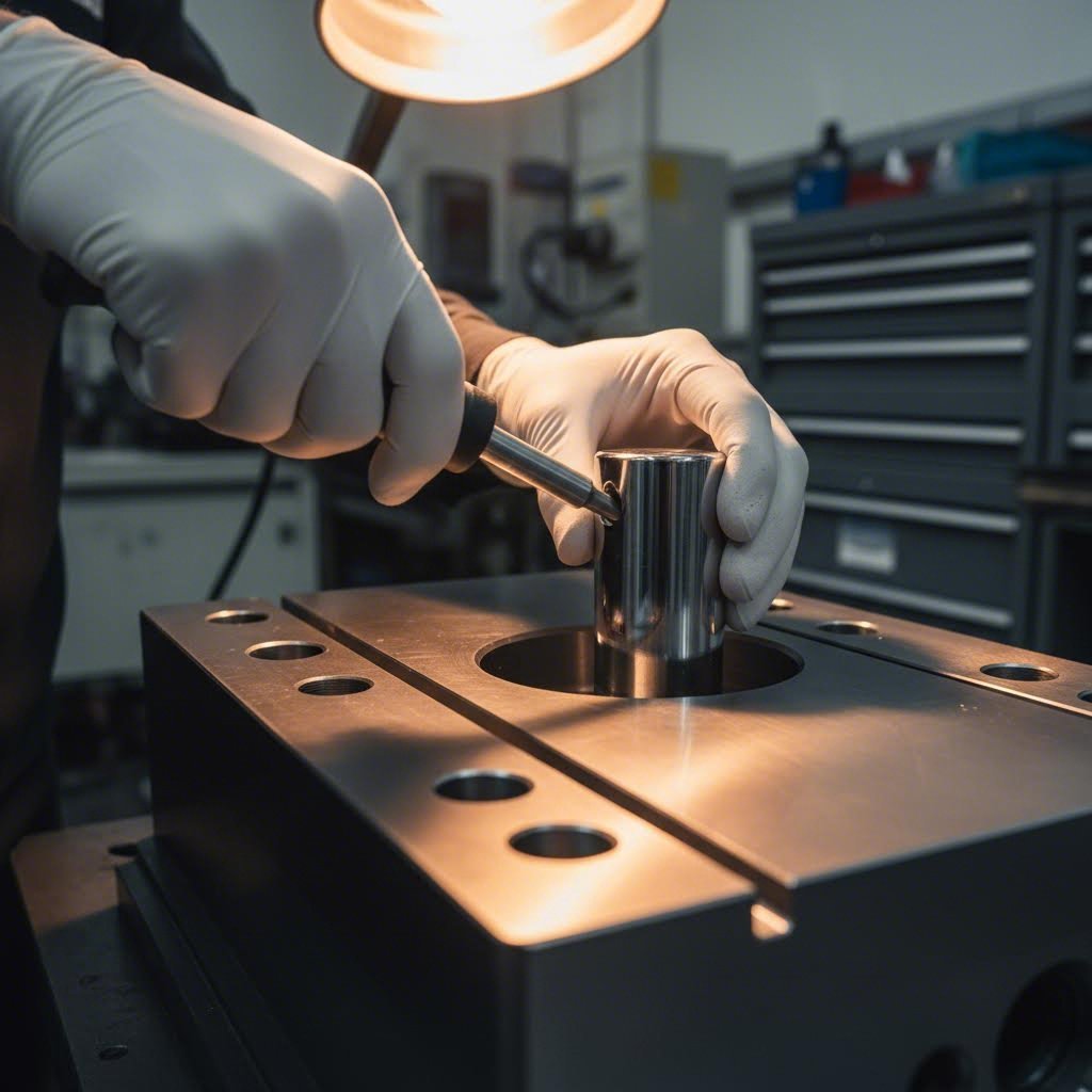
- Prepare the mounting bore: Machine the bore to manufacturer specifications, ensuring proper diameter, depth, and surface finish. Remove all chips, burrs, and contamination. A rough bore surface can damage the spring body during installation or operation.
- Verify spring condition before installation: Inspect the spring for shipping damage, confirm the model matches your specifications, and check that the rod moves smoothly through its full stroke. Never install a spring that shows signs of damage or contamination.
- Apply appropriate lubrication: If specified by the manufacturer, apply recommended lubricant to the bore and spring body. This facilitates installation and prevents galling between mating surfaces.
- Insert the spring with proper orientation: Most nitrogen springs can operate in any orientation, but some designs perform optimally in specific positions. Verify orientation requirements before proceeding. Lower the spring into the bore carefully, avoiding impacts that could damage seals or the rod surface.
- Secure mounting hardware to specification: Tighten retaining bolts or set screws to recommended torque values. Under-torqued fasteners allow movement during operation. Over-torqued fasteners can distort the spring body or mounting components.
- Verify rod alignment under load: Before running production, cycle the die slowly while observing rod movement. The rod should extend and retract smoothly without visible deflection or binding. Any irregularity indicates an alignment problem requiring correction.
- Document installation details: Record the installation date, spring model, initial pressure reading if accessible, and any observations. This documentation proves invaluable for maintenance scheduling and troubleshooting.
Mounting orientation deserves special attention. While nitrogen springs generally function in vertical, horizontal, or angled positions, some configurations perform best when mounted with the rod facing downward. This orientation helps internal lubrication reach critical seal surfaces. Check manufacturer guidelines from dadco inc or your specific supplier for orientation recommendations.
Safety Considerations for Pressurized Components
Never forget that you're handling components containing compressed gas at significant pressure. A nitrogen spring is essentially a pressure vessel, and treating it casually invites serious injury.
- Never attempt to disassemble a charged spring: These units are factory-sealed and not serviceable in the field. Attempting to open a pressurized spring can result in violent release of stored energy.
- Avoid impacts to the rod or body: Dropping a spring or striking it with tools can damage seals or create stress points that lead to failure under pressure.
- Keep faces and body clear during initial cycling: When testing a newly installed spring, position yourself away from the rod path. In the unlikely event of a seal failure, the rod could eject with considerable force.
- Store springs properly when not installed: Keep them in a clean, dry environment away from heat sources and corrosive materials. Protect the rod surface from scratches and contamination.
Proper installation directly impacts how many stroke cycles you'll achieve before replacement becomes necessary. Leading manufacturers warrant their products for specific cycle counts, often exceeding one million strokes under proper operating conditions. However, these warranties assume correct installation and operation within specified parameters. A spring that's misaligned or improperly mounted may fail at a fraction of its rated lifespan, voiding warranty coverage and disrupting your production schedule.
The time invested in careful installation pays dividends throughout the spring's service life. Beyond extending component longevity, proper mounting ensures the consistent force delivery that makes nitrogen gas springs so valuable in precision stamping. Your parts come out right, your tooling lasts longer, and your operation runs smoother.
Of course, even perfectly installed springs eventually require attention. Knowing how to recognize early warning signs of degradation and following appropriate maintenance protocols keeps your stamping operation running at peak performance.
Maintenance Protocols and Troubleshooting Common Issues
Your nitrogen gas springs are installed correctly and performing beautifully. But here's the reality: even the best components don't last forever. Understanding how gas spring technology works means recognizing that seals age, pressure gradually diminishes, and operating conditions take their toll over time. The difference between shops that maximize spring lifespan and those constantly replacing components comes down to proactive maintenance and early problem detection.
Think of maintenance as protecting your investment. A nitrogen gas spring rated for one to two million stroke cycles can deliver that full service life, but only when you catch small problems before they become catastrophic failures. Waiting until a spring fails during production means unplanned downtime, potential part quality issues, and emergency replacement costs that far exceed preventive maintenance expenses.
Recognizing Early Warning Signs of Spring Degradation
Every failing spring sends signals before it quits entirely. The challenge is knowing what to look for and checking regularly enough to catch these warnings. When you understand how a gas spring works internally, the failure modes make intuitive sense.
Seal degradation represents the most common failure path. The seals that contain high-pressure nitrogen and prevent contamination from entering the cylinder gradually wear with each stroke cycle. As they deteriorate, small amounts of gas escape, reducing internal pressure and force output. Watch for these indicators:
- Gradual force reduction: Parts that previously formed correctly now show slight wrinkling or incomplete features. The spring still functions but delivers less force than when new.
- Visible oil or residue around the rod: Internal lubricants escaping past worn seals leave telltale traces on the rod surface or surrounding die components.
- Slower rod return: When extended spring return becomes noticeably sluggish, internal pressure has likely dropped below optimal levels.
- Inconsistent cycle-to-cycle performance: Variations in part quality that weren't present before often indicate fluctuating spring force from seal issues.
Rod damage creates a secondary failure pathway. The precision-ground rod surface must remain smooth to seal properly against internal components. Scratches, scoring, or corrosion compromise this seal interface and accelerate gas loss. Inspect rods regularly for:
- Visible scratches or scoring: Even minor surface damage can allow gas to escape past seals during each stroke.
- Corrosion or pitting: Exposure to coolants, lubricants, or environmental contaminants attacks the rod surface over time.
- Discoloration or staining: Heat damage or chemical exposure may indicate operating conditions outside acceptable parameters.
- Bent or misaligned rods: Impact damage or side loading causes permanent deformation that prevents proper sealing.
Pressure loss without visible damage suggests internal seal failure or slow gas permeation through seals over extended periods. Some gas spring company products include pressure indicators or test ports that allow verification of internal pressure. When available, checking pressure during scheduled maintenance provides the most direct assessment of spring condition.
Preventive Maintenance Schedules That Extend Service Life
Reactive maintenance means you're already behind. Establishing regular inspection intervals catches degradation early and allows planned replacement during scheduled downtime rather than emergency stops during production runs.
Your maintenance frequency should reflect actual operating conditions. High-cycle operations running multiple shifts demand more frequent inspection than low-volume applications. Harsh environments with coolant exposure, metal particles, or temperature extremes accelerate wear and warrant closer monitoring.
Consider implementing this tiered inspection approach:
- Daily visual checks: Quick observation of rod condition, any visible leakage, and obvious damage during routine die inspection. Takes seconds but catches acute problems immediately.
- Weekly functional verification: Observe spring performance during operation. Note any changes in return speed, force consistency, or unusual sounds.
- Monthly detailed inspection: Clean rod surfaces and examine closely for scratches, corrosion, or wear patterns. Check mounting hardware for loosening. Verify alignment remains within specification.
- Quarterly performance assessment: If possible, measure actual force output and compare against baseline values recorded during installation. Document any degradation trends.
Cleaning practices significantly impact longevity. Metal chips, grinding dust, and dried lubricants accumulating around nitrogen gas struts act as abrasives that damage rod surfaces. Wipe rods clean with lint-free cloths during inspections. Avoid compressed air that might drive contaminants into seal areas.
Environmental protection extends service life considerably. When dies are stored between production runs, retract springs to their shortest position if possible. This minimizes exposed rod surface vulnerable to contamination or corrosion. Consider protective covers for long-term storage.
End-of-Life Indicators and Replacement Timing
Even with excellent maintenance, every spring eventually reaches the end of its useful service life. Recognizing when replacement is necessary prevents the false economy of running degraded components that compromise part quality or risk sudden failure.
Clear replacement triggers include:
- Force output drops below minimum requirements: When the spring can no longer deliver adequate force for your application, no amount of maintenance restores capacity. Recharging may extend life temporarily for some designs, but replacement is typically more reliable.
- Visible damage to critical surfaces: Significant rod scoring, body dents, or mounting surface damage compromises function and safety. Don't attempt to continue operating damaged pressure vessels.
- Approaching rated cycle life: If you track stroke counts and approach manufacturer-rated limits, proactive replacement during planned downtime prevents mid-production failures.
- Repeated pressure loss after recharging: Springs that lose pressure quickly after recharging have seal damage that will only worsen. Continued operation risks complete failure.
Quality nitrogen springs from reputable manufacturers typically deliver between one and two million stroke cycles under proper operating conditions. This expectation assumes correct installation, operation within specified parameters, and reasonable maintenance practices. Your actual results may exceed or fall short of these benchmarks depending on your specific application severity.
When tracking service life, consider implementing a spring log that records installation dates, inspection findings, any recharging performed, and eventual replacement dates. This historical data reveals patterns specific to your operation and helps optimize replacement timing. You might discover certain die positions consistently wear springs faster, indicating alignment or loading issues worth investigating.
Replacement should involve more than simply swapping components. Use the opportunity to inspect mounting bores for wear, verify alignment remains correct, and address any conditions that may have contributed to premature failure. A new spring installed into the same problematic conditions will simply fail again at the same rate.
Understanding maintenance requirements prepares you to maximize return on your nitrogen spring investment. But the value these components deliver varies across different manufacturing sectors, with some industries demanding even more from their stamping operations than others.
Industry Applications from Automotive to Aerospace Stamping
Different manufacturing sectors demand different things from their stamping operations. What works perfectly for appliance housings might fall short for automotive body panels, and aerospace components push requirements even further. Understanding how nitrogen gas springs address the unique challenges in each industry helps you evaluate whether these components match your specific production demands.
The consistent force delivery these springs provide translates into tangible benefits across sectors, but the reasons why that consistency matters vary considerably. Let's explore how leading manufacturers in automotive, appliance, and aerospace stamping leverage this technology to solve their distinct challenges.
Automotive Panel Stamping Requirements and Solutions
Imagine stamping a car door outer panel. You're forming complex compound curves from high-strength steel or aluminum, and the blank holder must control material flow precisely across every square inch of that large surface. Too much variation in holding force and you'll see wrinkles in low-pressure areas or splits where pressure concentrated too heavily.
Automotive body panel production represents one of the most demanding applications for nitrogen gas springs. These operations typically run at high cycle rates, often exceeding 15 strokes per minute, while maintaining tolerances measured in fractions of a millimeter. The springs must deliver consistent force shift after shift, day after day, across production runs that may span millions of parts.
A small nitrogen gas cylinder cluster strategically positioned around a blank holder can distribute force more evenly than a few large mechanical springs ever could. This distributed approach allows engineers to fine-tune holding pressure across different zones of complex panel geometries, applying more force where material tends to wrinkle and less where splits are the concern.
The thermal stability of nitrogen springs also matters in automotive stamping. As dies heat up during continuous production, force output remains predictable. Mechanical springs, by contrast, can lose temper and change characteristics as temperatures climb, introducing variables that affect part quality.
Precision Demands in Appliance and Aerospace Applications
Appliance component stamping operates at a different scale but faces its own challenges. Think about the exterior panels on refrigerators, washing machines, or ovens. These large, visible surfaces demand excellent cosmetic quality with no surface defects, waviness, or distortion. Consumers notice imperfections immediately.
Here, consistent blank holding force prevents the subtle variations that create visible surface defects. A mini gas spring arrangement providing uniform pressure across large panel surfaces helps manufacturers achieve the cosmetic standards that premium appliance brands require. The repeatability cycle after cycle ensures the first part of a production run matches the last.
Aerospace stamping pushes precision requirements to their limits. Components for aircraft structures must meet tolerances and material specifications that far exceed typical industrial standards. When you're forming titanium or specialized aluminum alloys into critical structural parts, there's zero tolerance for process variation.
The consistent force characteristics of nitrogen springs become essential when forming these challenging materials. Aerospace alloys often have narrower forming windows than conventional steels. Too little blank holder force and the material moves uncontrollably. Too much and you exceed material limits. The flat force curve these springs deliver keeps the process centered within that tight window throughout every stroke.
The following table compares key application requirements across these three major stamping sectors:
| Application Factor | Automotive Body Panels | Appliance Components | Aerospace Structures |
|---|---|---|---|
| Typical Cycle Rates | 10-20 strokes per minute | 8-15 strokes per minute | 5-12 strokes per minute |
| Force Range Demands | Medium to high | Low to medium | Medium to very high |
| Dimensional Tolerances | Tight (±0.5mm typical) | Moderate (±1.0mm typical) | Very tight (±0.25mm or less) |
| Surface Quality Priority | High (Class A surfaces) | Very high (cosmetic visible) | Moderate (function over appearance) |
| Material Challenges | High-strength steel, aluminum | Coated steel, stainless | Titanium, aerospace aluminum |
| Production Volumes | Very high (millions of parts) | High (hundreds of thousands) | Low to medium (thousands) |
| Spring Life Expectations | 1-2 million cycles minimum | 500,000-1 million cycles | Reliability over cycle count |
Notice how the priorities shift across industries. Automotive stamping demands springs that survive extremely high cycle counts while maintaining force consistency. Appliance manufacturing prioritizes cosmetic outcomes that require steady, even pressure distribution. Aerospace applications value precision and reliability above all else, accepting lower cycle rates in exchange for tighter process control.
The technical explanation for why consistent force improves part quality comes down to material behavior during forming. Sheet metal flows according to the forces acting upon it. When blank holder force varies unpredictably during a stroke, material flow becomes unpredictable. Consistent force means consistent flow, which means consistent parts.
This principle applies regardless of industry, but the consequences of variation differ. An automotive panel with slight inconsistencies might pass inspection but create fit problems during assembly. An appliance panel with the same variation might be rejected for visible surface defects. An aerospace component with any deviation outside tolerance gets scrapped entirely, representing significant material cost and production delays.
Understanding these industry-specific demands helps you evaluate whether nitrogen gas springs align with your particular manufacturing challenges. But selecting the right components is only part of the equation. Finding the right partners who understand precision die design ensures your springs perform optimally within dies engineered to leverage their capabilities.
Selecting the Right Components and Die Partners
You've explored the technology, compared alternatives, learned calculation methods, and understand maintenance requirements. Now comes the practical question: is integrating nitrogen gas springs the right move for your specific stamping operation? And if so, where do you get nitrogen gas that delivers reliable performance? Making these decisions requires honest evaluation of your current situation and careful consideration of your sourcing and partnership options.
The truth is, these springs aren't the answer for every stamping application. Understanding when they make sense and when alternative solutions might serve you better saves money and frustration. Let's work through a practical decision framework that helps you evaluate your operation objectively.
Evaluating Your Stamping Operation for Gas Spring Integration
Before you purchase nitrogen gas components, take a hard look at what your operation actually requires. The goal isn't to adopt technology for its own sake but to solve real problems and improve measurable outcomes.
Ask yourself these evaluation questions:
- Are you experiencing inconsistent part quality? If blank holding variations cause wrinkling, splitting, or dimensional inconsistencies, consistent force delivery could address the root cause.
- Do your current springs require frequent replacement? Operations burning through mechanical or polyurethane springs every few months often find nitrogen systems more economical despite higher initial cost.
- Is your production volume high enough to justify the investment? High-cycle applications benefit most from the durability and consistency these components provide.
- Do space constraints limit your current spring options? Compact and miniature nitrogen springs deliver substantial force from packages that fit where traditional options cannot.
- Are you forming challenging materials? High-strength steels, aluminum, and specialty alloys often require the precise force control these springs deliver.
- Does your application demand tight tolerances? When dimensional requirements leave no room for process variation, consistent force throughout the stroke becomes essential.
If you answered yes to several of these questions, nitrogen gas springs likely offer genuine advantages for your operation. However, the components themselves represent only half the equation. Where to purchase nitrogen gas springs matters significantly, but equally important is ensuring your die design properly accommodates and leverages their capabilities.
Partnering with Precision Die Specialists for Optimal Results
Here's something many engineers overlook: even premium nitrogen springs underperform when installed in poorly designed dies. The spring provides consistent force, but the die must translate that force effectively to the workpiece. Mounting locations, alignment precision, load distribution, and overall die construction determine whether you realize the full potential of your investment.
This is where die engineering expertise becomes critical. When evaluating where to purchase nitrogen components and who builds your tooling, consider these partnership criteria:
- Engineering simulation capabilities: Partners using CAE simulation can predict spring performance within the die before cutting steel, identifying potential issues and optimizing placement.
- Quality system certifications: IATF 16949 certification indicates automotive-grade quality management systems that ensure consistent, documented processes.
- Prototyping speed: Rapid prototyping capabilities allow faster iteration when integrating new spring configurations into die designs.
- First-pass success rates: High approval rates on initial tryouts indicate engineering teams that get designs right without extensive rework cycles.
- Application experience: Partners with extensive stamping die experience understand how spring selection affects forming outcomes across different applications.
For manufacturers seeking precision stamping die solutions that optimize nitrogen gas spring performance, Shaoyi's automotive stamping die capabilities exemplify the engineering depth that makes integration successful. Their IATF 16949 certification ensures quality management meets automotive industry standards, while advanced CAE simulation capabilities enable precise spring placement optimization before physical tooling begins.
What truly distinguishes capable die partners is their ability to move quickly without sacrificing quality. Shaoyi's rapid prototyping in as little as 5 days accelerates the development cycle, while their 93% first-pass approval rate demonstrates engineering teams that understand how all die components, including force delivery systems, work together to produce quality parts.
When you're ready to integrate nitrogen gas springs into your stamping operation, remember that component quality and die design quality are inseparable. The best springs in poorly designed tooling waste their potential, while well-engineered dies maximize return on your investment. Choose partners who understand both sides of this equation, and you'll achieve the consistent, high-quality results that make top die shops successful.
Frequently Asked Questions About Nitrogen Gas Springs in Stamping
1. What are nitrogen gas springs?
Nitrogen gas springs are self-contained force delivery systems consisting of a sealed cylinder filled with pressurized nitrogen gas. When force is applied to the piston rod, the nitrogen compresses and stores energy. Upon release, the expanding gas pushes the piston back, providing controlled and consistent force throughout the stroke cycle. In stamping dies, they're positioned between die plates to control blank holding, stripping, and forming operations with far greater consistency than mechanical springs.
2. How does a nitrogen spring work?
A nitrogen spring works by compressing inert nitrogen gas within a precision-machined cylinder. When the die closes, it pushes the piston rod down, compressing the nitrogen and storing energy. The sealed gas exerts pressure against the piston, providing consistent force throughout the working stroke. When the die opens, the compressed gas expands and returns the rod to its extended position. This design delivers near-constant force output regardless of position, making them ideal for precision stamping applications.
3. What is the purpose of a gas spring in stamping dies?
Gas springs serve multiple critical functions in stamping dies. They provide consistent blank holding force to control material flow during forming, preventing wrinkling and splitting. They deliver reliable stripping force to separate formed parts from punches and die components. They also enable cam return mechanisms and support various auxiliary die functions. Their consistent force delivery throughout the stroke cycle ensures repeatable part quality across millions of production cycles.
4. How long do nitrogen gas springs last in stamping applications?
Quality nitrogen gas springs typically deliver between one and two million stroke cycles when properly installed and maintained. Actual lifespan depends on operating conditions, cycle rates, alignment precision, and maintenance practices. High-speed operations or harsh environments may reduce service life, while proper installation, regular inspections, and appropriate operating parameters can help springs reach or exceed rated cycle counts. Tracking stroke counts and monitoring for early warning signs helps optimize replacement timing.
5. Why choose nitrogen gas springs over mechanical springs for stamping?
Nitrogen gas springs offer significant advantages over mechanical springs in precision stamping. They deliver near-constant force throughout the stroke, while mechanical springs vary force by 20% or more. They require less space for equivalent force output and last significantly longer under high-cycle conditions. Though initial costs are higher, the total cost of ownership often favors nitrogen systems due to reduced replacement frequency, improved part quality, and decreased downtime in high-volume production.