 Small batches, high standards. Our rapid prototyping service makes validation faster and easier —

Automotive Stamping Dies Exposed: From First Sketch To Final Part
What Are Automotive Stamping Dies and Why They Matter
Every vehicle on the road contains 300 to 500 stamped metal components. Door panels, hoods, brackets, clips, structural reinforcements—all of these started as flat sheets of automotive metal before being transformed into precise three-dimensional parts. The tools responsible for this transformation? Automotive stamping dies.
Think of stamping dies as highly engineered cookie cutters on an industrial scale. These precision tools use hundreds of tons of force to shape, cut, bend, and form sheet metal into exact specifications. When a stamping press closes, it applies immense pressure through custom-designed dies, producing finished components in seconds rather than minutes.
The Precision Tools Behind Every Vehicle Body Panel
Automotive stamping dies are specialized tooling systems engineered to transform flat metal sheets into complex vehicle components through controlled force and pressure. Unlike generic manufacturing tools, metal stamping dies must meet tolerances measured in microns—typically within ±0.001 to ±0.005 inches for critical safety components.
Why does this precision matter? A single defective bracket, clip, or connector can trigger recalls costing millions. Seat belt anchors, airbag housings, and brake components demand the tightest tolerances because vehicle safety depends on them. This makes stamping dies one of the most critical investments in automotive manufacturing.
Stamping dies enable mass production of identical parts with micron-level precision—a single press can stamp 20 to 200 components per minute while maintaining consistency across millions of production cycles.
From Flat Steel to Complex Components
The automotive stamping process relies on four core operations that work together through die assemblies:
- Blanking cuts the basic shape from the sheet metal
- Piercing creates holes and openings at precise locations
- Bending adds angles and curves for mounting brackets and structural reinforcements
- Drawing stretches the metal into deeper shapes like body panels and oil pan components
You might wonder: what is an aftermarket part, and how does it relate to stamping? Many replacement automotive components—whether OEM or aftermarket—are produced using the same stamping die technology that created the original parts. The quality of the die directly determines the quality of every part it produces.
In the sections ahead, we'll explore how these dies are designed, built, and maintained. You'll learn the differences between progressive, transfer, and compound dies, discover how engineers tackle challenges with high-strength steel and aluminum, and understand what separates exceptional die suppliers from the rest. Whether you're an engineer evaluating tooling options or a buyer seeking the right manufacturing partner, this guide covers the complete journey from first sketch to final part.
Essential Components of a Stamping Die Assembly
Ever wondered what's inside the tooling that shapes your vehicle's body panels? A stamping die might look like a massive block of steel from the outside, but crack it open and you'll find a sophisticated assembly of precision components working in perfect coordination. Each part serves a specific purpose, and the quality of these individual elements directly determines whether your finished parts meet automotive tolerance requirements—or end up as scrap.
Understanding stamping die components isn't just academic knowledge. When you're evaluating die tooling options or troubleshooting production issues, knowing how each piece functions helps you make smarter decisions and catch problems before they cascade into costly failures.
Upper and Lower Die Assemblies Explained
The die set forms the foundation of the entire stamping die assembly. Think of it as the skeleton that holds everything else in precise alignment while providing a stable mounting platform for the stamping press. Without a rigid, well-engineered die set, even the best cutting and forming components will produce inconsistent parts.
Die Shoes are the heavy base plates that make up the top and bottom halves of every stamping die set. The lower die shoe mounts to the press bed or bolster, while the upper die shoe attaches to the press slide or ram. These aren't just structural—they're precision-machined surfaces that must maintain flatness within thousandths of an inch to ensure even load distribution during operation.
When the die-stamping machine cycles, these shoes absorb and distribute forces that can exceed several hundred tons. Any flex or misalignment here translates directly into dimensional errors in your finished parts. That's why die shoes are typically manufactured from high-strength steel or cast iron, heat-treated for stability.
Guide Pins and Bushings serve as the joints that keep upper and lower assemblies in perfect alignment throughout each press stroke. Hardened, precision-ground pins mounted on one die shoe slide into equally precise bushings on the opposing shoe. This system maintains consistent alignment even after millions of cycles.
The tolerance relationship matters here: guide pins and bushings typically maintain alignment within 0.0002 to 0.0005 inches. When these components wear or become contaminated with debris, you'll notice it immediately in part quality—misaligned holes, inconsistent trim lines, and accelerated wear on cutting components.
Critical Wear Components and Their Functions
While the die set provides structure, the working components do the actual forming and cutting. These parts contact the workpiece directly, enduring the greatest stresses, friction, and wear. Their design, material selection, and maintenance determine both part quality and die lifespan.
Punches are the male components that perform piercing, blanking, and forming operations. In automotive applications, punch geometry must be precise—a worn punch produces burrs, oversized holes, and dimensional drift that can fail inspection. Steel stamping dies for high-volume production typically use punches made from tool steel grades like D2, M2, or tungsten carbide for maximum wear resistance.
Die Blocks work as the female counterpart to punches in cutting operations. The die block contains precision-ground openings that match the punch profile with carefully calculated clearance—typically 5% to 10% of material thickness for automotive sheet steel. This clearance relationship is critical: too tight and you'll see excessive force and wear; too loose and burrs become unacceptable.
Strippers solve a problem you might not immediately consider. After a punch pierces material, the metal's elasticity causes it to grip the punch tightly. The stripper plate pushes material off the punch as it retracts, preventing jams and ensuring consistent feeding. Spring-loaded strippers also help control the workpiece during forming operations, improving surface quality.
Pressure Pads and Blank Holders control material flow during drawing and forming operations. Imagine pulling a tablecloth through a ring—without controlled resistance, it bunches and wrinkles. Pressure pads apply calibrated force to hold material flat while allowing controlled movement, preventing wrinkles in deep-drawn automotive panels.
Pilots ensure precise positioning of the strip or blank before each stamping operation. In progressive dies, pilots enter previously pierced holes to locate the material exactly where it needs to be for the next station. Without accurate piloting, cumulative positioning errors make multi-station operations impossible.
| Component | Primary Function | Typical Materials | Automotive Quality Impact |
|---|---|---|---|
| Die Shoes (Upper/Lower) | Structural foundation and press mounting | Cast iron, tool steel, alloy steel | Dimensional stability across production runs |
| Guide Pins & Bushings | Alignment between die halves | Hardened steel, bronze bushings | Consistent hole alignment, reduced wear |
| Punches | Piercing, blanking, and forming | D2, M2, A2 tool steel, tungsten carbide | Burr control, hole accuracy, edge quality |
| Die Blocks | Female cutting/forming surfaces | D2, A2, powder metallurgy steels | Part dimensional accuracy, surface finish |
| Strippers | Material removal from punches | Tool steel, spring steel | Consistent feeding, surface quality |
| Pressure Pads | Material flow control during forming | Tool steel, cast iron | Wrinkle prevention, uniform thickness |
| Pilots | Strip positioning and registration | Hardened tool steel | Multi-station accuracy, consistent features |
The relationship between component quality and final part precision cannot be overstated. Automotive industry tolerance requirements often demand positional accuracy within ±0.1mm and surface finishes that meet stringent appearance standards. A small error of a few micrometers in one component can trigger a chain reaction—wrong part dimensions, accelerated tool wear, increased scrap rates, and expensive unscheduled downtime.
When engineers specify a complete stamping die set, they're not just ordering parts—they're investing in an integrated system where every component must perform together. Understanding how each element contributes to the whole helps you evaluate suppliers, troubleshoot production issues, and make informed decisions about maintenance and replacement strategies. With this foundation in place, we can now explore how different die types—progressive, transfer, and compound—apply these components for specific automotive applications.
Progressive vs Transfer vs Compound Dies for Automotive Parts
You've got a new automotive component to manufacture. Maybe it's a small bracket, a large door panel, or something in between. How do you decide which die type will deliver the best results? This decision shapes everything from production speed to tooling investment—and getting it wrong can mean costly redesigns or missed quality targets.
The variety of die and stamping options available can feel overwhelming at first. Progressive dies, transfer dies, compound dies, tandem dies—each serves specific purposes in the automotive parts market. Understanding which die type matches your component requirements is one of the most important decisions you'll make before production begins.
Progressive Dies for High-Volume Small Parts
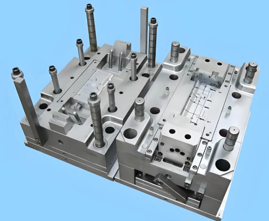
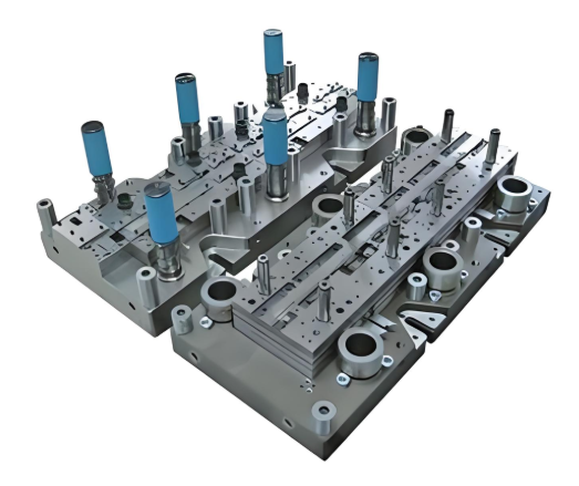
Imagine a continuous metal strip moving through a series of stations, with each station performing a specific operation—cutting, bending, forming—until a finished part drops off the end. That's die stamping in its most efficient form: the progressive die.
Progressive stamped automotive parts include brackets, clips, connectors, terminals, and small structural reinforcements. These components share common characteristics: relatively small size, moderate complexity, and high production volumes. A single progressive die can stamp 20 to 200 parts per minute, making it the go-to choice when you need millions of identical pieces.
Why does this approach work so well for smaller parts? The continuous strip feeding eliminates handling time between operations. Material moves automatically from station to station, and multiple parts can be nested within the strip width to maximize material usage. For stamper automotive operations focused on cost efficiency, progressive dies deliver the lowest per-piece cost at high volumes.
However, progressive dies have limitations. Part size is constrained by strip width and press capacity. Deep draws become difficult because the part remains attached to the carrier strip throughout processing. And the initial tooling investment is substantial—these dies are complex, precision-engineered systems that require significant upfront capital.
Transfer Dies for Large Structural Components
What happens when your part is too large for strip feeding, or requires deep draws that progressive dies can't handle? This is where transfer dies excel.
Transfer die stamping uses mechanical or hydraulic systems to move individual blanks between stations. Each station performs a specific operation—drawing, trimming, piercing, flanging—before the blank transfers to the next. Unlike progressive dies, the workpiece is completely separated from the strip before forming begins.
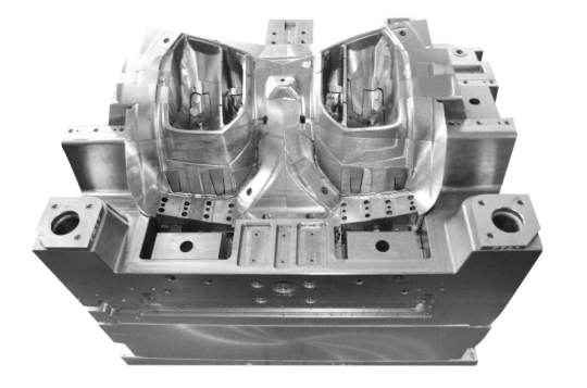
Automotive stamping parts produced with transfer dies include door outers, hoods, fenders, roof panels, and large structural components. These parts require deep draws, complex geometries, and precise dimensional control that progressive stamping cannot achieve. The stop-and-position nature of transfer operations allows for greater control over material flow during each forming step.
Transfer dies also offer a material efficiency advantage. According to industry data from Die-Matic Corporation, the transfer process utilizes less material than progressive stamping because blanks can be optimized for the specific part geometry. Since more than half of stamping cost is material, this efficiency translates directly into lower per-piece pricing for large components.
The tradeoff? Transfer die systems run slower than progressive operations due to the handling time between stations. They're best suited for medium to high volumes where the complexity requirements justify the additional cycle time.
Compound and Tandem Dies: Specialized Solutions
Not every automotive component fits neatly into the progressive or transfer category. Compound dies and tandem line configurations fill important gaps in the stamping toolkit.
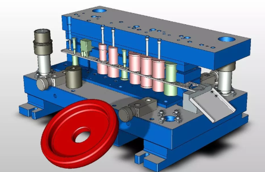
Compound dies perform multiple operations in a single stroke—cutting, bending, and forming all happen simultaneously. This integration reduces production time dramatically for medium-volume parts with moderate complexity. Think washers, simple brackets, or flat components that need cutting and forming but don't require multiple sequential stations.
The simplicity of compound dies makes them cost-effective for lower volumes where progressive tooling isn't justified. They're faster to build, easier to maintain, and require less press capacity than multi-station alternatives.
Tandem die lines take a different approach. Instead of integrating operations into one die, tandem setups use multiple presses arranged in sequence, each with a dedicated die for a specific operation. Large body panels like the Tesla Model Y hood follow this pattern: drawing forms the main shape, trimming cuts the outer edge, piercing adds mounting holes, and flanging bends edges for assembly.
Tandem configurations offer flexibility that integrated dies cannot match. Individual dies can be modified or replaced without rebuilding the entire tooling system. For complex panels requiring five or more distinct operations, this modular approach often makes more sense than attempting to combine everything into a single massive die.
Matching Die Types to Automotive Applications
Selecting the right die type comes down to matching your specific requirements against each technology's strengths. Here's how the options compare across key decision criteria:
| Die Type | Typical Automotive Applications | Production Volume | Part Size Range | Complexity Capability | Relative Tooling Investment |
|---|---|---|---|---|---|
| Progressive | Brackets, clips, connectors, terminals, small reinforcements | High (500K+ annually) | Small to medium | Moderate (limited draw depth) | High initial, low per-piece |
| Transfer | Door panels, hoods, fenders, structural components | Medium to high (100K-1M+) | Medium to large | High (deep draws, complex geometry) | High initial, moderate per-piece |
| Compound | Washers, simple brackets, flat stamped components | Low to medium (10K-250K) | Small to medium | Low to moderate | Moderate |
| Tandem Line | Large body panels, complex assemblies requiring multiple operations | Medium to high (100K-500K+) | Large | Very high (multi-stage forming) | Very high (multiple dies) |
When Hybrid Approaches Make Sense
Sometimes the best solution isn't a single die type but a combination. Hybrid approaches emerge when parts have characteristics that span multiple categories.
Consider a medium-sized structural bracket with deep-drawn features and multiple pierced holes. A progressive die might handle the piercing efficiently, but the draw depth exceeds strip-fed limitations. The solution? A transfer-progressive hybrid that uses transfer handling for the drawing operation, then feeds the partially formed part into progressive stations for subsequent operations.
Other hybrid scenarios include:
- Progressive roughing with transfer finishing—initial forming in high-speed progressive stations, followed by precision transfer operations for final geometry
- Tandem lines with integrated progressive stations—large panel forming in tandem presses, with small attached features produced in progressive sub-dies
- Compound dies within transfer systems—combining multiple simple operations at individual transfer stations to reduce total station count
The decision framework should start with your part's specific requirements: size, complexity, production volume, and tolerance demands. From there, evaluate which die type—or combination—delivers the best balance of quality, speed, and total cost. With the right die selection established, the next critical phase is translating your part design into production-ready tooling through the die design and engineering process.
The Die Design Process from Concept to Production
You've selected the right die type for your automotive component. Now what? Before any steel gets cut, your part design must travel through a rigorous engineering process that transforms a CAD model into production-ready tooling. This journey from concept to validated auto die is where success or failure is determined—long before the first press stroke.
Here's the reality: rushing through die design to save time upfront almost always costs more in the end. Physical tryouts, rework, and production delays can consume weeks and hundreds of thousands of dollars. That's why leading stamping die manufacturers invest heavily in simulation-driven design processes that catch problems virtually before they become expensive physical realities.
The Five Stages of Automotive Stamping Die Development
The automotive metal stamping process for die development follows a structured progression. Each stage builds on the previous one, moving from high-level feasibility to the precise detail engineering that guides manufacturing. Skipping steps or rushing through analysis introduces risk that compounds as the project advances.
Stage 1: Feasibility Analysis
Before any design work begins, engineers must answer a fundamental question: can this part actually be stamped? Feasibility analysis examines the part geometry, material specifications, and tolerance requirements to determine if stamping is the right manufacturing approach—and if so, what challenges to expect.
This gatekeeping process identifies potential showstoppers early. Deep draws that exceed material formability limits, complex geometries that require expensive multi-station tooling, or tight tolerances that demand specialized processes all surface during feasibility review. According to U-Need Precision Manufacturing, this first analysis directly affects four key factors: part quality, production cost, manufacturing efficiency, and tooling longevity.
Stage 2: Strip Layout and Process Planning
For progressive and transfer dies, the strip layout defines the sequence of operations that transform flat metal into finished parts. This blueprint determines how cutting, forming, and finishing operations are arranged—and it's where material efficiency is won or lost.
Engineers balance competing priorities during strip layout development: minimizing material waste, ensuring adequate progression between stations, maintaining strip stability, and optimizing production speed. A well-designed layout can reduce scrap by 10% to 15% compared to a naive approach, translating directly into lower per-piece costs across high-volume production runs.
Stage 3: Die Face Development
The die face is where engineering gets complex. Designing a stamping die isn't as simple as creating a negative of the part geometry—that approach would produce splits, wrinkles, and dimensional failures on the first hit.
Stage 4: Structural Design
With the die face geometry established, attention turns to the physical structure that will support it. This includes die shoe sizing, guide system specification, and the mechanical details that ensure the die survives millions of production cycles.
Stage 5: Detail Engineering
The final stage produces complete manufacturing documentation: 3D models, 2D drawings, tolerances, material specifications, and assembly instructions for every component. This package guides the machining, grinding, and EDM operations that transform raw steel into precision tooling.
CAE Simulation in Modern Die Development
Imagine knowing exactly where your stamped panel will crack, wrinkle, or spring back out of tolerance—before you've spent a dollar on tooling steel. That's the power of Computer-Aided Engineering simulation in automotive stamping die development.
Modern CAE platforms like AutoForm, DYNAFORM, and ESI PAM-STAMP use finite element analysis to model the complete forming process digitally. Engineers input part geometry, tool surfaces, material properties, and process parameters. The software calculates stresses, strains, material flow, and thickness distribution throughout every millisecond of the forming operation.
What can simulation predict?
- Splits and cracks—areas where material stretches beyond its forming limits
- Wrinkles and surface defects—regions of excessive compression that create cosmetic failures
- Thinning distribution—thickness variations that affect structural integrity
- Springback behavior—elastic recovery that throws dimensions out of specification
- Forming forces—press tonnage requirements for equipment selection
According to AutoForm, forming simulation has become standard practice in automotive manufacturing because it enables engineers to detect errors on the computer at an early stage. The result? Fewer physical tool tryouts, shorter development cycles, and dramatically higher first-time success rates.
The iterative nature of simulation-driven design is key. Engineers run an initial simulation, identify problem areas, modify the die face or process parameters, and simulate again. This virtual iteration loop is far cheaper and faster than the alternative: building physical tooling, running tryouts, identifying failures, re-machining hardened steel, and repeating until the die finally works.
From Part Geometry to Die Face Design
The die face design challenge is often underestimated. Creating tooling surfaces that produce accurate parts requires accounting for material behavior that isn't intuitive—especially springback compensation.
When sheet metal is formed, it stretches and bends. Remove the forming forces, and the material's elasticity causes partial recovery toward its original flat state. For automotive panels, this springback can measure several millimeters—far exceeding typical tolerance requirements. Engineers must design die faces that intentionally overbend the material so it springs back to the correct final geometry.
According to ESI Group's die face design research, modern tools like Die Starter can create an optimized die face geometry in minutes rather than days. The software uses an advanced solver to automatically adjust binder shape, addendum geometry, and drawbead restraining forces—achieving feasible forming with minimal material consumption.
Beyond the part geometry itself, die face design must incorporate:
- Addendum surfaces—extensions beyond the part boundary that control material flow during forming
- Binder geometry—surfaces that clamp the blank edges and regulate draw-in
- Drawbeads—raised features that create controlled resistance to material movement
These additions guide the stretching and forming of sheet metal into the correct shape. The excess material held by addendums and binders is trimmed away in subsequent operations, leaving only the final part geometry.
Key Design Considerations for Automotive Stamping Dies
Every automotive stamping die project involves trade-offs between competing requirements. The best designs optimize across multiple factors simultaneously:
- Material grade and thickness—different steel grades and aluminum alloys have vastly different formability characteristics; die design must account for specific material behavior
- Draw depth requirements—deeper draws demand more sophisticated die face geometry, larger blanks, and careful control of material flow
- Blank size optimization—minimizing blank size reduces material cost, but too-small blanks cause edge cracking and inconsistent forming
- Scrap reduction strategies—nesting optimization, carrier strip design, and blank shape development all contribute to material efficiency
- Automotive part marking requirements—identification features must be integrated into die design for traceability without compromising part quality
- Tolerance stack-up management—cumulative errors across multi-station operations must stay within final part specifications
Stamping manufacturing economics make these considerations critical. Material typically represents more than half of total part cost in high-volume production. A die design that reduces blank size by just 5% can translate into significant savings across millions of parts. Similarly, reducing physical tryout iterations through simulation-validated designs cuts weeks from development timelines and avoids expensive rework cycles.
The engineering investment in proper die design pays dividends throughout the tooling lifecycle. A well-designed die produces consistent parts from the first hit, requires less maintenance, and lasts longer in production. With the design process complete and validated through simulation, the next challenge emerges: adapting these principles to the advanced materials driving automotive lightweighting trends.

Stamping Challenges with Advanced Automotive Materials
Here's a scenario every automotive engineer faces today: your OEM customer demands lighter vehicles for better fuel efficiency and extended EV range. The solution seems straightforward—switch from conventional mild steel to advanced high-strength steel or aluminum. But when your existing dies hit these new materials, everything changes. Parts spring back out of tolerance. Forming forces spike beyond press capacity. Die surfaces wear at alarming rates. What worked perfectly for decades suddenly fails.
This isn't a hypothetical problem. The automotive industry's push toward lightweighting has fundamentally altered the demands placed on sheet metal stamping dies. Understanding these challenges—and the die design adaptations that solve them—separates successful automotive metal stamping operations from those struggling with scrap rates and production delays.
Conquering Springback in High-Strength Steel Stamping
Springback is the tendency of formed metal to partially return toward its original flat shape after the forming load is removed. Every sheet metal material exhibits some springback, but with advanced high-strength steels, the problem intensifies dramatically.
Why does this happen? According to FormingWorld's analysis of springback behavior, the physics is straightforward: springback is proportional to forming stress divided by elastic modulus. When you double the yield strength of a material, you effectively double its springback potential. AHSS grades with yield strengths approaching 600 MPa—three times higher than conventional mild steel—create proportionally greater elastic recovery after forming.
The math gets worse for aluminum. With an elastic modulus of approximately 70 GPa compared to steel's 200 GPa, aluminum exhibits roughly three times the springback effect at equivalent stress levels. For automotive metal stamping parts requiring tight dimensional tolerances, this represents a fundamental engineering challenge.
What makes springback particularly difficult to manage? Real automotive panels don't experience uniform strain distribution. Different areas on the same part undergo different deformation levels, creating complex springback patterns that vary from region to region. A door panel might spring back differently at the window opening than at the hinge mounting area—and these variations can change from part to part during normal production conditions.
Die designers combat springback through several compensation strategies:
- Over-bending compensation—die surfaces are designed to bend material beyond the target angle so it springs back to the correct final geometry
- Stress redistribution—addendum and binder geometries are optimized to create more uniform strain distribution across the panel
- Drawbead optimization—restraining features are calibrated to control material flow and reduce springback variation
- Multi-step forming sequences—complex geometries are formed progressively to manage accumulated elastic strain
Modern CAE simulation makes springback compensation practical by predicting elastic recovery before tooling is cut. Engineers iterate through virtual designs, adjusting die faces until simulated parts fall within tolerance after springback. Without simulation, steel stampings from AHSS would require numerous expensive physical tryout cycles to achieve dimensional accuracy.
Aluminum Forming Challenges and Die Solutions
Aluminum presents a different set of challenges beyond its pronounced springback behavior. The material's lower formability limits, tendency toward galling, and thermal sensitivity all demand specialized die design approaches.
Unlike steel, aluminum has a narrower forming window. Push the material too far and it cracks without the gradual necking that provides warning in steel forming. This reduced formability margin means automotive sheet steel designs cannot simply be transferred to aluminum—geometries must be re-evaluated, and sometimes simplified, to accommodate the material's limitations.
Galling—the adhesive wear mechanism where aluminum transfers onto die surfaces—creates both quality and maintenance problems. According to JEELIX's forming die selection guide, aluminum forming often requires specialized lubricants and die coatings to combat this tendency. PVD and CVD coatings serve as genuine performance amplifiers, dramatically extending die life when forming aluminum automotive components.
Material-specific considerations for aluminum die design include:
- Increased die clearances—aluminum's lower strength and greater elastic recovery require adjusted punch-to-die relationships
- Surface finish requirements—smoother die surfaces reduce friction and galling tendency
- Coating selection—DLC (diamond-like carbon) and other advanced coatings prevent aluminum adhesion
- Temperature management—warm forming processes can improve aluminum formability for complex geometries
- Lubrication systems—specialized lubricants designed for aluminum forming are essential, not optional
Die Adaptations for AHSS Production
Advanced high-strength steels impose extreme demands on die materials and construction. Tensile strengths exceeding 1500 MPa in press-hardened grades generate forming forces two to three times greater than mild steel. This creates challenges that go beyond simple capacity calculations.
Conventional tool steels like D2, which perform adequately for mild steel stamping, suffer rapid wear and potential surface damage when processing AHSS. The extreme contact pressures can cause permanent indentation of die surfaces, destroying dimensional accuracy. According to JEELIX's research, AHSS inflicts a dual assault on dies—combining abrasive wear from hard microstructural phases with adhesive wear from the intense pressures and temperatures generated during forming.
Successful metal stampings for automotive components in AHSS require upgraded tooling approaches:
- Powder metallurgy tool steels—PM grades like Vanadis and CPM series offer superior wear resistance with the toughness to resist chipping under AHSS impact loads
- Tungsten carbide inserts—strategic placement in high-wear zones like draw beads and forming radii extends overall die life
- Advanced surface treatments—PVD coatings reduce friction and combat the adhesive wear mechanisms AHSS promotes
- Modified clearances—tighter control of punch-to-die gaps compensates for AHSS's reduced edge stretch tolerance
Connecting to Automotive Lightweighting Trends
These material challenges aren't going away—they're intensifying. The automotive industry's commitment to lightweighting for fuel efficiency and EV range optimization continues to drive adoption of AHSS and aluminum across vehicle platforms. Body-in-white weight reductions of 20% to 30% are common targets, achievable only through strategic material substitution.
For stamping operations, this means sheet metal stamping dies must evolve alongside the materials they form. The investments in simulation capabilities, advanced die materials, and specialized coatings represent the cost of remaining competitive in automotive supply chains. Organizations that master these challenges gain significant advantages; those that don't face mounting quality issues and shrinking margins.
With material challenges understood, the next critical phase focuses on what happens after die construction: the tryout and validation processes that confirm production readiness before parts reach assembly lines.
Die Tryout and Validation Before Production
Your stamping die has been designed, simulated, and machined to exacting specifications. The tooling investment runs into six or seven figures. But here's the uncomfortable truth: until that die produces actual parts under production conditions, everything remains theoretical. The die tryout and validation process bridges the gap between engineering intent and manufacturing reality—and it's where many programs either succeed or stumble into costly delays.
This phase receives surprisingly little attention in industry discussions, yet it directly determines whether your stamping dies manufacturer delivered production-ready tooling or an expensive starting point for months of adjustments. Understanding what happens between die construction and production release helps you set realistic expectations, evaluate supplier capabilities, and avoid the hidden costs of inadequate validation.
Die Tryout Protocols for First-Time Quality
Think of die tryout as the moment of truth for every engineering decision made during design. The press closes, metal flows into die cavities, and physics reveals whether simulations matched reality. First-time quality—producing acceptable parts without extensive rework—separates excellent automotive stamping companies from those that struggle with extended development cycles.
Initial tryout typically occurs at the die builder's facility using a tryout press matched to the intended production equipment. According to Adient's 2025 North American Die Standards, the tool vendor must run dies at defined strokes per minute for a 300-hit run, demonstrating both part quality and mechanical reliability before the tooling ships to the production facility.
What happens during those critical first hits? Engineers watch for immediate failure modes:
- Splits and cracks—material stretched beyond forming limits, indicating die face geometry or blank size problems
- Wrinkles and overlaps—excessive material compression from inadequate blank holder pressure or improper draw bead restraint
- Surface defects—scratches, galling marks, or orange peel texture that fail appearance standards
- Dimensional deviations—springback, twist, or profile errors that exceed tolerance specifications
Metal parts stamping at production speeds reveals dynamic behaviors that slower tryout strokes miss. Strip feeding stability, scrap ejection reliability, and thermal effects from continuous operation all surface during extended tryout runs. The goal isn't just making one good part—it's demonstrating the die can produce thousands of consistent parts hour after hour.
Panel Quality Evaluation and Die Spotting
Even when initial parts look acceptable, detailed inspection often reveals issues invisible to the naked eye. Panel quality evaluation uses multiple techniques to assess whether formed components meet automotive specifications.
Visual inspection catches obvious surface defects, but trained evaluators also use techniques like oilstoning—lightly sanding panels with oilstone to highlight subtle surface waves, low spots, and die marks. For Class A exterior surfaces on hoods and doors, even minor imperfections rejected by oilstone inspection require correction.
Die spotting is the art of adjusting contact between die surfaces and formed material. Using Prussian blue dye or similar marking compounds, toolmakers identify where steel contacts material and where gaps exist. Skilled die spotters then hand-grind and polish die surfaces until contact is uniform across critical forming and trim areas. This labor-intensive process directly affects part quality and die longevity.
According to the Adient standards, any form or cutting steels welded during die development must be replaced before final buy-off. This requirement reflects a critical quality principle: welded repairs are acceptable for development iterations, but production tooling must use solid, properly heat-treated components that maintain dimensional stability across millions of cycles.
Validation Standards for Production Release
Production validation goes beyond making good parts—it demonstrates the die meets rigorous quality system requirements that govern automotive manufacturing. For plating stamped components and other critical parts, this validation provides documented evidence that the process is capable and controlled.
Dimensional validation relies heavily on two complementary technologies:
Checking fixtures are custom-built gauges that verify parts fit assembly requirements. Stamped panels are placed on the fixture, and inspectors verify that locating points, mounting surfaces, and critical features align within tolerance. According to Adient's buy-off requirements, parts must pass the attribute gage 100%—no exceptions for production approval.
Coordinate Measuring Machine (CMM) layouts provide precise dimensional data across dozens or hundreds of measurement points. CMM inspection quantifies exactly how formed parts compare to nominal CAD geometry, identifying both average deviations and variation between parts. The Adient standard requires six-piece dimensional CMM layouts per the quality measurement plan, with parts restrained on datums matching the attribute check fixture.
A minimum Cpk of 1.67 must be achieved on a 30-piece sample for all safety-critical and customer-critical dimensions identified on the drawing.
This statistical capability requirement ensures the process produces parts well within specification, not just barely acceptable. A Cpk of 1.67 means the process average is at least five standard deviations from the nearest specification limit—providing substantial margin against normal variation.
The Sequential Validation Journey
From initial tryout through production approval, validation follows a structured progression. Each stage builds confidence that the die will perform reliably in high-volume manufacturing:
- Soft tool tryout—initial forming trials using preliminary tooling to verify basic die function and identify major forming issues before hardening
- Hard tool tryout at die builder—production-intent tooling runs 300-piece continuous operation, demonstrating mechanical reliability and producing sample parts for initial dimensional evaluation
- Six-piece dimensional layout approval—CMM data confirms parts meet specification; approval required before scheduling production facility buy-off
- Production facility installation—die installed in intended production press with all auxiliary equipment (feeders, conveyors, sensors)
- 90-minute production run—continuous operation at production rate in full automatic mode, demonstrating sustained capability
- 30-piece capability study—statistical validation confirming process meets Cpk requirements for critical dimensions
- Final buy-off and documentation—completed buy-off checklist, updated CAD models, and all design documentation submitted for production release
This progression typically spans several weeks, with iteration loops when issues arise. According to industry experience, dies are warranted for craftsmanship and production capability for a minimum of 50,000 strokes run in full automatic mode—providing assurance that initial quality will be maintained.
IATF 16949 and Quality System Requirements
Automotive stamping operations don't exist in isolation—they function within rigorous quality management systems. IATF 16949 certification represents the baseline quality standard for automotive suppliers, and its requirements directly influence die validation processes.
The standard mandates Statistical Process Control (SPC) for monitoring key characteristics during production. According to industry guidance on IATF 16949 core tools, SPC uses control charts to detect variability and spot trends before they produce defective parts. For stamped components, this means continuous monitoring of critical dimensions, with defined reaction plans when measurements approach control limits.
When evaluating who offers the best quality in automotive aftermarket or OEM supply chains, IATF 16949 certification provides essential assurance. Certified suppliers maintain documented quality systems covering Advanced Product Quality Planning (APQP), Production Part Approval Process (PPAP), Failure Mode and Effects Analysis (FMEA), and Measurement System Analysis (MSA)—all of which touch die validation activities.
Even the best aftermarket auto parts brands rely on these same validation principles. Whether producing original equipment or replacement components, the stamping process must demonstrate controlled, capable production that delivers consistent quality part after part.
The investment in proper die tryout and validation pays dividends throughout production life. Dies released with thorough validation produce fewer defects, require less unplanned maintenance, and meet delivery schedules reliably. Those rushed into production without complete validation become ongoing problems—consuming engineering resources, generating scrap, and straining customer relationships. With validation complete and production approved, attention shifts to maintaining die performance across the millions of cycles ahead.
Die Maintenance and Lifespan Optimization
Your stamping die passed validation with flying colors. Production launched smoothly, and parts are flowing to assembly lines on schedule. But here's what many operations overlook: that expensive tooling investment is now on a countdown. Every press stroke creates wear. Every production run accumulates stress. Without systematic maintenance, even the best-designed stamping tooling degrades until quality failures force expensive emergency repairs—or worse, unplanned production shutdowns.
Die maintenance isn't glamorous work, but it's the difference between tooling that delivers millions of consistent parts and tooling that becomes a constant source of quality escapes and firefighting. According to The Phoenix Group's analysis of die shop management, a poorly defined maintenance system can dramatically decrease press line productivity and increase costs through quality defects, scrap, and unscheduled downtime.
Preventive Maintenance Schedules for Production Dies
Think of preventive maintenance as insurance against catastrophic failure. Regular inspections catch developing problems before they escalate into production-stopping emergencies. The alternative? Waiting until parts show burrs, tolerances drift out of spec, or you hear concerning noises from your die stamping machine—by which point you're already shipping suspect quality and facing expensive repairs.
Effective preventive maintenance starts with structured inspection protocols. According to industry best practices for tool and die maintenance, regular visual examinations should check for cracks, chips, or deformations on working surfaces and edges. Using magnifying tools helps spot minor defects that could impact part quality before they become major issues.
What should you inspect, and how often? The answer depends on production volume, material being formed, and component criticality. High-volume industrial stamping operations running AHSS might require daily inspections, while lower-volume runs with mild steel could extend to weekly checks. The key is establishing consistent intervals based on your specific conditions.
Common indicators that signal needed repairs include:
- Burrs on stamped parts—worn cutting edges no longer shear cleanly
- Dimensional drift—tolerances gradually moving toward specification limits
- Increased tonnage requirements—worn or galled surfaces creating additional friction
- Unusual sounds during operation—potential misalignment or component damage
- Surface defects on formed panels—die surface wear transferring to parts
According to Wisconsin Metal Parts' maintenance guidance, keeping the last part from each production run along with the end strip helps toolmakers investigate and zero in on problem areas. Each die leaves clues about what's happening—a skilled tool and die maker can decipher those clues and tell that tool's story.
| Die Component | Inspection Interval | Typical Maintenance Actions | Warning Signs |
|---|---|---|---|
| Cutting Punches | Every 10,000-50,000 strokes | Sharpen edges, check for chipping, verify dimensions | Burrs on parts, increased cutting force |
| Die Buttons/Blocks | Every 25,000-75,000 strokes | Inspect clearances, regrind cutting edges, replace worn inserts | Slug pulling, inconsistent hole quality |
| Guide Pins & Bushings | Weekly or every 50,000 strokes | Clean, lubricate, check for wear and scoring | Misaligned features, accelerated component wear |
| Springs | Monthly or per PM schedule | Check tension, replace fatigued springs | Inconsistent stripping, feeding problems |
| Forming Surfaces | Every production run | Clean, inspect for galling, apply lubricant | Surface defects on panels, scoring marks |
| Pilots | Every 25,000-50,000 strokes | Check for wear, verify positioning accuracy | Cumulative positioning errors, mislocated features |
When to Refurbish vs Replace Worn Tooling
Every worn die presents a decision: repair it, refurbish it, or replace it entirely? The right choice depends on the extent of wear, remaining production requirements, and the economics of each option. Making this call correctly saves significant money; getting it wrong wastes resources on tooling that should have been retired—or prematurely discards dies with years of service life remaining.
Typical die lifespan varies dramatically based on several factors. Metal stamping tooling forming mild steel under moderate production volumes might deliver 1 to 2 million strokes before major refurbishment. The same die processing AHSS could require attention after 200,000 to 500,000 strokes. Material hardness, coating quality, lubrication practices, and maintenance consistency all influence longevity.
Refurbishment makes sense when wear is localized and the die structure remains sound. Common refurbishment options include:
- Re-machining worn surfaces—grinding and polishing to restore dimensional accuracy and surface finish
- Insert replacement—swapping worn cutting or forming components while retaining the die structure
- Surface treatments—applying PVD coatings, nitriding, or chrome plating to extend wear resistance
- Weld repair and re-grind—building up galled or damaged areas, then machining back to specification
According to The Phoenix Group's maintenance expertise, die reconditioning begins with thorough inspection to identify all worn or damaged components. Disassembly and cleaning reveal wear patterns and hidden damage that inform the repair scope. Surface treatments like nitriding or chrome plating applied during reconditioning can significantly extend die life beyond original specifications.
When should you replace rather than refurbish? Consider replacement when:
- Structural components show fatigue cracks or permanent deformation
- Cumulative rework has removed enough material to compromise rigidity
- Design changes make the existing die obsolete
- Refurbishment cost approaches 60-70% of new tooling cost
- Production requirements have changed significantly since original design
The decision framework should include total cost of ownership, not just immediate repair expense. A refurbished die that requires frequent attention may cost more over its remaining life than investing in new tooling designed with updated materials and coatings. Tracking maintenance history helps inform these decisions—organizations that maintain detailed records of all maintenance activities can refine preventive intervals and make data-driven replacement decisions.
Proper maintenance transforms stamping dies from depreciating assets into long-term production resources. The investment in systematic inspection, timely repairs, and strategic refurbishment pays dividends through consistent part quality, reduced unplanned downtime, and extended tooling life. With maintenance practices established, the next consideration becomes understanding the full cost picture—from initial tooling investment through production economics and return on investment.
Cost Considerations and ROI for Stamping Die Investment
Here's the question that keeps procurement managers and engineers up at night: how much should you really spend on automotive stamping dies? The initial quote is just the beginning. What looks like a bargain upfront can become an expensive mistake when tryout iterations drag on, quality issues mount, and production schedules slip. Conversely, premium tooling investments pay for themselves many times over when dies produce millions of consistent parts with minimal intervention.
Understanding the complete cost picture—from initial investment through production economics—transforms die purchasing from a procurement transaction into a strategic decision. Whether you're evaluating automobile parts manufacturing partners or building internal cost models, this framework helps you see beyond the purchase price.
Total Cost of Ownership Beyond Initial Investment
Think about stamping die cost the way you'd consider buying a car. The sticker price matters, but fuel economy, maintenance costs, reliability, and resale value determine your true cost of ownership. Stamping dies work the same way—initial tooling cost is just one component of a larger equation.
According to industry cost estimation data, the core formula for stamping economics is straightforward:
Total Cost = Fixed Costs (Design + Tooling + Setup) + (Variable Cost/Unit × Volume)
Fixed costs create the barrier to entry. Custom automotive metal stamping dies range dramatically—from approximately $5,000 for simple blanking operations to over $100,000 for complex progressive dies with multiple forming stations. This category also includes engineering design hours, die assembly, and the initial tryout phase where tooling is calibrated for production.
Variable costs take over once production begins. Material typically accounts for 60-70% of the per-piece price, with machine hourly rates, labor, and overhead making up the balance. For a 100-ton press running at 60 strokes per minute, labor cost per part becomes negligible compared to material consumption.
The strategic insight? Stamping follows an asymptotic cost curve where per-piece expense drops dramatically as volume increases. According to industry benchmarks, projects exceeding 10,000 to 20,000 parts annually typically justify complex progressive dies because efficiency gains offset the higher upfront investment. This is why car parts manufacturing at scale relies so heavily on well-engineered stamping tooling.
Key cost drivers that influence total investment include:
- Part complexity—every feature requires corresponding die stations; simple brackets might need three stations while complex housings require twenty or more
- Die size—larger dies require more material, longer machining time, and higher-tonnage presses
- Material selection—forming AHSS or aluminum demands upgraded tool steels and specialized coatings
- Precision requirements—tighter tolerances require more sophisticated machining, better guide systems, and extended tryout
- Production volume expectations—dies warranted for 1 million strokes justify higher initial investment than those designed for limited runs
- Lead time demands—accelerated schedules often carry premium costs for expedited machining and extended overtime
Die Class and Quality-Cost Relationships
Not all stamping dies are created equal—and the differences directly affect both cost and performance. According to Master Products' analysis of die classifications, the industry categorizes tooling into three primary classes that align quality requirements with production demands.
Class A dies represent the pinnacle of stamping tooling. Built from the toughest steels available—specialized tool steels, carbide, high-performance ceramics—these dies are engineered for extreme reliability. Class A tooling is further divided into Type 1 (large exterior panels like automotive body panels) and Type 2 (the highest precision requirements for complex, high-volume production). In some applications, Class A dies produce several million parts over their lifetime.
Class B dies serve the majority of commercial and industrial stamping needs. While not built to Class A precision standards, they maintain extremely close tolerances using highly durable tool steels. Class B tooling is typically designed with expected production volume in mind—engineered to reliably produce stampings up to and slightly beyond target quantities, but not indefinitely.
Class C dies offer a lower-cost option suitable for low- to mid-volume projects or prototyping applications where premium finishes and precision dimensions aren't required.
How does this classification affect your investment decision? The relationship is clear: higher die class means higher upfront cost but lower per-piece expense at volume. An automotive parts manufacturer producing millions of exterior panels needs Class A Type 1 tooling to maintain surface quality across the production run. A supplier stamping interior brackets at moderate volumes might find Class B tooling delivers adequate quality at lower investment.
Balancing Tooling Investment with Production Economics
The real question isn't "what does tooling cost?" but rather "what delivers the lowest total cost of ownership for my specific application?" This reframing shifts focus from minimizing the purchase order to optimizing the complete production economics.
Consider the amortization math. If a progressive die costs $80,000 but produces 500,000 parts over five years, the tooling contribution is just $0.16 per part. For a run of only 5,000 parts, that same die adds $16.00 per part—likely making the project economically unviable. Understanding your true volume requirements shapes every tooling decision.
Value considerations that influence ROI include:
- First-pass approval rates—dies that produce acceptable parts on initial tryout eliminate costly rework cycles; suppliers achieving 93% or higher first-pass approval rates deliver measurable cost advantages
- Simulation-validated design—CAE simulation capabilities that predict forming issues before cutting steel reduce physical tryout iterations and compress development timelines
- Rapid prototyping flexibility—the ability to produce prototype quantities in as little as 5 days accelerates product development and enables faster design validation
- Quality certifications—IATF 16949 certification ensures suppliers maintain the quality systems automotive OEMs require, reducing audit burden and quality risk
- Press capacity range—suppliers with capabilities up to 600 tons can handle both small brackets and large structural components without splitting the supply base
- Engineering support depth—integrated CAE simulation and Design for Manufacturability guidance prevents costly late-stage design changes
The aftermarket industries and OEM supply chains both benefit from this economic perspective. Whether you're among auto parts manufacturers in USA competing for Tier 1 contracts or automotive parts manufacturers in usa serving the replacement market, the math works the same way—optimize for total cost, not just tooling price.
Lead Time and Time-to-Market Value
In automotive development, time carries its own cost. Every week of tooling delay pushes back production launch, potentially missing model year deadlines or market windows. Rapid prototyping capabilities that compress early development phases create competitive advantages that transcend simple cost calculations.
According to Forward AM's automotive case study, eliminating intensive production steps and achieving shorter lead times represent important advantages in pre-serial development. The ability to iterate quickly during prototype phases—producing functional samples in days rather than weeks—enables faster design validation and reduces the risk of late-stage changes.
When evaluating potential suppliers, consider how their capabilities affect your development timeline. Partners who combine rapid prototyping speed with high-volume manufacturing expertise—like Shaoyi's integrated stamping die solutions—eliminate the transition risk between development and production. Their IATF 16949 certification and advanced CAE simulation capabilities ensure that prototypes accurately predict production performance, while their 93% first-pass approval rate means faster progression from tryout to validated tooling.
The cost of getting it wrong compounds quickly. Rushed tooling from unqualified suppliers often requires extended tryout iterations, emergency engineering changes, and production delays that dwarf any initial savings. Investing in capable partners with proven track records—even at premium pricing—frequently delivers the lowest total cost when all factors are considered.
With cost dynamics understood, the final consideration becomes selecting the right stamping die partner to execute your project successfully.
Selecting the Right Stamping Die Partner for Your Project
You've absorbed the technical details—die types, design processes, material challenges, validation protocols, maintenance strategies, and cost frameworks. Now comes the decision that brings everything together: choosing the right partner to execute your automotive stamping project. This choice determines whether your tooling investment delivers consistent quality for years or becomes an ongoing source of production headaches.
The stakes are high. A poor supplier selection doesn't just affect one die—it ripples through your entire production timeline, quality metrics, and customer relationships. Whether you're an OEM engineer specifying tooling for a new vehicle platform or a Tier 1 buyer sourcing stamping car parts for assembly, the evaluation criteria remain fundamentally similar.
Key Questions When Evaluating Die Suppliers
Imagine walking into a potential supplier's facility. What should you be looking for? According to TTM Group's supplier selection guidance, the process requires comprehensive evaluation across multiple dimensions—technical expertise, quality systems, production capacity, and partnership potential.
Start with technical capabilities. The manufacturer you choose should have a proven track record in producing high-quality dies that meet the automotive industry's stringent requirements. Look for manufacturers who invest in the latest technology—CNC machining, wire EDM, and CAD/CAM systems—as these tools ensure the highest level of accuracy and repeatability.
But equipment alone doesn't guarantee success. The real differentiator? Engineering depth. Can they run forming simulations that predict springback and material flow before cutting steel? Do they understand the specific challenges of auto metal stamping with AHSS and aluminum? Advanced CAE simulation capabilities—the kind that achieve defect-free results through virtual iteration—separate suppliers who deliver on the first tryout from those requiring months of adjustments.
Quality certifications provide essential assurance. IATF 16949 certification isn't just a checkbox—it represents a comprehensive quality management system covering everything from design validation through production control. According to TTM Group's analysis, these certifications are indicators of a manufacturer's commitment to maintaining high-quality production processes. For automotive aftermarket services and OEM supply alike, certified suppliers reduce audit burden while providing documented quality assurance.
Use this evaluation checklist when assessing potential metal stamping automotive partners:
- Technical Expertise—proven track record with automotive metal stampings; experience with your specific materials (AHSS, aluminum, conventional steels)
- Simulation Capabilities—CAE software for formability analysis, springback prediction, and virtual tryout; demonstrated first-pass approval rates
- Quality Certifications—IATF 16949, ISO 9001, or equivalent automotive quality standards with documented audit results
- Production Capacity—press tonnage range matching your component requirements; ability to scale for volume changes without quality compromise
- Prototyping Speed—rapid prototyping capabilities for design validation; lead times measured in days rather than weeks for early-phase development
- Material Expertise—experience with variety of metals including high-strength steel and aluminum alloys; coating and treatment knowledge
- Communication Quality—responsive project management; regular progress updates; proactive issue identification
- Long-term Partnership Potential—willingness to invest in your success; capacity for growth as your programs expand
Building a Successful Stamping Die Partnership
The best supplier relationships transcend transactional purchasing. When you find a partner who understands your business and can grow with you, that relationship becomes a competitive advantage. What are aftermarket car parts manufacturers and OEM suppliers both seeking? Partners who contribute engineering insight, not just manufacturing capacity.
For OEM engineers, the ideal partner participates early in design development. They identify manufacturability issues before designs are frozen, suggest material or geometry modifications that improve formability, and provide accurate cost estimates that inform program decisions. This collaborative approach—sometimes called Design for Manufacturability—prevents the expensive late-stage changes that plague programs with disconnected engineering and manufacturing functions.
Tier suppliers face different pressures. You need partners who can meet aggressive timing requirements while maintaining the quality standards your OEM customers demand. Flexibility becomes critical—can the supplier accommodate design changes or rush orders without sacrificing quality? According to TTM Group's guidance, a flexible manufacturer who can adapt to your changing needs is an invaluable partner.
The aftermarket auto parts definition has evolved significantly. Today's replacement parts often match or exceed original equipment specifications. This means aftermarket stamping suppliers must maintain the same precision and quality systems as OEM tooling sources. When evaluating partners for either market segment, the quality bar remains equally high.
Consider the complete service package when making your selection. A supplier offering comprehensive mold design and fabrication capabilities—from initial concept through validated production tooling—eliminates the coordination challenges of multi-vendor approaches. Shaoyi's integrated stamping die solutions exemplify this approach, combining IATF 16949-certified quality systems with advanced CAE simulation, rapid prototyping in as little as 5 days, and high-volume manufacturing expertise that delivers 93% first-pass approval rates.
Cost-effectiveness extends beyond the purchase price. Evaluate total cost of ownership including tryout iterations, quality consistency, maintenance requirements, and production reliability. A supplier with higher initial pricing but proven first-time quality often delivers lower total cost than a bargain alternative requiring extended development cycles.
Your Next Steps
Armed with the knowledge from this guide—understanding die types, design processes, material challenges, validation requirements, maintenance practices, and cost frameworks—you're prepared to make informed decisions about your automotive stamping projects.
The journey from first sketch to final part involves countless decisions. Each choice about die type, material, simulation approach, and supplier partner compounds into your ultimate production success. Whether you're launching a new vehicle platform or sourcing automotive metal stampings for existing programs, the principles remain consistent: invest in capable engineering, prioritize quality systems, and build partnerships with suppliers who share your commitment to excellence.
For your next automotive stamping project, start by exploring partners who demonstrate the full range of capabilities this guide has outlined. The right choice today delivers quality parts, reliable production, and competitive costs for years to come.
Frequently Asked Questions About Automotive Stamping Dies
1. How much does a metal stamping die cost?
Automotive stamping die costs range from $5,000 for simple blanking operations to over $100,000 for complex progressive dies with multiple forming stations. The final price depends on part complexity, die size, material requirements, precision tolerances, and expected production volume. Class A dies for high-volume exterior panels command premium pricing, while Class C dies offer lower-cost options for prototyping. Total cost of ownership should factor in tryout iterations, maintenance, and per-piece economics—dies with higher upfront costs often deliver lower total cost when amortized across millions of production cycles.
2. What is the difference between die casting and stamping?
Die casting and stamping are fundamentally different metal forming processes. Die casting uses molten non-ferrous metal (aluminum, zinc, magnesium) heated past its melting point and injected into mold cavities under high pressure. Stamping is a cold-forming process that uses precision dies to cut, bend, and form sheet metal blanks or coils at room temperature. Stamping supports a wider range of metals including steel and aluminum alloys, while die casting is limited to non-ferrous materials. Stamping excels at producing thin-walled components like body panels and brackets, whereas die casting creates complex three-dimensional shapes with internal features.
3. What is the difference between progressive dies and transfer dies?
Progressive dies use a continuous metal strip that advances through multiple stations with each press stroke, producing finished parts at rates of 20-200 per minute. They excel at high-volume production of small to medium-sized components like brackets, clips, and connectors. Transfer dies move individual blanks between separate stations using mechanical or hydraulic systems, offering greater flexibility for large structural components like door panels, hoods, and fenders. Transfer dies accommodate deeper draws and more complex geometries than progressive dies, though they operate at slower cycle times. Material efficiency often favors transfer dies for large parts since blanks can be optimized for specific geometries.
4. How long do automotive stamping dies last?
Die lifespan varies dramatically based on materials being formed, production volume, and maintenance quality. Stamping dies forming mild steel under moderate volumes typically deliver 1-2 million strokes before major refurbishment. Dies processing advanced high-strength steels may require attention after 200,000-500,000 strokes due to accelerated wear from higher forming forces. Proper preventive maintenance—including regular inspection, lubrication, and timely component replacement—extends die life significantly. Class A production dies with premium tool steels and advanced coatings can produce several million parts over their lifetime when properly maintained.
5. What certifications should automotive stamping die suppliers have?
IATF 16949 certification represents the baseline quality standard for automotive stamping suppliers, ensuring comprehensive quality management systems covering design validation, production control, and continuous improvement. This certification requires documented processes for APQP, PPAP, FMEA, MSA, and SPC. Suppliers like Shaoyi combine IATF 16949 certification with advanced CAE simulation capabilities and proven first-pass approval rates, delivering the quality assurance OEMs require. Additional certifications may include ISO 9001 for general quality management and industry-specific environmental or safety standards depending on customer requirements.