 Small batches, high standards. Our rapid prototyping service makes validation faster and easier —

Automotive Stamping Die Secrets: From Design to Production Mastery
Understanding Automotive Stamping Dies and Their Critical Role
Have you ever wondered how a flat sheet of steel transforms into the sleek fender of your car or the precisely curved door panel you touch every day? The answer lies in a remarkable precision tool called an automotive stamping die. These specialized instruments are the unsung heroes of vehicle manufacturing, quietly shaping the automotive metal components that make up roughly 60-70% of every vehicle on the road today.
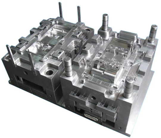
An automotive stamping die is a custom-designed precision tool that cuts, bends, and forms sheet metal into complex three-dimensional shapes. Think of it as a highly engineered mold placed inside a powerful press. When the press closes with tremendous force, the die performs its magic—transforming flat metal blanks into everything from structural body panels to intricate engine components. According to The Phoenix Group, a die can perform four essential functions: locating, clamping, working, and releasing, with value-added operations occurring during the working phase.
What Makes Automotive Stamping Dies Essential to Vehicle Production
Imagine trying to hand-form thousands of identical car doors with perfect dimensional accuracy. Impossible, right? That's precisely why stamping dies are indispensable. These tools enable manufacturers to produce millions of identical parts with tolerances measured in fractions of a millimeter.
The working function of automotive stamping includes cutting, bending, piercing, embossing, forming, drawing, stretching, coining, and extruding. Each operation requires specific die configurations tailored to the exact automotive metal stamping requirements of the part being produced. Without these precision tools, modern mass vehicle production simply wouldn't exist.
A single automotive production line can stamp over 1,000 parts per hour, with each die cycling millions of times throughout its operational life—making precision engineering and durability absolutely critical to manufacturing success.
The Precision Engineering Behind Every Car Panel
What are aftermarket car parts if not components that must match the exact specifications of original equipment? The same stamping principles apply whether you're producing OEM parts or replacement components. Every die consists of carefully designed elements working in harmony:
- Upper and lower shoes – The foundation where all components attach, typically made from cast iron or steel
- Guide pins and bushings – Critical components maintaining precise alignment between die halves
- Punches and die steels – The male and female features that actually shape the material
- Strippers and springs – Systems that release the formed part after each press cycle
Throughout this article, you'll discover the complete journey from raw steel to finished automotive parts. We'll explore different die types, material selection criteria, the engineering design process, validation procedures, maintenance strategies, and cost considerations. Whether you're an engineer, procurement specialist, or manufacturing decision-maker, understanding these precision tools will give you valuable insights into automotive stamping operations and help you make more informed decisions about your production needs.
Types of Stamping Dies Used in Automotive Manufacturing
So you understand what automotive stamping dies do—but did you know there are several distinct types, each engineered for specific production challenges? Choosing the right stamping die isn't just a technical decision. It directly impacts your production speed, part quality, and manufacturing costs. Let's explore the major die categories that power today's auto metal stamping operations.
Progressive Dies for High-Volume Body Components
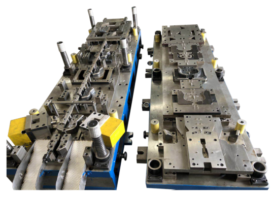
When automotive manufacturers need to produce millions of identical parts quickly, progressive dies are typically the first choice. These metal stamping dies work like a carefully choreographed assembly line contained within a single tool. A continuous metal strip feeds through multiple stations, with each station performing a specific operation—cutting, piercing, bending, or forming—until the finished part emerges at the final stage.
What makes progressive dies so valuable for automotive applications? Consider these advantages:
- Exceptional speed – Parts remain connected to the strip throughout processing, enabling high-speed continuous production
- Reduced labor costs – Minimal handling between operations means fewer workers and lower per-unit expenses
- Consistent quality – Tight integration of operations minimizes variation between parts
- Lower per-part costs – Once tooling investment is made, unit costs drop significantly at high volumes
You'll find progressive dies producing brackets, clips, connectors, transmission components, and electrical terminals throughout the automotive industry. They excel with small to medium-sized parts where production volumes justify the initial tooling investment. However, be aware that design modifications after tooling is complete can be costly and time-consuming.
Transfer Dies for Large Structural Parts
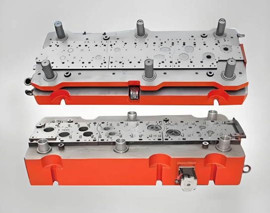
What happens when you need to stamp larger, more complex automotive components that progressive dies simply can't handle? That's where transfer die stamping shines. Unlike progressive systems, transfer dies separate the blank from the metal strip early in the process. Mechanical systems then move individual parts from station to station, with each station performing a specialized operation.
This approach offers distinct advantages for automotive applications:
- Deeper draws – Transfer dies accommodate parts requiring significant three-dimensional forming
- Complex geometries – Individual part handling allows for more intricate shaping operations
- Larger part capability – Ideal for body panels, structural components, and reinforcement plates
- Flexibility in orientation – Parts can be repositioned between stations for multi-directional forming
Major body panels, door frames, structural brackets, and heavy-duty enclosures commonly emerge from transfer die operations. The trade-off? Slightly slower cycle times and higher operational costs compared to progressive stamping. Still, for producing large automotive stamping parts with complex shapes, transfer dies often represent the only practical solution.
Compound Dies for Precision Single-Stroke Operations
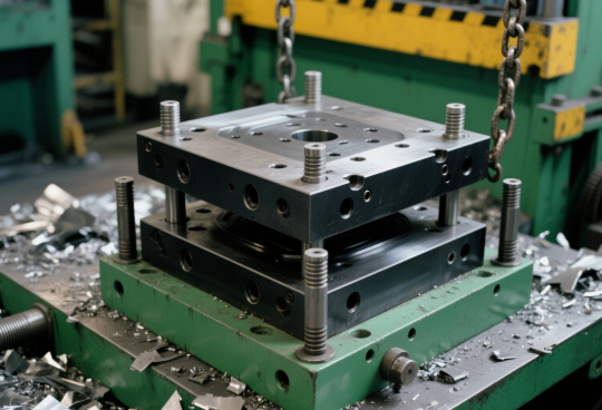
Imagine completing multiple operations—cutting, punching, and blanking—in one powerful press stroke. That's exactly what compound dies deliver. These automotive stamping dies perform overlapping operations simultaneously, making them exceptionally efficient for specific applications.
Compound dies particularly excel when you need:
- High-precision flat parts with tight tolerances
- Multiple features created in perfect alignment
- Reduced cycle time for moderately complex components
- Efficient material usage with minimal scrap
In automotive manufacturing, you'll encounter compound dies producing gaskets, washers, precision shims, and electronic component housings. The simultaneous operations ensure perfect feature alignment—critical for parts where dimensional accuracy cannot be compromised. However, compound dies work best for relatively simple geometries and aren't suited for parts requiring significant bending or deep drawing.
Tandem Dies for Sequential Heavy-Gauge Processing
Some automotive components demand individual attention at each forming stage. Tandem die setups position multiple single-operation dies in sequence, with parts transferred between separate presses. While this approach requires more floor space and handling, it offers unique advantages for heavy-gauge automotive applications.
Tandem configurations work particularly well for:
- Thick-gauge structural components requiring substantial forming force
- Parts needing specialized operations that can't share a single die
- Applications where each forming stage requires different press tonnage
- Production scenarios requiring flexibility to adjust individual operations
Frame components, suspension parts, and heavy structural reinforcements often benefit from tandem die arrangements. Each die stamping machine in the sequence can be optimized for its specific operation, providing maximum control over part quality.
Comparing Die Types for Automotive Applications
Selecting the right die type requires balancing multiple factors. This comparison table summarizes key considerations for each category:
| Die Type | Best Applications | Production Volume Range | Part Complexity Level | Typical Automotive Components |
|---|---|---|---|---|
| Progressive Die | Small to medium parts with multiple features | High volume (100,000+ annually) | Simple to moderate | Brackets, clips, connectors, terminals, transmission components |
| Transfer Die | Large parts with deep draws and complex shapes | Medium to high volume | Moderate to high | Body panels, door frames, structural brackets, reinforcement plates |
| Compound Die | Flat precision parts with multiple simultaneous operations | Medium to high volume | Simple to moderate | Gaskets, washers, shims, electronic housings |
| Tandem Die | Heavy-gauge parts requiring sequential forming | Low to medium volume | Moderate to high | Frame components, suspension parts, structural reinforcements |
When evaluating which die type fits your automotive stamping needs, consider your production volume first. High-volume runs almost always favor progressive dies due to their speed and low per-part costs. For larger structural components or parts requiring deep draws, transfer dies provide the necessary flexibility. Compound dies offer efficiency when precision flat parts need multiple features in perfect alignment. And tandem arrangements give you maximum control for heavy-gauge applications where each operation benefits from individual optimization.
Understanding these die categories sets the foundation for deeper decisions about materials, engineering, and production planning. But what materials actually go into building these precision tools? The answer significantly impacts die performance, longevity, and the quality of your finished automotive stamping parts.
Die Materials and Selection Criteria for Automotive Applications
You've seen how different die types serve various automotive manufacturing needs. But here's a question that often gets overlooked: what are these precision tools actually made from? The materials inside your steel stamping dies directly determine how long they'll last, how consistent your parts will be, and ultimately, how much your steel stampings will cost over time. Let's explore the critical material choices that separate mediocre dies from exceptional ones.
Choosing die materials isn't guesswork. According to manufacturing experts at Alsette, picking the wrong material leads to failed parts and broken, expensive tools. The right selection requires balancing extreme hardness, wear resistance, toughness to avoid cracking, good machinability for shaping the die, and overall cost-effectiveness for production volumes.
Tool Steel Selection for Body Panel Dies
Tool steels form the backbone of most sheet metal stamping dies. These specialized carbon alloy steels contain between 0.5% and 1.5% carbon, along with carbides formed by four primary alloying elements: tungsten, chromium, vanadium, and molybdenum. Each formulation offers distinct advantages depending on your automotive application.
D2 Tool Steel – The Wear Resistance Champion
When your dies face high-volume production runs forming automotive sheet steel, D2 tool steel often emerges as the preferred choice. This high-carbon, high-chromium material is renowned for exceptional wear resistance. The significant chromium content forms hard carbide particles that resist abrasion through millions of press cycles.
- Hardness: Achieves 62-64 HRC after hardening and tempering
- Best applications: Long-run blanking, punching, and forming dies requiring close tolerances
- Heat treatment: Hardened at 1800°F to 1875°F, tempered between 900°F and 960°F
- Ideal for: High-volume body component production where wear resistance trumps impact toughness
A2 Tool Steel – Balancing Toughness and Wear
Need a material that handles both forming operations and maintains dimensional stability? A2 tool steel offers an excellent balance. With 5% chromium content, this air-hardening steel provides high hardness after heat treatment while maintaining better toughness than D2.
- Hardness: Reaches 63-65 HRC as-hardened
- Best applications: Blanking and forming punches, die trimming, injection molding dies
- Heat treatment: Air-quenched from hardening temperature, tempered at 350°F to 400°F
- Ideal for: Applications requiring excellent dimensional stability and moderate wear resistance
S7 Tool Steel – Impact Resistance Specialist
Some automotive die tooling faces significant mechanical shock during operation. S7 shock-resistant tool steel was engineered precisely for these demanding conditions. This air-hardening material delivers high toughness and impact resistance that other tool steels simply can't match.
- Hardness: Achieves 60-62 HRC when hardened
- Best applications: Chisels, punches, rivet sets, and dies experiencing significant impact loading
- Heat treatment: Hardened at 1725°F to 1850°F, tempered at 400°F for cold-working or up to 1000°F for hot-working
- Ideal for: Forming operations with heavy impact or dies prone to cracking from shock loads
Carbide Applications in High-Wear Stamping Operations
What happens when even the best tool steels wear too quickly? For extreme durability requirements, cemented carbide inserts enter the picture. Carbide is significantly harder than any tool steel, offering superior wear resistance in the most demanding stamping environments.
According to Alicona's precision die manufacturing guide, carbide dies are often found in high-precision applications where extended die life justifies the higher cost. However, carbide comes with trade-offs—it's more expensive and more brittle than tool steel.
- Primary advantage: Exceptional hardness and wear resistance far exceeding tool steels
- Common applications: Critical cutting edges, high-wear punch tips, precision forming surfaces
- Typical implementation: Carbide inserts brazed into tool steel die bodies rather than solid carbide construction
- Best suited for: Ultra-high-volume production where extended die life offsets higher material costs
Many manufacturers use a hybrid approach—constructing the main die body from gray or ductile cast iron for stability and cost efficiency, then incorporating tool steel or carbide inserts at high-wear locations. This strategy optimizes both performance and economics.
Connecting Material Selection to Automotive Requirements
Your material choice must align with specific automotive industry demands. Consider these critical connections:
Crash Performance Standards: Structural components requiring precise dimensional accuracy demand die materials that maintain their shape through extended production runs. D2 and carbide inserts excel here, ensuring consistent part geometry that meets safety specifications.
Weight Reduction Goals: As automakers shift toward lighter-gauge high-strength steels and aluminum, die materials must handle increased forming forces without premature wear. Higher hardness tool steels become essential when stamping advanced high-strength steel (AHSS) grades.
High-Volume Production Demands: When your dies need to produce millions of parts, material selection directly impacts total cost of ownership. A die that lasts twice as long before requiring refurbishment or replacement can dramatically reduce your per-part costs—even if initial tooling investment is higher.
Surface coatings add another dimension to material performance. Coatings such as Titanium Nitride (TiN), Chromium Nitride (CrN), or Diamond-Like Carbon (DLC) reduce friction, minimize adhesive wear, and extend tool life. These treatments prove especially valuable when plating stamped components requires pristine surface finishes from the stamping operation.
The relationship between material choice and die longevity directly affects your production economics. Understanding these connections helps you evaluate die suppliers more effectively—and positions you to ask the right questions about engineering tolerances and design processes that transform these materials into precision manufacturing tools.
The Die Design and Engineering Process Explained
You now understand die materials and their critical role in automotive stamping. But how does a concept become a production-ready tool capable of forming millions of precise parts? The die design engineering process bridges the gap between automotive component requirements and physical tooling. This journey involves sophisticated digital workflows, precise tolerance calculations, and virtual validation—all before cutting a single piece of steel. Let's walk through the automotive metal stamping process from initial concept to final engineering release.
According to precision manufacturing specialists at U-Need Precision Manufacturing, stamping die design is a systematic process that creates a comprehensive blueprint outlining each part of the die, its exact dimensions, material specifications, and how components interact to transform flat metal into complex three-dimensional parts. This blueprint directly affects four critical outcomes: part quality, production cost, manufacturing speed, and operational reliability.
From CAD Model to Production-Ready Die Design
Modern die stamping begins long before any physical machining. The journey starts with detailed digital models and progresses through multiple engineering stages. Here's how stamping die manufacturers transform concepts into production-ready tooling:
-
Part Print Analysis and Feasibility Assessment
Before any design work begins, engineers conduct thorough part print analysis. This critical gatekeeping process determines whether stamping is the most feasible and cost-effective production method. Engineers evaluate part geometry, material specifications, tolerance requirements, and production volumes. Complex features that might require secondary operations are identified early, allowing for design modifications that simplify manufacturing. -
Strip Layout Development
For progressive and transfer dies, the strip layout represents the soul of the design. Engineers arrange all cutting and forming operations in optimal sequence as the metal strip moves through the die with each press stroke. Key considerations include material utilization (minimizing scrap), operation sequence logic, and press stroke requirements. This iterative process often involves multiple concepts before arriving at the most efficient solution. -
3D Component Modeling and Detailed Design
With the strip layout finalized, attention shifts to designing individual stamping die components. Engineers create extensive 3D models and 2D drawings for all punches, die buttons, stripper plates, guide pins, and other elements. Every dimension, material specification, and surface finish requirement is documented. This stage defines how each component interacts within the complete tool assembly. -
CAE Simulation and Virtual Validation
Modern die design no longer relies on trial and error. Computer-Aided Engineering (CAE) and Finite Element Analysis (FEA) software simulate the entire stamping process digitally. Engineers predict material flow, identify potential thinning or splitting, calculate springback compensation, and optimize process parameters—all before physical construction begins. -
Design Optimization and Engineering Release
Simulation results drive design refinements. Engineers modify die geometry, adjust clearances, and incorporate compensation features based on virtual testing. Once all parameters meet specifications, the design receives final engineering release, generating manufacturing data for CNC programming, wire EDM, and grinding operations.
This structured approach dramatically reduces physical tryout iterations. As one metal stamping automotive expert noted, it's far cheaper and faster to adjust a digital model than to re-machine hardened tool steel.
Engineering Tolerances That Define Part Quality
Why do some stamped parts fit perfectly while others require constant adjustment? The answer lies in engineering tolerances built into die design. These precise specifications govern every aspect of tooling performance.
Clearance Calculations
The gap between punch and die—known as clearance—directly affects edge quality, tool life, and forming accuracy. Too little clearance causes excessive tool wear and requires higher forming forces. Too much clearance produces burrs, rough edges, and dimensional variation. For automotive applications, clearance typically ranges from 5% to 15% of material thickness, depending on the specific operation and material grade.
Material Thickness Considerations
Automotive sheet steel varies in thickness, even within specified tolerances. Die designs must accommodate this variation while still producing acceptable parts. Engineers build tolerance stacks that account for material variation, thermal expansion during production, and progressive tool wear over millions of cycles.
Springback Compensation
Here's where die design becomes genuinely sophisticated. When formed metal is released from the die, stored elastic energy causes it to partially return toward its original shape—a phenomenon called springback. According to ETA's technical guide on springback prevention, this problem is far more pronounced in High-Strength Steel (HSS) and Advanced High-Strength Steel (AHSS) due to their high yield strength.
Modern simulation software predicts springback magnitude and direction across entire part surfaces. Engineers then modify die geometry to create "compensated" tool faces—intentionally forming parts into an incorrect shape so they spring back into the correct, desired geometry. This predictive approach replaces costly physical trial-and-error methods that simply cannot keep pace with today's production demands.
The Stamper Automotive Challenge: Complex Geometry
The relationship between die complexity and part geometry follows a clear pattern. Parts with deep draws, sharp radii, multiple bends, and tight dimensional requirements demand more sophisticated tooling. Each geometric feature influences material flow during forming. Simulation helps engineers understand these interactions before committing to physical construction.
Using platforms like AutoForm or DYNAFORM, engineering teams can:
- Predict material thinning and potential splitting during deep draws
- Optimize blank holder forces for uniform material flow
- Identify wrinkling tendencies and adjust binder surfaces accordingly
- Calculate precise springback compensation for complex geometries
- Validate die designs against automotive quality standards before construction
This virtual validation process enables rapid iteration and refinement. Minor inaccuracies in material modeling or solver calculations can lead to incorrect compensation, but today's advanced simulation tools minimize these risks. The result? Dramatically increased probability of first-time success and significantly shortened physical tryout periods.
The integration of CAD, CAM, and CAE software creates a digital thread connecting initial part concepts to finished, physically-machined tooling. This seamless workflow ensures that engineering intent translates accurately into production reality—setting the stage for the die tryout and validation procedures that confirm everything works as designed.
Die Tryout and Validation Before Production
Your die design is complete, materials are selected, and the physical tool has been constructed. But here's a critical question many overlook: how do you know it will actually work? The die tryout and validation phase bridges the gap between engineering theory and production reality. This intensive process transforms a newly manufactured tool into a proven, production-ready asset—yet it's one of the least discussed topics in stamping manufacturing literature.
According to stamping experts at Shaoyi, die tryout is not a one-time event but an intensive fine-tuning phase. It's a systematic process of validation that ensures the die can transform flat sheet metal into complex, three-dimensional parts that adhere perfectly to design specifications.
Die Tryout Procedures That Ensure Production Success
Think of die tryout as the proving ground where precision engineering meets real-world conditions. The process follows a structured sequence that systematically identifies and resolves issues before they impact production. Here's how industrial stamping professionals validate new tooling:
-
Initial Press Setup and First Stamping
The newly assembled die is carefully installed into a tryout press. Technicians load the specified sheet metal and run the press to produce the first sample parts. During this stage, press settings like tonnage and cushion pressure are adjusted to establish baseline performance parameters. -
First-Piece Inspection and Defect Identification
The initial parts undergo rigorous examination immediately after forming. Visual checks identify obvious defects like cracks, wrinkles, or surface scratches. More importantly, advanced metrology tools—Coordinate Measuring Machines (CMMs) or 3D laser scanners—compare the part's geometry against the original CAD model with micron-level precision. -
Die Spotting and Debugging
When discrepancies surface, the debugging phase begins. A traditional technique called "die spotting" involves applying a blue paste to the sheet metal before pressing. The paste transfer pattern reveals high and low spots where die surfaces aren't making uniform contact. Technicians then use precision grinding and polishing to correct these imperfections. -
Iterative Adjustments and Re-Stamping
Based on inspection and spotting results, skilled toolmakers make precise modifications. This could involve grinding forming surfaces, welding material to add stock, or adding shims to adjust clearances. After each adjustment, the die is re-stamped and new parts are inspected—beginning the correction loop anew. -
Production Rate Testing and Final Validation
Once dimensional requirements are satisfied, testing shifts to production speed. The die must perform consistently at intended cycle rates without degradation in part quality. Only after sustained successful runs does the tool receive approval for full production release.
This iterative approach may seem time-consuming, but it's essential. Research highlighted by Academia.edu shows that tolerance adjustments occur in over 50% of dimensions during vehicle launches, reflecting the inherent variability in metal parts stamping processes.
Common Issues Discovered During Tryout
What problems typically emerge when a new die first meets the press? Understanding these challenges helps you evaluate die quality and supplier capability:
- Splits and Cracks – Material stretched beyond its forming limits, often requiring adjustments to draw beads or blank holder pressure
- Wrinkling – Insufficient restraint allowing material to buckle, typically corrected by modifying binder surfaces or increasing blank holder force
- Springback Deviation – Parts returning toward their original shape after forming, necessitating die compensation adjustments
- Tool Deflection Effects – Die and press components bending under forming loads, causing non-uniform pressure distribution
- Surface Defects – Scratches, scuffs, or deformation marks unacceptable for visible automotive marking on Class A surfaces
- Dimensional Drift – Parts outside tolerance due to material variation or thermal effects during extended runs
Validation Metrics for Automotive Quality Standards
How do you know when a die is truly production-ready? Automotive OEMs and Tier 1 suppliers rely on specific validation checkpoints and acceptance criteria that must be satisfied before part approval:
- Dimensional Conformance – All critical dimensions within specified tolerances, verified through CMM measurement against GD&T specifications
- Surface Quality Standards – No visible defects on Class A surfaces; automotive part marking requirements satisfied for traceability
- Material Properties Verification – Hardness, thickness, and mechanical properties confirmed within specification
- Process Capability Metrics – Cpk values demonstrating statistical process control capability (typically Cpk ≥ 1.33 for automotive applications)
- Production Rate Validation – Sustained operation at target cycle times without quality degradation
- Initial Sample Inspection Report (ISIR) – Comprehensive documentation package providing detailed measurement data for customer approval
A methodology validated during recent vehicle program launches showed that multi-run evaluation approaches predicted over 90% of actual variation levels observed later in production—dramatically improving tolerance adjustment accuracy.
First-Pass Approval Rates: The Ultimate Quality Indicator
Want to quickly assess a die supplier's engineering precision? Ask about their first-pass approval rate. This metric reveals what percentage of dies achieve customer approval without requiring significant rework after initial tryout. Industry leaders like Shaoyi achieve 93% first-pass approval rates—a testament to their advanced CAE simulation capabilities that predict and prevent defects before physical construction begins.
Higher first-pass rates translate directly to faster time-to-production and lower total tooling costs. When simulation accurately predicts material flow, springback, and potential failure modes, physical correction loops decrease dramatically. Modern virtual tryout capabilities can reduce physical iteration time by more than half compared to traditional trial-and-error approaches.
The validation phase ultimately determines whether your investment in precision engineering pays off in consistent, high-quality production. But even the best-validated die requires ongoing attention. Understanding maintenance strategies and troubleshooting common failures ensures your tooling delivers optimal performance throughout its operational life.
Die Maintenance and Troubleshooting Common Failures
Your die passed validation and entered production. But here's a reality many manufacturers underestimate: the moment stamping begins, wear begins. Every press cycle subjects your tooling to tremendous mechanical stress, friction, and thermal loading. Without proper maintenance, even the finest stamping dies manufacturer can't prevent gradual degradation that eventually compromises part quality and production efficiency. Let's explore how strategic maintenance extends die life and keeps your stamping metal parts consistently within specification.
According to maintenance specialists at Keneng Hardware, regular maintenance helps identify and address potential issues before they escalate into major problems. By conducting routine inspections and addressing wear promptly, manufacturers can prevent unexpected die failures that lead to costly downtime and production delays.
Preventive Maintenance Schedules for Maximum Die Life
Imagine treating die maintenance like vehicle maintenance—would you skip oil changes until your engine fails? The same logic applies to your metal stamping tooling. Proactive care dramatically outperforms reactive repairs in both cost and production continuity.
Effective preventive maintenance programs include multiple activities at varying intervals. Here's a comprehensive comparison of key maintenance activities:
| Maintenance Activity | Frequency | Impact on Die Performance | Consequences of Neglect |
|---|---|---|---|
| Visual inspection of cutting edges | Every production run | Early detection of wear, chipping, or damage | Burrs on parts, dimensional drift, sudden failure |
| Cleaning and debris removal | Daily or per shift | Prevents contamination, maintains surface quality | Surface defects, accelerated wear, galling |
| Lubrication system check | Daily | Reduces friction, prevents adhesive wear | Galling, scoring, premature tool failure |
| Guide pin and bushing inspection | Weekly | Ensures proper alignment between die halves | Misalignment, uneven wear, part dimensional issues |
| Cutting edge sharpening | Every 50,000-150,000 strokes (varies by material) | Restores clean cutting action, reduces forming forces | Increased burr height, edge rollover, part rejection |
| Spring replacement and pressure checks | Monthly or per scheduled interval | Maintains proper stripping and blank holding forces | Incomplete stripping, wrinkling, inconsistent forming |
| Dimensional verification | Quarterly or after significant production runs | Confirms critical dimensions remain within tolerance | Out-of-spec parts, customer rejections, costly rework |
| Complete die teardown and inspection | Annually or per stroke count threshold | Identifies hidden wear, validates all components | Catastrophic failure, extended downtime, safety hazards |
Sharpening intervals deserve special attention. According to industry maintenance guidelines, maintaining sharp cutting edges ensures clean and precise part formation. Use sharpening tools such as abrasive stones or grinding wheels to restore sharpness and remove burrs or nicks. For heavily worn or damaged dies, consider refurbishment techniques such as welding, machining, or regrinding to restore original dimensions.
Common Die Failure Modes and Their Solutions
When problems emerge, quick diagnosis prevents minor issues from becoming major production disruptions. Understanding common failure patterns helps you respond effectively:
Galling and Adhesive Wear
Ever noticed material buildup on die surfaces that transfers onto your parts? That's galling—one of the most frustrating problems in variety die and stamping operations. It occurs when intense pressure and friction cause sheet metal to weld momentarily to the die surface, then tear away.
- Symptoms: Rough surface finish on parts, visible material buildup on die faces, scratching patterns
- Root causes: Inadequate lubrication, excessive blank holder force, improper die clearances, incompatible material combinations
- Solutions: Improve lubrication coverage and viscosity, apply anti-galling coatings (TiN or DLC), polish affected surfaces, adjust blank holder pressure
Abrasive Wear
This gradual erosion occurs as sheet metal slides across die surfaces under pressure. Unlike galling, abrasive wear creates grooved patterns aligned with material flow direction.
- Symptoms: Progressive dimensional drift, visible wear tracks, increased burr formation
- Root causes: Hard particles in sheet material, scale or oxide contamination, insufficient surface hardness
- Solutions: Upgrade to harder die materials or carbide inserts, apply hard coatings, improve incoming material cleanliness, increase sharpening frequency
Cracking and Chipping
Sudden fractures in stamping tooling often trace back to impact loading, improper heat treatment, or fatigue accumulation over millions of cycles.
- Symptoms: Visible cracks or missing material at cutting edges, sudden changes in part quality
- Root causes: Excessive forming forces, shock loading, material fatigue, improper clearances, heat treatment defects
- Solutions: Reduce forming speeds, verify proper clearances, use shock-resistant tool steels (like S7), implement stress-relief heat treatment, repair via precision welding and remachining
Misalignment Issues
When upper and lower die halves don't meet precisely, the results show immediately in your parts. Misalignment creates uneven wear patterns, dimensional inconsistency, and accelerated component degradation.
- Symptoms: Uneven burr distribution, asymmetric wear on guide components, dimensional variation across part features
- Root causes: Worn guide pins and bushings, loose fasteners, press ram deflection, improper die setting
- Solutions: Replace worn guide components, verify and torque all fasteners, check press alignment, recalibrate die setting procedures
Recognizing When Dies Need Refurbishment or Replacement
Here's the million-dollar question: when do you repair versus replace? Making this decision incorrectly either wastes money on excessive repairs or prematurely discards valuable tooling. Consider these decision criteria:
Indicators Favoring Refurbishment:
- Wear confined to replaceable inserts or easily accessible surfaces
- Part quality still achievable after documented adjustment range
- Die structure and critical dimensions remain sound
- Refurbishment cost less than 40-50% of replacement cost
- Production requirements continue for the foreseeable future
Indicators Favoring Replacement:
- Core structural damage or widespread fatigue cracking
- Cumulative rework has consumed available material allowance
- Part design changes require significant die modifications
- Repeated failures despite multiple repair attempts
- Technology advances offer significant performance improvements
According to forming die specialists at Jeelix, a robust refurbishment decision must weigh three factors: operational efficiency gains from a new die, residual production value from the existing die, and cost of production disruption during replacement. These considerations form the foundation for data-driven tooling lifecycle management.
Proper maintenance transforms dies from depreciating assets into long-term production partners. When your stamping tooling receives consistent attention, it rewards you with dimensional stability, surface quality, and reliable operation throughout extended production campaigns. But maintenance is just one piece of the puzzle—understanding how different automotive applications demand varying die specifications helps you optimize tooling for your specific component requirements.
Automotive Applications and Component-Specific Die Requirements
You've learned how dies are designed, validated, and maintained. But here's what truly separates exceptional tooling from adequate tooling: understanding that different automotive components demand fundamentally different die specifications. A die that produces flawless body panels might fail completely when forming structural safety components. Why? Because each vehicle system presents unique challenges in tolerances, material grades, production volumes, and quality requirements. Let's explore how automotive metal stampings vary across critical vehicle applications.
According to manufacturing specialists at Neway Precision, stamping and deep drawing are critical processes for producing large, durable auto parts with high precision. However, tolerance and precision requirements vary dramatically depending on whether you're forming engine brackets or Class A exterior panels.
Die Requirements for Structural Safety Components
When vehicle occupants depend on components to protect them during collisions, there's zero tolerance for compromise. Structural safety parts—including B-pillars, door intrusion beams, roof reinforcements, and crash rails—demand the most rigorous die specifications in the entire vehicle.
What makes these automotive metal stamping parts so demanding? Consider the unique requirements:
- Advanced High-Strength Steel (AHSS) Compatibility – Modern safety components increasingly use materials like dual-phase steel, martensitic steel, and press-hardened boron steel with tensile strengths exceeding 1,000 MPa. Dies must withstand significantly higher forming forces without premature wear or deflection.
- Tight Dimensional Tolerances – Crash performance depends on precise geometry. Typical tolerances of ±0.3 mm to ±0.5 mm ensure components fit correctly and absorb energy as designed during impact events.
- Consistent Material Thickness – Wall thickness variations directly affect energy absorption capacity. Deep-drawn safety components require dies engineered for uniform thickness distribution throughout the forming process.
- Weld Flange Precision – Most structural components join to other body elements through resistance spot welding. Die designs must maintain flange flatness and positioning to ensure reliable weld quality.
- Springback Compensation – AHSS materials exhibit pronounced springback due to high yield strength. As noted in ADHMT's tolerance guide, this phenomenon is far more pronounced in High-Strength Steel, requiring sophisticated die compensation strategies.
For structural components, auto stamping operations typically employ transfer dies or tandem die setups. These configurations handle the deeper draws and complex geometries characteristic of safety-critical parts while providing the flexibility to form high-strength materials without splitting or excessive thinning.
Precision Demands in Body Panel Stamping
Imagine walking through a showroom and immediately noticing uneven gaps between body panels or subtle surface waviness catching the light. That's the nightmare scenario body panel stamping must prevent. Class A exterior surfaces—hoods, doors, fenders, and quarter panels—face aesthetic requirements just as demanding as structural components face safety requirements.
- Surface Quality Standards – Any visible defect disqualifies the part. Dies must produce mirror-smooth surfaces free from scratches, tool marks, or orange peel texture. This demands polished die surfaces, optimal lubrication, and precise blank holder control.
- Gap and Flush Tolerances – Consumer perception of vehicle quality often starts with panel fit. Tolerances of ±0.5 mm for gap width and ±0.3 mm for flushness between adjacent panels require exceptional die precision.
- Material Flow Control – Large exterior panels are susceptible to wrinkling, splitting, and uneven stretching. Draw beads and blank holder designs must control material flow precisely to prevent surface defects that would be invisible on hidden components but unacceptable on visible surfaces.
- Aluminum Panel Considerations – Weight reduction initiatives have increased aluminum body panel usage. Aluminum requires different die clearances, lubrication strategies, and forming speeds compared to steel, demanding specialized tooling approaches.
- High Production Volumes – Body panels represent some of the highest-volume stamped components. Dies must maintain surface quality through millions of cycles, often requiring carbide inserts at high-wear locations.
Engine and Powertrain Component Requirements
Moving under the hood, metal stampings for automotive components face entirely different challenges. Engine covers, transmission housings, oil pans, and heat shields must withstand extreme temperatures, vibration, and fluid exposure throughout vehicle life.
- Thermal Resistance – Components near engines experience continuous thermal cycling. Progressive stamped automotive parts for these applications often use stainless steel or aluminum alloys selected for thermal stability.
- Sealing Surface Precision – Oil pans, valve covers, and similar components require flatness tolerances within 0.1 mm to 0.2 mm at sealing interfaces. Any distortion leads to fluid leaks and warranty claims.
- Deep Draw Capability – Many powertrain enclosures require significant depth. According to Neway Precision, deep drawing is ideal for manufacturing components with significant depth, such as automotive body panels, fuel tanks, and specific engine parts.
- Vibration Resistance Features – Dies often incorporate features that create mounting points, reinforcement ribs, or damping surfaces designed to minimize noise and vibration transmission.
Chassis and Suspension Components
The components connecting your vehicle to the road demand exceptional durability. Control arms, crossmembers, subframes, and suspension brackets experience continuous dynamic loading throughout millions of road surface impacts.
- Heavy-Gauge Material Processing – Chassis components frequently use thicker gauges (2.0 mm to 4.0 mm or more) for strength requirements. Dies must handle increased forming forces and potential springback from heavier materials.
- Fatigue-Critical Geometry – Sharp corners and abrupt section changes create stress concentrations leading to fatigue failure. Die designs incorporate generous radii and smooth transitions to enhance component longevity.
- Mounting Point Precision – Suspension geometry depends on precise bushing and bolt hole locations. Positional tolerances of ±0.25 mm ensure proper wheel alignment and handling characteristics.
- Corrosion Resistance Considerations – Underbody components face salt, water, and debris exposure. Dies must accommodate materials or coatings selected for corrosion resistance without compromising formability.
Seat Frame and Interior Structural Applications
Seat structures occupy a unique position—they're both safety-critical (securing occupants during crashes) and subject to aesthetic requirements (visible in some designs). This dual role creates distinct die requirements:
- Mixed Material Strategies – Modern seat frames often combine high-strength steel for structural rails with lighter materials for non-critical brackets, requiring dies optimized for specific material grades.
- Recliner Mechanism Precision – The interface between seat structures and recliner mechanisms demands tight tolerances for smooth adjustment operation throughout vehicle life.
- Weight Optimization – Every gram matters in seat design. Dies increasingly form complex geometries that maximize strength-to-weight ratios through strategic material placement.
- Volume Flexibility – Seat configurations vary across trim levels and markets. Die designs must balance production efficiency with the flexibility to serve multiple variants.
OEM Production Versus Aftermarket Manufacturing
Does it matter whether automotive metal stampings serve original equipment production or aftermarket replacement? Absolutely. While the fundamental forming processes remain similar, several factors differentiate these applications:
- Volume Considerations – OEM production typically involves higher volumes justifying progressive or transfer die investments. Aftermarket volumes may favor simpler die configurations with lower upfront costs.
- Tolerance Expectations – OEM specifications often demand tighter tolerances than aftermarket applications, where fit with existing vehicles matters more than matching original manufacturing precision.
- Material Traceability – OEM production requires complete material certification and traceability. Aftermarket manufacturers may have more flexibility in material sourcing while still meeting functional requirements.
- Certification Requirements – Safety-critical aftermarket components increasingly require certification demonstrating equivalence to original equipment—a trend driving higher quality standards across the replacement parts industry.
Understanding these application-specific requirements helps you match die capabilities to component demands. But how do you balance these technical requirements against investment costs? The economics of die selection deserve careful analysis before committing to any tooling program.
Cost Factors and ROI Analysis for Die Investment
You understand die types, materials, and application requirements. But here's the question that ultimately drives every tooling decision: what will it actually cost, and will the investment pay off? Automobile parts manufacturing economics extend far beyond the initial purchase price. Smart decision-makers evaluate total cost of ownership across the entire production lifecycle—and that calculation often reveals surprising conclusions about which die type delivers the best value for your specific situation.
According to stamping cost specialists at Be-Cu, stamping cost is a systematic cost. If the stamping form analysis is separated from the whole and only focuses on a single cost, the conclusions drawn will not be objective. Understanding the complete financial picture requires examining multiple interconnected factors.
Calculating True Cost Per Part Across Production Volumes
Imagine you're choosing between two die options: one costs significantly more upfront but runs faster with lower maintenance. The other costs less initially but requires more frequent attention. Which is actually cheaper? The answer depends entirely on your production volume—and calculating true cost per part reveals the crossover points where each option makes sense.
The fundamental cost-per-part calculation considers these primary elements:
- Initial die investment – The upfront tooling cost amortized across total expected production volume
- Material costs – Sheet metal consumption including scrap rates, which vary by die type and design efficiency
- Labor costs – Operator time per part, dramatically different between manual and automated stamping production
- Machine time – Press operating costs calculated by dividing power and overhead by hourly production rates
- Maintenance allocation – Sharpening, repair, and eventual refurbishment costs distributed across part quantities
- Quality costs – Inspection requirements, rejection rates, and rework expenses
Here's where volume changes everything. A progressive die producing 200 parts per minute spreads its higher initial cost across vastly more units than a manual single-operation die running 20 parts per minute. At low volumes, that expensive progressive die delivers punishing per-part costs. At high volumes, it becomes remarkably economical.
Investment Thresholds for Progressive Versus Transfer Dies
When does each die type make financial sense? Car parts manufacturing decisions often hinge on identifying these critical volume thresholds. According to industry cost analysis, the output determines whether to choose manual stamping production or automatic stamping production. The greater the life cycle output, the more obvious the economy of automated production.
Consider these general threshold guidelines:
- Manual single-die operations – Economically viable when life cycle consumption stays below 200,000 strokes, especially under 100,000. The savings on mold and automation investment typically exceed increased labor costs at these volumes.
- Automatic tandem production – Becomes attractive for life cycle volumes exceeding 200,000 units, particularly for large or medium-sized products like automobile cover parts, body chassis components, and appliance shells.
- Transfer die production – Optimal for volumes over 200,000 with medium or small-sized products requiring deep drawing, such as A, B, C-pillars, seat frame components, and motor housings.
- Progressive die production – Most economical for volumes exceeding 200,000 with small to medium-sized parts like connectors, motor core laminations, and terminal products.
The structural characteristics of your stamping car parts determine which automated form you should choose. Deep draws favor transfer dies. Small intricate parts with multiple features favor progressive dies. Heavy-gauge structural components may require tandem setups regardless of volume.
Comparing Total Cost of Ownership Across Die Types
Looking only at initial die cost misses the bigger picture. Car component manufacturers who evaluate total cost of ownership make better investment decisions. This comprehensive comparison illustrates key economic factors:
| Cost Factor | Progressive Die | Transfer Die | Compound Die | Manual/Tandem |
|---|---|---|---|---|
| Initial Investment | Highest | High | Moderate | Lowest |
| Per-Part Labor Cost | Lowest | Low | Moderate | Highest |
| Production Speed | Fastest | Fast | Moderate | Slowest |
| Material Utilization | Good (strip-fed) | Moderate | Good | Variable |
| Maintenance Frequency | Moderate | Moderate | Lower | Lower |
| Setup/Changeover Time | Longer | Moderate | Shorter | Shortest |
| Part Size Capability | Small to medium | Medium to large | Small to medium | Any size |
| Break-Even Volume | Highest threshold | High threshold | Moderate threshold | Lowest threshold |
Framework for ROI Analysis
How do automotive stamping companies evaluate die investments systematically? A structured ROI framework considers five interconnected cost categories across the entire project lifecycle:
- Total Project Life Cycle Volume – Estimate total units required over the product's lifetime, including potential model year extensions and aftermarket demand
- Single Stamped Product Cost – Calculate material, labor, machine time, and overhead per unit for each die type option
- Mold Investment in Project Cycle – Include initial die cost, engineering, tryout expenses, and anticipated mid-life refurbishment
- Inspection and Quality Tooling – Account for checking fixtures, gauges, and measurement equipment required for production validation
- Quality Risk Costs – Estimate potential warranty exposure, sorting costs, and customer disruption if quality issues emerge
When comparing options, calculate the total expenditure for each die type across your projected volume. The option with the lowest total cost—not the lowest initial investment—typically represents the best value. Remember that higher-quality dies from reputable suppliers often deliver lower total costs despite higher purchase prices, thanks to reduced maintenance, fewer production disruptions, and consistent part quality.
Die investment decisions shape your production economics for years or even decades. Understanding these cost dynamics positions you to ask the right questions when evaluating potential stamping partners—questions about engineering capabilities, quality systems, and the expertise that transforms tooling investments into manufacturing success.
Selecting the Right Stamping Die Partner for Your Production Needs
You've analyzed die types, understood material requirements, and calculated your investment thresholds. Now comes the decision that will ultimately determine whether your automotive stamping die program succeeds or struggles: choosing the right manufacturing partner. This choice extends far beyond comparing quotes. The right partner delivers tooling that meets specifications on the first attempt, supports your production timeline, and provides responsive service when challenges arise. The wrong partner costs you time, money, and potentially your customer relationships.
So how do you separate exceptional automotive parts manufacturers from adequate ones? The answer lies in evaluating specific capabilities, certifications, and track records that predict future performance. Let's explore the criteria that matter most when selecting your stamping die partner.
Certification Standards That Indicate Manufacturing Excellence
When you're evaluating who offers the best quality in automotive aftermarket or OEM production, certifications provide objective evidence of manufacturing capability. But not all certifications carry equal weight in the automotive stamping world.
IATF 16949: The Automotive Quality Benchmark
If a stamping die supplier lacks IATF 16949 certification, that's an immediate red flag for automotive applications. This internationally recognized standard specifically addresses quality management systems for automotive production and relevant service parts. It goes beyond basic ISO 9001 requirements to include automotive-specific processes like Advanced Product Quality Planning (APQP), Production Part Approval Process (PPAP), and Failure Mode and Effects Analysis (FMEA).
What does IATF 16949 certification actually tell you about a supplier?
- Documented quality systems – Every process from design through delivery follows controlled procedures
- Continuous improvement culture – The organization actively measures and enhances performance
- Customer-specific requirements – Systems accommodate unique OEM specifications and expectations
- Supply chain management – Subcontractors and material suppliers meet defined standards
- Traceability capabilities – Complete documentation links finished tooling to raw materials and processes
Partners like Shaoyi maintain IATF 16949 certification specifically because automotive customers require this level of quality assurance. When evaluating best aftermarket auto parts brands or OEM suppliers, this certification should be your baseline requirement—not a differentiator.
Additional Certifications Worth Noting
Beyond IATF 16949, consider these supplementary credentials:
- ISO 14001 – Environmental management systems demonstrating responsible manufacturing practices
- ISO 45001 – Occupational health and safety management, indicating workforce investment
- Customer-specific certifications – Some OEMs require additional qualifications for approved supplier status
Engineering Capabilities That Reduce Time to Production
Certifications confirm quality systems exist. But engineering capabilities determine whether your custom automotive metal stamping project will proceed smoothly or encounter costly delays. Here's what separates leading auto parts manufacturers in usa and globally from basic tool shops.
CAE Simulation for Defect Prevention
Remember our earlier discussion about die tryout and validation? The best partners minimize physical iteration by catching problems digitally. Advanced CAE (Computer-Aided Engineering) simulation predicts material flow, identifies potential splitting or wrinkling, calculates springback compensation, and optimizes process parameters before any steel is cut.
What should you look for in simulation capabilities?
- Material database depth – Accurate simulation requires precise material property data for the specific grades you'll be forming
- Springback prediction accuracy – Especially critical for high-strength steel components where compensation is essential
- Integration with design workflow – Simulation results should drive design modifications seamlessly
- Validation track record – Ask how simulation predictions correlate with actual tryout results
Partners investing in advanced simulation deliver defect-free results more consistently. This capability directly impacts your timeline and budget by reducing physical tryout iterations.
Rapid Prototyping Speed
In today's compressed development cycles, waiting months for prototype tooling isn't acceptable. Leading aftermarket industries suppliers and OEM partners offer rapid prototyping capabilities that accelerate your validation timeline.
How fast is fast enough? Top-tier suppliers can deliver prototype components in as little as 5 days for urgent requirements. This speed enables earlier design validation, faster iteration on potential issues, and shorter overall time to production launch. When evaluating partners, ask specific questions about their prototyping lead times and what factors influence delivery speed.
First-Pass Approval Rates: The Ultimate Performance Metric
Want one number that reveals a supplier's engineering precision? Ask about their first-pass approval rate. This metric indicates what percentage of dies achieve customer approval without requiring significant rework after initial tryout.
Industry leaders achieve first-pass approval rates exceeding 90%. For example, Shaoyi reports a 93% first-pass approval rate—meaning fewer than 7% of their dies require significant modifications before production release. This performance directly translates to:
- Faster time to production
- Lower total tooling costs
- Reduced risk of launch delays
- More predictable project timelines
Essential Questions to Ask Potential Die Suppliers
Armed with understanding of what matters, you're ready to evaluate potential partners systematically. Use these questions during your supplier assessment process:
- Certification verification: "Can you provide current IATF 16949 certification documentation, and when was your last surveillance audit?"
- Simulation capabilities: "What CAE software platforms do you use for forming simulation, and what is your typical correlation between simulated and actual tryout results?"
- Prototyping speed: "What is your standard lead time for prototype tooling, and what is your fastest delivery capability for urgent requirements?"
- Quality metrics: "What is your first-pass approval rate for automotive stamping dies over the past 12 months?"
- Material expertise: "What experience do you have with the specific material grades our components require, particularly advanced high-strength steels?"
- Production capacity: "What is your current capacity utilization, and how do you handle capacity constraints during peak demand periods?"
- Engineering support: "Do you offer design-for-manufacturability feedback, and at what stage of product development should we engage your engineering team?"
- Maintenance support: "What ongoing support do you provide after die delivery, including sharpening, repair, and refurbishment services?"
- Reference customers: "Can you provide references from automotive OEMs or Tier 1 suppliers with similar component requirements?"
- Problem resolution: "Describe a recent challenging project and how your team resolved unexpected issues during development."
Evaluating Automotive Aftermarket Services and OEM Capabilities
Your production requirements shape which partner capabilities matter most. Consider these distinctions:
For OEM Production Requirements:
- PPAP documentation capabilities for production part approval
- Capacity for high-volume, multi-year production commitments
- Experience with customer-specific quality requirements
- Traceability systems meeting automotive recall management needs
For Automotive Aftermarket Services:
- Flexibility to handle variable order quantities
- Ability to reverse-engineer from existing parts when drawings unavailable
- Inventory management capabilities for replacement part programs
- Cost-effective tooling approaches for lower-volume applications
Making Your Final Selection
The right stamping die partner combines certified quality systems, advanced engineering capabilities, proven performance metrics, and responsive customer support. Don't select based on lowest quoted price alone—that approach frequently leads to higher total costs through extended timelines, quality issues, and production disruptions.
Instead, evaluate potential partners holistically. Visit their facilities when possible. Review their equipment and technology investments. Speak with reference customers about actual project experiences. And pay attention to how they communicate during the evaluation process—their responsiveness now predicts their responsiveness when you need urgent support during production.
Your automotive stamping die investment represents the foundation of your component manufacturing capability. Selecting a partner with the engineering expertise, quality systems, and production capabilities to deliver reliable tooling sets you up for manufacturing success—from first prototype through millions of production cycles.
Frequently Asked Questions About Automotive Stamping Dies
1. What is the difference between die cut and stamping?
Die cutting and metal stamping are distinct processes. Die cutting primarily refers to cutting materials into specific shapes using sharp-edged dies, often for thinner materials like paper, fabric, or thin metal. Metal stamping is a broader manufacturing process that includes cutting, bending, forming, and drawing sheet metal into complex three-dimensional automotive components. Stamping uses tremendous press force and specialized dies to perform multiple operations—blanking, piercing, embossing, and deep drawing—making it ideal for high-volume automotive production where parts require precise dimensional accuracy and structural integrity.
2. How much does a metal stamping die cost?
Metal stamping die costs vary significantly based on complexity, size, and production requirements. Simple dies can start around $500 to $5,000, while complex automotive progressive or transfer dies range from $50,000 to over $500,000. The investment depends on factors including part geometry, material grade, tolerance requirements, production volume, and die type. However, focusing solely on initial cost is misleading—total cost of ownership including maintenance, die life, and per-part production costs provides a more accurate economic picture. High-quality dies from certified manufacturers often deliver lower long-term costs despite higher upfront investment.
3. What is the difference between die casting and stamping?
Die casting and stamping are fundamentally different metal forming processes. Die casting uses molten non-ferrous metal (aluminum, zinc, magnesium) injected into molds under high pressure, creating complex solid parts. Metal stamping is a cold-forming process that shapes flat sheet metal using mechanical force and specialized dies. Stamping supports a wider range of metals including steel and aluminum alloys, offers faster cycle times for thin-walled components, and excels at producing high-volume parts like automotive body panels, brackets, and structural components. Die casting suits thicker, more complex geometries requiring interior features.
4. What materials are used to make automotive stamping dies?
Automotive stamping dies utilize specialized tool steels selected for hardness, wear resistance, and toughness. Common materials include D2 tool steel for exceptional wear resistance in high-volume production, A2 tool steel for balanced toughness and dimensional stability, and S7 tool steel for impact-resistant applications. Carbide inserts are used at high-wear locations for extreme durability. Die bodies often combine cast iron or ductile iron for structural stability with tool steel or carbide inserts at critical forming surfaces. Surface coatings like Titanium Nitride extend tool life and improve performance.
5. How do you choose the right stamping die partner for automotive production?
Selecting the right stamping die partner requires evaluating certifications, engineering capabilities, and performance metrics. IATF 16949 certification is essential for automotive applications, demonstrating quality management systems meeting industry standards. Look for advanced CAE simulation capabilities that predict and prevent defects before physical construction. Rapid prototyping speed—some partners deliver prototypes in as little as 5 days—accelerates development timelines. First-pass approval rates above 90% indicate engineering precision. Evaluate material expertise, production capacity, and reference customers with similar requirements to ensure the partner can meet your specific automotive stamping needs.