 Small batches, high standards. Our rapid prototyping service makes validation faster and easier —

Precision Sheet Metal Cutting: Match Your Material To The Right Method

Defining Precision Sheet Metal Cutting and Why Tolerances Matter
When you need parts that fit together flawlessly every single time, standard fabrication methods simply won't cut it. That's where precision sheet metal cutting enters the picture—a specialized manufacturing approach that transforms raw metal stock into components with extraordinarily tight dimensional accuracy.
Precision sheet metal cutting refers to advanced cutting processes that achieve tolerances typically ranging from ±0.001" to ±0.005" (±0.025mm to ±0.127mm), depending on the method and material used. This represents a significant leap beyond standard sheet metal fabrication, which typically operates within ±1/32" to ±1/16" (±0.8mm to ±1.6mm).
Sounds like small numbers? Consider this: in aerospace applications, a deviation of just 0.020" can render a component completely unusable. Meanwhile, that same variance might be perfectly acceptable in general construction work. The difference matters immensely when lives or critical systems depend on exact specifications.
What Sets Precision Cutting Apart from Standard Fabrication
The distinction between precision sheet metal fabrication and general metal fabrication goes far beyond just tighter numbers on a specification sheet. According to industry standards, standard fabrication typically maintains tolerances of ±1/16" to ±1/8" (±1.6mm to ±3.2mm), while precision work consistently achieves ±0.005" to ±0.010" (±0.13mm to ±0.25mm).
What makes this possible? Precision cutting relies on several key differentiators:
- Advanced equipment: Fiber laser systems with micro-joint technology, automated bending systems, and CNC-controlled processes capable of repeatable accuracy across production runs
- Sophisticated measurement systems: Coordinate measuring machines (CMM), optical comparators, and laser measurement systems replace basic calipers and visual inspection
- Material expertise: Deep understanding of how different alloys behave during cutting, including spring-back calculations and grain direction considerations
- Quality systems: Complete traceability, statistical process control, and first article inspection protocols
When selecting materials for your project, understanding gauge sizes becomes essential. A gauge size chart helps engineers specify the exact thickness needed—thinner materials often require even tighter tolerance control during the cutting process.
Understanding Tolerance Standards in Metal Cutting
Tolerances in sheet metal fabrication aren't arbitrary numbers—they represent the permissible variation between your designed dimensions and the actual manufactured part. These variations affect everything from how edges align to where holes are positioned relative to formed features.
The manufacturing tolerance range for precision sheet metal work typically spans from ±0.005" to ±0.060", depending on the specific process and part complexity. Here's what you need to know:
- Critical tolerances: Applied to features essential for part functionality—bolt holes, mounting points, and mating surfaces that must align perfectly
- Standard tolerances: Used for non-critical dimensions where slight variation won't impact performance
- Tolerance zones: The total permissible variation (both upper and lower limits) for any given dimension
Industries requiring exact specifications rely heavily on precision cutting capabilities. Automotive manufacturers need components that integrate seamlessly into complex assemblies. Aerospace applications demand parts where dimensional stability directly impacts operational effectiveness. Medical device housings must meet FDA requirements for both dimensional accuracy and surface finish. Electronics enclosures require precise gap control for electromagnetic interference shielding.
The investment in precision fabrication pays dividends beyond the fabrication process itself—reduced assembly time, eliminated rework, improved product performance, and enhanced regulatory compliance. When your application demands reliability, understanding these tolerance standards becomes the foundation for successful manufacturing outcomes.
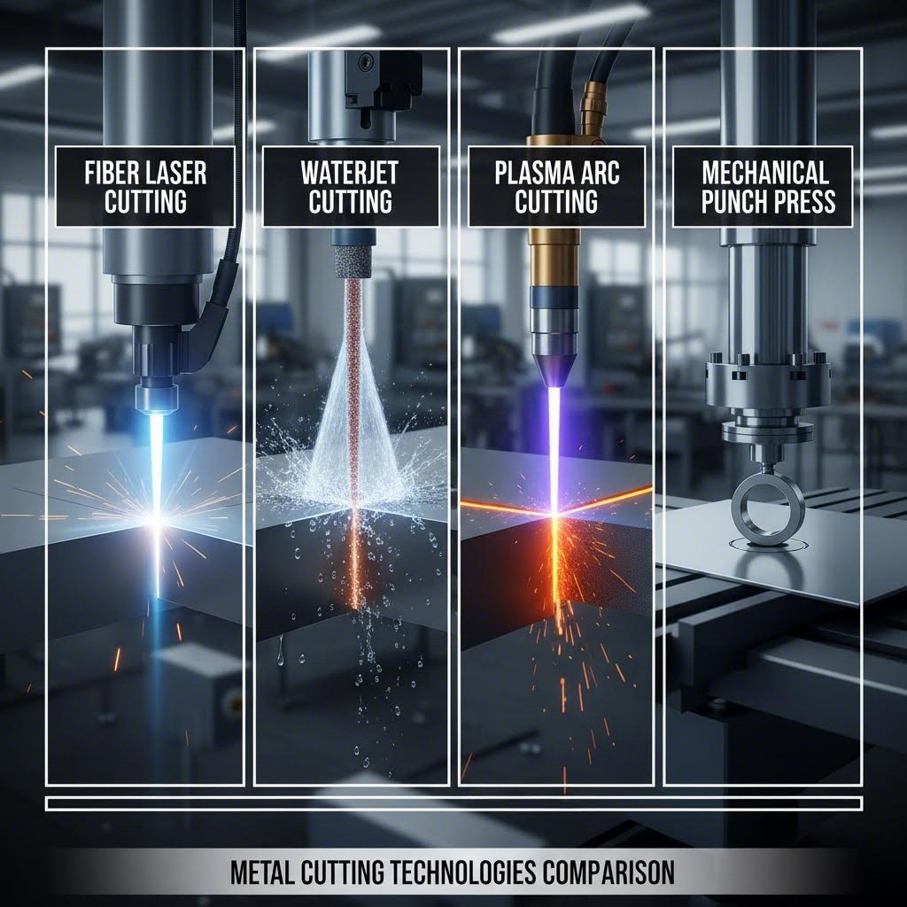
Cutting Technologies Compared From Laser to Waterjet
Now that you understand why tolerances matter, the next question becomes: which cutting technology actually delivers the precision your project demands? The answer depends on your material, thickness requirements, and quality expectations. Let's break down the four primary precision cutting technologies—each with distinct advantages that make them ideal for specific applications.
Laser Cutting Technologies Explained
When fabricators discuss laser cutting, they're typically referring to one of three distinct technologies: CO2 lasers, fiber lasers, or crystal lasers. Each uses concentrated light energy to melt and vaporize material, but the similarities largely end there.
Fiber lasers have become the dominant choice for precision sheet metal cutting in modern fabrication shops. Operating at a shorter wavelength than CO2 systems, fiber lasers produce a more focused beam with a narrower kerf—typically 0.004" to 0.008" (0.1mm to 0.2mm). According to industry tolerance data, fiber lasers can achieve tolerances as tight as ±0.001" on stainless steel, making them the precision champion for thin to medium-thickness metals.
CO2 lasers remain valuable for specific applications, particularly when cutting non-metals or thicker materials. These systems can achieve tolerances as low as ±0.002" and excel at processing wood, acrylic, and similar materials. If you're wondering how to cut plexiglass with precision, CO2 laser systems deliver clean edges without the crazing that mechanical methods often produce.
Crystal lasers (Nd:YAG and Nd:YVO) occupy a specialized niche, offering exceptional precision for very thin materials and delicate applications. UV laser variants can achieve tolerances down to ±0.0005"—extraordinary accuracy for micro-machining applications.
The laser cutter's primary advantage lies in speed combined with precision. A 6kW fiber laser can slice through 1-inch mild steel plate while maintaining excellent edge quality. For thinner materials under 0.25" (6.35mm), cutting speeds become remarkably fast without sacrificing dimensional accuracy.
Waterjet Plasma and Mechanical Cutting Methods
Waterjet cutting takes a fundamentally different approach—it uses cold supersonic abrasive erosion rather than heat. A highly pressurized water stream carrying garnet abrasive particles erodes material at approximately 60,000 PSI. This cold-cutting process eliminates heat-affected zones entirely, making waterjet ideal for materials sensitive to thermal distortion.
According to cutting process comparisons, waterjet machines achieve average tolerances of ±0.003" to ±0.005" while handling thicknesses up to 4" (100mm) of steel. The versatility is remarkable—the same machine that cuts titanium can also handle glass, ceramic tile, marble, and granite. How do you cut perspex without melting or cracking it? Waterjet provides a heat-free solution with smooth edges.
Plasma cutting uses ionized gas heated to 20,000-50,000 degrees Fahrenheit, making it exceptionally fast for electrically conductive metals. However, this speed comes with trade-offs. Plasma tolerances typically range from ±0.030" to ±0.060"—significantly looser than laser or waterjet methods. The intense heat also creates a pronounced heat-affected zone and often requires secondary finishing to achieve acceptable edge quality.
Mechanical cutting methods include shearing, punching, and CNC routing. Punching can achieve tolerances around ±0.005" to ±0.010" for high-volume production, while CNC milling offers excellent precision (±0.0003") but at slower speeds. These methods generate no heat-affected zone and work well for specific geometries and production volumes.
| Cutting Method | Typical Tolerance | Thickness Range | Edge Quality | Heat-Affected Zone | Relative Speed |
|---|---|---|---|---|---|
| Fiber Laser | ±0.001" to ±0.003" | Up to 1" steel | Excellent | Minimal | Very Fast |
| CO2 Laser | ±0.002" to ±0.005" | Up to 0.5" steel | Excellent | Minimal | Fast |
| Waterjet | ±0.003" to ±0.010" | Up to 4" steel | Good | None | Moderate |
| Plasma | ±0.030" to ±0.060" | Up to 6" aluminum | Fair | Significant | Very Fast |
| Punching | ±0.005" to ±0.010" | Thin sheets only | Fair | None | Very Fast (batch) |
| CNC Milling | ±0.0003" to ±0.001" | Varies by setup | Excellent | None | Slow |
Selecting the right metal cutter ultimately depends on balancing precision requirements against material properties and project economics. Fiber lasers dominate for thin to medium metals requiring tight tolerances. Waterjet wins when thermal distortion is unacceptable or when cutting thick materials and non-metals. Plasma makes sense for heavy plate work where speed matters more than edge finish. Mechanical methods excel in high-volume production with consistent geometries.
Understanding kerf width—the amount of material removed during cutting—also influences your technology choice. Laser systems produce the narrowest kerf (0.004" to 0.015"), followed by waterjet (0.030" to 0.040"), with plasma generating the widest kerf (0.060" to 0.150"). Narrower kerf means tighter nesting of parts and less material waste.
With these technologies understood, the next critical consideration becomes material-specific: how do aluminum, stainless steel, and specialty metals each respond to these cutting methods?
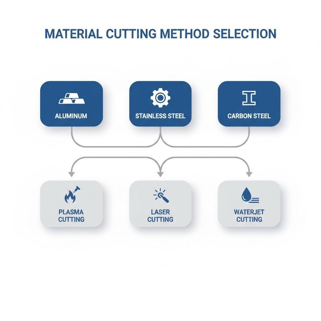
Material-Specific Cutting Methods and Thickness Limitations
Different metals behave in dramatically different ways when exposed to cutting processes. The thermal conductivity of aluminum sheet metal causes heat to dissipate rapidly—completely unlike how stainless steel sheet concentrates thermal energy at the cut zone. Understanding these material-specific behaviors helps you select the optimal cutting method and avoid costly mistakes before production begins.
Imagine running identical cutting parameters on two different metals. What works perfectly for carbon steel plate might produce disastrous results on an aluminum sheet. That's because each material brings unique challenges: reflectivity, thermal properties, hardness, and oxide formation all influence cutting performance and achievable tolerances.
Aluminum and Stainless Steel Cutting Considerations
Aluminum sheet metal presents a fascinating challenge for precision cutting. This material's exceptionally high thermal conductivity—approximately 205 W/m·K compared to steel's 50 W/m·K—means heat disperses quickly away from the cut zone. While this reduces heat-affected zones, it also requires higher power input to maintain cutting temperature.
The bigger hurdle? Reflectivity. According to cutting process research, aluminum strongly reflects laser energy, particularly at CO2 wavelengths (10.6 µm). This reflection can damage optical components and reduce cutting efficiency dramatically. Fiber lasers operating at shorter wavelengths (around 1.06 µm) handle metals aluminium far more effectively, making them the preferred choice for precision aluminum work.
- Fiber laser cutting: Best for aluminum 0.5mm to 15mm; specialized high-power systems can handle up to 25mm with excellent edge quality
- Waterjet cutting: Ideal for thicker aluminum plate (up to 100mm) where heat distortion is unacceptable; eliminates reflectivity concerns entirely
- Plasma cutting: Effective for aluminum above 6mm; produces faster cuts but rougher edges requiring secondary finishing
- CO2 laser: Possible but requires special optics and coatings; generally less effective than fiber systems for aluminum
Stainless steel sheet metal responds quite differently to cutting processes. Its lower thermal conductivity actually works in your favor—heat stays concentrated at the cut zone, enabling cleaner cuts with minimal heat-affected zones. According to steel cutting research, austenitic stainless steels like 304 and 316 stainless steel respond exceptionally well to laser cutting due to their consistent composition and thermal properties.
- Fiber laser cutting: Achieves tolerances as tight as ±0.001" on stainless steel sheet; handles thicknesses from 0.5mm to 25mm depending on power
- Waterjet cutting: Excellent for 316 stainless steel applications requiring zero thermal distortion; effective up to 100mm thickness
- Plasma cutting: Produces wider heat-affected zones on stainless; best reserved for thicker materials where edge finish is secondary
- Mechanical punching: Works well for thin gauge stainless in high-volume production; maintains tight tolerances without thermal effects
Carbon Steel and Specialty Metal Requirements
Carbon steel remains the most forgiving material for precision cutting. Common structural grades like A36 and A572 steel plate produce clean cuts across virtually all cutting technologies. However, carbon content significantly influences cutting behavior—low-carbon steels (under 0.3% carbon) cut more predictably than high-carbon alternatives.
Surface condition matters tremendously for carbon steel. Clean, scale-free surfaces consistently produce better results than rusty or oxidized material. When working with galvanized sheet metal, the zinc coating can affect cut quality and produce fumes requiring proper ventilation systems.
- Oxy-fuel cutting: Excellent for thick carbon steel plate above 12mm; most economical method for heavy sections
- Fiber laser cutting: Optimal for thin to medium carbon steel (up to 25mm); achieves tight tolerances with excellent edge quality
- Plasma cutting: Fast and cost-effective for carbon steel 6mm to 50mm; acceptable edge quality for structural applications
- Waterjet cutting: Preferred when heat-affected zones cannot be tolerated; effective across all thickness ranges
Specialty metals demand careful cutting method selection based on their unique properties:
- Titanium: Waterjet preferred to avoid alpha-case formation from thermal cutting; fiber laser possible with inert gas shielding
- Copper alloys: High reflectivity challenges similar to aluminum; fiber lasers with higher power settings work best for thin gauges
- Tool steels: Require slower cutting speeds and potential preheating to prevent edge hardening and cracking
- Nickel alloys: Laser cutting effective but may require reduced speeds; excellent candidates for waterjet when precision is critical
Material thickness directly dictates which cutting method makes practical sense. Fiber lasers dominate the thin-to-medium range (under 25mm) across most metals. Waterjet becomes increasingly attractive as thickness exceeds 12mm where thermal methods struggle. Plasma excels for heavy plate work where speed outweighs edge quality concerns. For very thin materials under 1mm, mechanical methods or specialized micro-laser systems may outperform standard approaches.
With material selection understood, the next critical step involves designing your parts to maximize cutting precision—because even the best cutting technology cannot overcome fundamentally flawed design decisions.
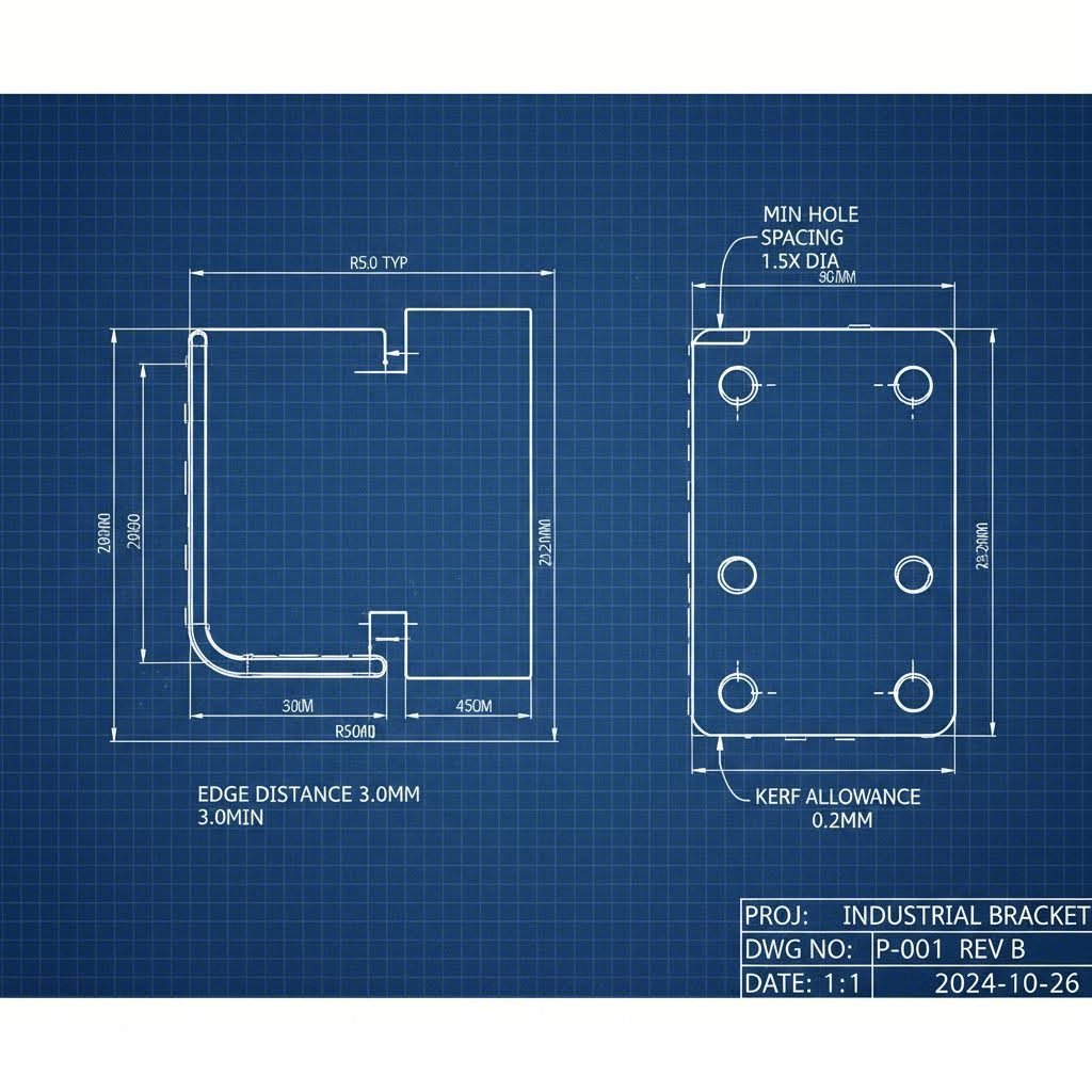
Design Best Practices for Achieving Precision Cuts
You've selected your material and identified the right cutting technology—but here's the reality check: even the most advanced fiber laser cannot salvage a poorly designed part. Precision sheet metal fabrication begins on the drafting table, not on the shop floor. The decisions you make during design directly determine whether your parts achieve target tolerances or require expensive rework.
Think about it this way: specifying a 0.020" hole in 0.125" steel plate positioned 0.010" from the edge might look fine on screen. But that design violates fundamental manufacturing constraints that no cutting method can overcome. Understanding kerf allowances, minimum feature sizes, and proper spacing requirements transforms theoretical designs into manufacturable precision components.
Kerf Allowances and Minimum Feature Sizes
Kerf—the width of material removed during cutting—varies dramatically between technologies. According to cutting kerf research, laser cutting produces a kerf of approximately 0.3mm (0.012"), while plasma cutting generates kerfs around 3.8mm (0.150"). This difference has massive implications for precision sheet metal forming and dimensional accuracy.
Why does kerf matter for your design? Imagine cutting a 600mm x 600mm square. If the cutting path follows your exact lines, the finished part will be smaller than specified by half the kerf width on each edge. For laser cutting, that's roughly 0.15mm per side—acceptable for most applications. For plasma cutting at 3.8mm kerf, you'd lose nearly 2mm per side, resulting in a 596mm x 596mm part.
Here's how kerf width breaks down by cutting method:
| Cutting Method | Typical Kerf Width | Design Impact |
|---|---|---|
| Fiber Laser | 0.004" - 0.015" (0.1 - 0.4mm) | Minimal compensation needed; enables tight nesting |
| CO2 Laser | 0.006" - 0.020" (0.15 - 0.5mm) | Standard compensation; excellent for most applications |
| Waterjet | 0.030" - 0.040" (0.75 - 1.0mm) | Moderate compensation; consider for tight-tolerance features |
| Plasma | 0.060" - 0.150" (1.5 - 3.8mm) | Significant compensation required; avoid fine features |
| Oxy-Fuel | 0.040" - 0.060" (1.0 - 1.5mm) | Material thickness dependent; increases with thicker plate |
Minimum feature sizes depend on both material thickness (MT) and your chosen cutting method. According to design guidelines from Xometry, these critical dimensions ensure reliable, repeatable results when fabricating sheet metal:
- Minimum hole diameter: Should equal at least 1x material thickness, with 0.040" (1mm) as the absolute minimum for laser/waterjet
- Minimum slot width: 0.040" or 1x material thickness, whichever is greater
- Minimum tab thickness: 0.063" or 1x material thickness, whichever is greater
- Minimum relief cuts: 0.010" or 1x material thickness, whichever is greater
When working with common materials, consult a sheet metal gauge chart to understand your actual thickness. For example, 14 gauge steel thickness measures 0.0747" (1.9mm)—meaning your minimum slot width would be 0.0747" rather than the 0.040" floor. Getting these relationships wrong during design leads to features that either cannot be cut or fail during use.
Design Rules for Optimal Edge Quality
Edge quality expectations vary by cutting method and downstream requirements. CNC sheet metal fabrication using fiber lasers typically produces edges requiring no secondary finishing for cosmetic applications. Plasma-cut edges almost always require grinding or machining to achieve comparable finish quality.
Corner radii represent one of the most commonly overlooked design constraints. Sharp internal corners are physically impossible—every cutting method leaves some radius based on the beam, stream, or tool diameter. Specify internal corner radii of at least 0.5x material thickness or 0.125" (3.2mm), whichever is smaller, to ensure manufacturability.
Hole-to-edge and hole-to-hole spacing critically affect both cutting quality and part strength. Position holes too close to edges, and the remaining material may distort during cutting or fail under load. The following checklist provides engineers with proven design practices for specifying precision cuts:
- Verify minimum hole-to-edge distance: Maintain at least 2x material thickness or 0.125" (3.2mm), whichever is smaller, between any hole perimeter and the part edge
- Check hole-to-hole spacing: Keep at least 6x material thickness or 0.125" between adjacent holes to prevent thermal distortion and maintain structural integrity
- Specify appropriate corner radii: Use minimum 0.5x material thickness for internal corners; smaller radii require slower cutting speeds and may compromise edge quality
- Account for kerf compensation: Dimension your drawings to nominal finished sizes—let the fabricator apply appropriate kerf offsets based on their equipment
- Explode text and verify outlines: Convert all text to shapes with cutting paths; add stencil bridges to enclosed letters (D, O, P, Q, R, A, B) to prevent fallout
- Use standard gauge thicknesses: Design around readily available material sizes to prevent sourcing delays and cost premiums
- Include relief cuts at inside corners: Where bends meet cut edges, add small relief cuts (minimum 0.010" or 1x MT) to prevent tearing
- Specify grain direction requirements: If bend orientation or strength matters, indicate whether grain should run parallel or perpendicular to critical features
- Add lollipop rounds to narrow slots: Exaggerated radii at slot ends compensate for larger pierce holes, especially in plasma and waterjet cutting
- Define critical versus standard tolerances: Identify which dimensions require tight tolerance control and which can accept standard fabrication tolerances
Proper design preparation directly impacts achievable tolerances—and your bottom line. A part designed with appropriate feature sizes, spacing, and corner radii cuts faster, produces fewer rejects, and requires less secondary finishing. Conversely, designs that violate these guidelines force fabricators to slow cutting speeds, increase scrap rates, and add manual finishing operations.
The relationship between design and edge quality extends beyond cutting to downstream processes. Parts destined for powder coating or anodizing require different edge preparations than those heading to welding stations. Sharp burrs interfere with coating adhesion, while excessive rounding may affect fit-up during assembly.
Now that your designs account for manufacturing constraints, understanding what happens at cut edges—heat-affected zones, surface finish expectations, and quality standards—becomes the next critical knowledge area.
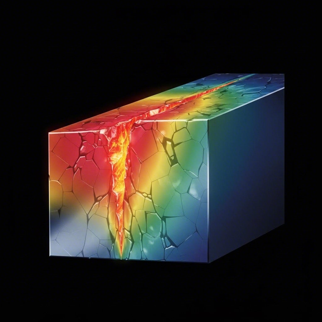
Edge Quality Heat-Affected Zones and Surface Finish Standards
Your design is optimized, your cutting method selected—but what actually happens to the metal at the cut edge? This is where thermal cutting methods reveal their hidden impact. The intense heat that makes laser and plasma cutting so effective also transforms the material properties near every cut edge. Understanding these changes helps you predict performance, specify appropriate finishing operations, and avoid costly failures downstream.
Think about what happens when you slice through steel with a focused laser beam at thousands of degrees. The metal doesn't simply separate—it undergoes rapid heating, melting, and cooling cycles that fundamentally alter its microstructure. These changes extend beyond the visible cut edge into what engineers call the heat-affected zone.
Understanding Heat-Affected Zones in Thermal Cutting
According to TWI Global's technical research, the heat-affected zone (HAZ) is a non-melted area of metal that has undergone changes in material properties as a result of being exposed to high temperatures. This zone sits between the actual cut edge and the unaffected parent metal—and its characteristics directly impact your part's tensile strength, hardness, and corrosion resistance.
Why should you care about HAZ? Consider a precision component that requires subsequent bending operations. If the HAZ extends too far into the material, you may encounter unexpected cracking or work hardening at the bend line. Parts destined for high-stress applications may exhibit reduced fatigue life near cut edges. Components requiring welding may experience different fusion characteristics in the HAZ region.
The size of the heat-affected zone depends on several interrelated factors:
- Thermal diffusivity: Materials with high thermal conductivity (like aluminum) transfer heat faster, resulting in narrower HAZ widths. Lower conductivity materials (like stainless steel) retain heat longer, potentially producing wider affected zones.
- Heat input: Higher power settings and slower cutting speeds increase total heat energy transferred to the workpiece, expanding the HAZ.
- Cutting process: Each method produces dramatically different HAZ characteristics based on its operating temperature and speed.
- Material thickness: Thicker materials act as larger heat sinks, often cooling faster and reducing HAZ width compared to thin sheets cut at identical parameters.
How do different cutting methods compare? According to comprehensive cutting technology analysis, the differences are substantial. Waterjet cutting produces zero HAZ because no heat is applied—the cold supersonic abrasive stream simply erodes material without thermal effects. Laser cutting creates a minimal HAZ due to heat being concentrated in a very small area with rapid cutting speeds. Plasma cutting generates an intermediate HAZ, though higher current settings enable faster speeds that can narrow the affected zone. Oxy-acetylene cutting produces the widest HAZ due to high heat, slower speeds, and broader flame width.
For precision applications, the HAZ implications extend beyond immediate cut quality. Parts requiring anodizing or other surface treatments may show differential coloration in the HAZ region. Components needing powder coat finishes may exhibit adhesion variations where material properties have changed. Understanding these downstream effects helps you specify appropriate cutting methods from the start.
Surface Finish Standards and Edge Quality Grades
Edge quality encompasses more than just the heat-affected zone—it includes surface roughness, dross formation, burr presence, and overall dimensional accuracy. Each cutting method produces characteristic edge qualities that determine whether secondary finishing is required.
To define dross clearly: it's the resolidified metal that adheres to the bottom edge of thermal cuts. When molten material isn't completely expelled from the cut zone, it cools and bonds to the workpiece, creating rough, irregular deposits that must be removed before subsequent operations. Dross formation increases with cutting speed beyond optimal parameters, inadequate assist gas pressure, or worn consumables.
Surface roughness is measured using Ra values—the arithmetic average of surface height deviations from the mean line, expressed in microinches (µin) or micrometers (µm). Lower Ra values indicate smoother surfaces. Industry standards vary by application:
- Aerospace components: Often require Ra 32 µin (0.8 µm) or better
- Medical devices: Typically specify Ra 16-63 µin (0.4-1.6 µm) depending on function
- Automotive stamping: Generally accept Ra 63-125 µin (1.6-3.2 µm)
- General fabrication: Ra 125-250 µin (3.2-6.3 µm) is typically acceptable
| Cutting Method | Edge Quality Rating | Typical Ra Value | Dross Formation | Burr Presence | Secondary Finishing Required |
|---|---|---|---|---|---|
| Fiber Laser | Excellent | 32-63 µin (0.8-1.6 µm) | Minimal to none | Minimal | Rarely needed |
| CO2 Laser | Excellent | 63-125 µin (1.6-3.2 µm) | Light | Minimal | Occasionally needed |
| Waterjet | Good to Excellent | 63-250 µin (1.6-6.3 µm) | None | None | Speed-dependent |
| Plasma | Fair | 250-500 µin (6.3-12.5 µm) | Moderate to heavy | Moderate | Usually required |
| Oxy-Fuel | Fair | 250-500 µin (6.3-12.5 µm) | Heavy | Heavy | Always required |
| Mechanical Punching | Good | 63-125 µin (1.6-3.2 µm) | None | Present (one side) | Deburring typically needed |
When is secondary finishing required? The answer depends on your downstream processes and final application. Parts destined for visible assemblies often require edge deburring and surface refinement regardless of cutting method. Components heading to powder coat lines need clean, burr-free edges for proper coating adhesion. Anodized aluminum parts demand consistent surface preparation to achieve uniform coloration across cut and uncut surfaces.
Burr formation presents different challenges than dross. While dross adheres to the bottom surface of thermal cuts, burrs are thin ridges of displaced material pushed beyond the intended cut edge. Mechanical cutting methods like punching create predictable burrs on one side—the die side—which can be managed through proper die clearance and maintenance. Thermal methods may create micro-burrs from resolidified material at cut edges.
For precision applications, understanding these edge quality characteristics helps you build realistic expectations and budget appropriately for finishing operations. A plasma-cut part requiring cosmetic edges will need grinding, deburring, and potentially additional surface treatment—all adding cost and lead time. Laser-cut equivalents may proceed directly to assembly or coating with minimal preparation.
Edge quality also influences mechanical performance. Rough cut edges with significant dross act as stress concentrators, potentially reducing fatigue life in cyclic loading applications. Parts with demanding tensile strength requirements may need edge conditioning to remove microstructural anomalies introduced during cutting. HAZ regions may exhibit altered hardness profiles that affect wear resistance or formability.
With edge quality expectations established, the next consideration becomes identifying and preventing the defects that compromise precision cutting—because even optimized processes occasionally produce problems requiring troubleshooting.
Troubleshooting Cutting Defects and Quality Verification
Even with optimized parameters and proper design practices, precision sheet metal cutting occasionally produces defects that compromise part quality. The difference between a precision metal fabricator and an average shop often comes down to how quickly problems are identified, diagnosed, and corrected. Understanding common defect types—their root causes and prevention strategies—transforms reactive troubleshooting into proactive quality assurance.
When a part comes off the cutting table with dimensional errors or poor edge quality, the clock starts ticking. Every minute spent diagnosing the problem means delayed production and potential scrap accumulation. That's why experienced fabricators develop systematic approaches to defect identification and resolution.
Common Cutting Defects and Root Causes
According to industry troubleshooting research, these defects account for the majority of precision cutting quality issues. Each defect type has specific causes requiring targeted solutions:
- Taper (angular deviation): Cut edges that aren't perpendicular to the material surface, creating parts that are wider at the top than bottom or vice versa. Primary causes include beam or nozzle misalignment, worn cutting tips, and variance in material thickness. Solutions involve recalibrating the machine regularly, setting specific kerf values per material inside your CAM tool, and prototyping first cuts before mass production.
- Dross adhesion: Molten material clinging to the underside of cuts, interfering with fitment and requiring manual cleanup. This occurs when assist gas pressure runs too low, nozzle height or focus drifts off-spec, or material thickness exceeds current parameters. Adjust cutting head standoff distance, boost assist gas pressure, and use elevated cutting supports (slats or grids) to let dross fall cleanly.
- Thermal distortion (warping): Flat sheets curling like potato chips, especially problematic with thin aluminum or stainless steel. Heat buildup during laser or plasma cutting, insufficient support, and thin gauge stock with tight corner radii all contribute. Use pulsed laser cutting to minimize heat input, switch to waterjet cutting for zero-heat edge cuts, or apply sacrificial backing plates for support.
- Burr formation: Jagged edges or raised material ridges that should be clean and sharp, particularly common with laser and plasma operations. Worn nozzles or lenses, excessive cutting speed, beam misalignment, and incorrect focus distance cause most burrs. Recalibrate your laser cutting machine or CNC tool path, check lens and nozzle condition, and slow down feedrate or adjust assist gas settings.
- Dimensional inaccuracy: Holes slightly off position or sheet lengths shorter than specified—variations that prevent proper part fitment. Poor fixturing, machine backlash, thermal distortion, and CAM settings not compensating for kerf all contribute. Use proper clamps, jigs, or vacuum tables to hold thin sheets flat, compensate for kerf width in your CAD/CAM software, and slow cutting speed on thermally sensitive metals.
- Burn marks or discoloration: Scorched surfaces instead of smooth silver cuts, especially around corners or tight geometry. Excess heat from overpowered laser settings, using oxygen assist gas (which oxidizes surfaces), and dirty or low-grade material cause discoloration. Use nitrogen or argon assist gas to avoid oxidized edges, reduce laser power or use multiple low-pulse passes, and perform test cuts before running full jobs.
- Poor surface finish: Rough edges, visible striations, or inconsistent cut lines even when dimensions are technically correct. Dirty optics (for lasers), wrong feed rate/speed combinations, and mechanical vibration in the gantry create finish problems. Clean the lens, mirrors, and collimator regularly, use dampers or weighted tables to minimize vibration, and tune cutting parameters specifically for your material thickness.
Just as a precision fabricator consults a drill bit size chart or drill size chart to match tooling to applications, matching cutting parameters to specific materials and thicknesses prevents most defects before they occur. The key lies in systematic parameter documentation and consistent machine maintenance.
Prevention Strategies for Quality Assurance
Preventing defects costs far less than correcting them. According to quality inspection research, modern sheet metal inspection integrates directly with manufacturing equipment for closed-loop quality control. Statistical process control (SPC) software analyzes measurement data to identify trends and prevent defects before they occur.
Quality verification for high precision metal parts employs multiple inspection technologies, each suited to specific measurement needs:
- Coordinate Measuring Machines (CMM): Precision instruments using touch probes to collect 3D coordinate data from parts. Capable of measuring complex geometries with micron-level accuracy, CMMs verify critical dimensions against CAD models and generate comprehensive deviation reports.
- Optical measurement systems: Non-contact systems using high-resolution cameras, structured light, or laser scanning to capture complete 3D profiles. These systems process hundreds of measurements in seconds, comparing them against CAD models with micron-level precision while eliminating operator influence.
- Go/no-go gauging: Simple, fast verification tools that check whether features fall within acceptable tolerance ranges. Pin gauges verify hole diameters, step gauges check thickness, and contour gauges verify edge profiles—all without complex measurement setup.
- Surface roughness testers: Specialized instruments quantifying surface texture using diamond-tipped stylus or optical methods, providing numerical Ra values for quality control documentation.
- Optical comparators: Project magnified part profiles onto screens with overlay templates for rapid visual comparison, effective for checking 2D contours, hole patterns, and edge conditions.
Metal precision depends on consistent verification throughout production—not just final inspection. First article inspection validates that initial parts meet specifications before full production runs. In-process gauging provides real-time feedback enabling immediate parameter adjustments. Final inspection confirms that completed parts meet all dimensional and surface quality requirements.
The combination of defect prevention strategies and systematic quality verification separates professional precision fabricator operations from shops that rely on trial and error. When cutting parameters are documented, machines are maintained, and inspection protocols are followed consistently, defect rates drop dramatically while throughput increases.
With quality assurance systems in place, the final consideration becomes matching all these factors—technology, material, design, and quality requirements—into a coherent decision framework for selecting the right cutting method for your specific application.
Selecting the Right Cutting Method for Your Application
You've absorbed the technical details—tolerances, materials, edge quality, defect prevention. Now comes the practical question every engineer and procurement team faces: which cutting method actually makes sense for your specific project? The answer rarely comes down to a single factor. Instead, it requires balancing tolerance requirements, material properties, production volume, and budget constraints into a coherent decision.
Think of method selection as solving a multi-variable equation. A custom metal signs project requiring intricate detail in thin aluminum demands a completely different approach than heavy steel plate destined for structural assemblies. The cutting technology that optimizes one set of requirements may prove entirely wrong for another.
Matching Your Project Requirements to Cutting Methods
According to CNC cutting method research, factors such as material type, required tolerances, production volume, and budget constraints all play crucial roles in determining which cutting method fits best. The following step-by-step decision process guides you through these interconnected considerations:
- Define your tolerance requirements first. Ask yourself: does your application demand ±0.001" precision, or will ±0.030" work perfectly fine? Tight tolerances (±0.005" or better) immediately narrow your options to fiber laser, waterjet, or CNC milling. Looser requirements open the door to plasma cutting and oxy-fuel methods that offer significant cost advantages for appropriate applications.
- Identify your material and thickness range. Match your metal plate or sheet to compatible technologies. Thin stainless steel under 6mm? Fiber laser dominates. Thick aluminum above 25mm? Waterjet handles it without thermal distortion. Carbon steel plate beyond 50mm? Plasma or oxy-fuel becomes practical. Reflective materials like copper or brass require fiber lasers with specialized parameters or waterjet cutting.
- Evaluate edge quality needs against downstream processes. Parts heading to visible assemblies or powder coating lines need clean, burr-free edges—fiber laser delivers without secondary finishing. Components destined for structural welding can tolerate plasma-cut edges that would be unacceptable for cosmetic applications.
- Consider heat-affected zone implications. Will your parts undergo subsequent bending, heat treatment, or surface finishing? If HAZ creates problems, waterjet eliminates thermal effects entirely. For less critical applications, laser cutting's minimal HAZ poses no practical concerns.
- Assess geometric complexity. Intricate patterns, tight internal corners, and fine details favor laser cutting's narrow kerf and precise beam control. Simple rectangular cuts or straight-line geometry don't require laser precision—consider whether simpler methods could reduce costs.
- Match production volume to technology economics. This step often overrides pure technical considerations. A method that's optimal for one quantity may be entirely wrong for another.
Volume and Budget Considerations for Method Selection
Production volume fundamentally changes the economics of cutting method selection. According to prototyping and production research, understanding the difference between prototyping and production machining is crucial for accuracy and efficiency. What works for proving a design rarely optimizes high-volume manufacturing.
Prototyping requirements (1-50 pieces): Speed and flexibility matter more than per-piece cost. Waterjet and laser cutting excel here because they require no tooling investment and can cut revised designs within hours of receiving updated files. Testing precision requirements before committing to production tooling prevents expensive mistakes. If you're searching for "metal fabrication near me" or "fabrication shops near me" for prototype work, prioritize shops with quick-turn capabilities and diverse equipment over high-volume specialists.
Low-volume production (50-500 pieces): Per-piece economics start mattering, but tooling investments still can't be amortized effectively. Laser cutting typically offers the best balance—fast enough for reasonable lead times, precise enough for demanding tolerances, and cost-effective without requiring dedicated tooling. Steel fabrication in this range benefits from laser's speed advantage over waterjet.
Medium-volume production (500-5,000 pieces): Hybrid approaches often make sense. Consider laser cutting for complex features combined with punching for simple holes—leveraging each technology's strengths. Tooling investments for progressive dies or specialized fixtures begin paying dividends at these quantities.
High-volume production (5,000+ pieces): Dedicated tooling and optimized processes justify significant upfront investment. Progressive die stamping may outperform laser cutting on per-piece cost despite higher initial tooling expense. When searching for "metal fabricators near me" for production quantities, evaluate their automation capabilities and capacity for consistent long-run quality.
Budget constraints interact with volume in predictable ways:
- Lowest initial cost: Plasma cutting offers the cheapest entry point for thick materials, with equipment and operating costs well below laser systems
- Lowest per-piece cost at volume: Mechanical punching and stamping win when quantities justify tooling investment
- Best value for mixed requirements: Fiber laser systems balance precision, speed, and operating costs across diverse applications
- Premium for zero thermal effects: Waterjet commands higher per-piece costs but eliminates HAZ-related quality issues and secondary processing
When does combining multiple methods make sense? Hybrid approaches work when different features have different requirements. A metal plate component might benefit from waterjet cutting for heat-sensitive edges while using laser cutting for intricate internal features. Complex assemblies might combine stamped high-volume components with laser-cut custom brackets.
The decision framework ultimately requires honest assessment of what actually matters for your application. Specifying tighter tolerances than necessary inflates costs without adding value. Choosing looser tolerances than function requires creates assembly problems and field failures. Matching your genuine requirements—not worst-case assumptions—to appropriate technology delivers optimal results at reasonable cost.
With your cutting method selected, the final consideration becomes finding the right fabrication partner—one with the equipment, certifications, and expertise to deliver precision results consistently.
Partnering with Precision Sheet Metal Fabricators
You've defined your tolerances, selected the right cutting technology, and optimized your design for manufacturability. Now comes the decision that determines whether all that preparation pays off: choosing the right precision sheet metal fabricator to execute your vision. The gap between a mediocre shop and a true precision partner can mean the difference between parts that assemble flawlessly and components requiring costly rework.
Think about it this way: even the most advanced fiber laser system produces inconsistent results in the hands of an inexperienced operator. Conversely, a skilled metal fab team with proper quality systems can coax exceptional precision from standard equipment. Finding the right partner requires evaluating capabilities, certifications, and communication practices—not just quoted prices.
What to Look for in a Precision Cutting Partner
According to industry research on contract fabrication, evaluating potential partners requires assessment across multiple dimensions. Equipment age and technology matter—modern fiber laser systems cut 2-3x faster than older CO2 lasers and handle reflective materials that older systems struggle with. But equipment alone doesn't guarantee results.
Here's what separates precision sheet metal fabricators from general job shops:
- Equipment and technology alignment: Verify the fabricator operates equipment suited to your materials and tolerances. Ask about machine age, maintenance schedules, and backup capacity. Shops with multiple machines can accommodate production surges without schedule disruptions.
- Secondary services integration: Steel fabricators offering welding, finishing, and hardware installation provide single-source convenience. However, verify each capability's quality independently—not all shops excel at everything. Ask specifically about powder coating services and aluminum welding if your project requires these operations.
- Design for Manufacturability (DFM) expertise: Experienced precision fabricator teams identify design issues causing manufacturing problems, quality defects, or unnecessary costs. Industry guidance emphasizes that DFM review should be standard practice during quoting, not an optional service. Partners with strong DFM support help optimize designs for precision cutting before production begins.
- Prototype through production capability: Manufacturers handling prototype quantities (1-10 pieces) through mid-volume production (100-5,000+) provide consistency across your product lifecycle. Switching fabricators between prototype and production introduces quality and timeline risks.
- Inspection capabilities: CMM inspection, optical comparators, and calibrated measurement equipment enable first article inspection and ongoing dimensional verification. Ask about equipment capacity and calibration frequency.
- Customer references and longevity: Request 3-5 customer contacts in similar applications and production volumes. Companies operating 20+ years demonstrate sustained market competitiveness. Ask references about communication quality, problem resolution, and delivery performance.
Geographic considerations also matter. Multi-site manufacturers provide redundancy against weather disruptions or equipment failures. Local fabricators offer communication convenience and site visit accessibility. Evaluate whether proximity provides meaningful operational value for your specific requirements, or whether superior capabilities at a distant facility outweigh logistics considerations.
Certifications and Quality Standards That Matter
Quality certifications provide objective evidence that a fabricator maintains documented procedures, corrective action processes, and management review systems. But not all certifications carry equal weight for precision applications.
ISO 9001:2015 demonstrates quality management system maturity across manufacturing operations. According to certification research, this standard establishes baseline expectations for documented procedures, process control, and continuous improvement. Most professional precision sheet metal fabricators maintain ISO 9001 certification as a minimum qualification.
IATF 16949:2016 represents the gold standard for automotive supply chain manufacturing. According to IATF certification research, this specialized standard was drafted by the International Automotive Task Force to harmonize quality assessment systems throughout the global automotive industry. IATF 16949 creates a baseline for quality you can expect when contracting precision work—its literature focuses specifically on prevention of defects and production variances, as well as minimizing scrap and waste.
The three primary aims of IATF 16949 certification include improving both quality and consistency of products and manufacturing processes, establishing "supplier of choice" status amongst leading manufacturers through proven accountability, and integrating seamlessly with industry-wide ISO certification standards. For chassis, suspension, and structural components requiring automotive-grade precision, IATF 16949 certification ensures your fabrication partner meets rigorous quality requirements.
Industry-specific certifications indicate experience with regulated manufacturing:
- AS9100: Aerospace quality management requirements
- ISO 13485: Medical device manufacturing standards
- ITAR registration: Defense-related manufacturing authorization
Beyond certifications, request quality performance metrics directly. Established manufacturers track defect rates, on-time delivery performance, and customer satisfaction scores systematically. Evasive responses suggest quality issues that certifications alone won't reveal.
Rapid prototyping capabilities prove particularly valuable for testing precision requirements before committing to production quantities. A fabrication partner offering 5-day rapid prototyping can validate that your design achieves target tolerances with actual cut parts—not just theoretical calculations. This prototyping phase catches design issues early when corrections cost least.
Quote turnaround time indicates operational efficiency and customer focus. Partners providing 12-hour quote turnaround demonstrate streamlined engineering review processes and capacity to respond quickly. Complex assemblies requiring weld time estimation and DFM analysis naturally need longer evaluation periods, but simple parts should quote within days, not weeks.
For automotive applications requiring precision sheet metal cutting with certified quality systems, Shaoyi (Ningbo) Metal Technology delivers IATF 16949-certified manufacturing from rapid prototyping through automated mass production. Their comprehensive DFM support helps optimize designs before cutting begins, while 12-hour quote turnaround accelerates your supply chain decisions.
Effective fabrication partnerships require strong communication infrastructure beyond certifications. Look for dedicated project management providing single points of contact, production visibility through regular status updates, and direct engineering accessibility for DFM discussions and manufacturing problem solving. The responsiveness you experience during quoting typically mirrors future communication quality—evaluate carefully before committing.
Frequently Asked Questions About Precision Sheet Metal Cutting
1. What is the most accurate way to cut metal?
Fiber laser cutting delivers the highest accuracy for sheet metal, achieving tolerances as tight as ±0.001" on stainless steel. For applications requiring zero thermal effects, waterjet cutting provides ±0.003" to ±0.005" accuracy while eliminating heat-affected zones entirely. CNC milling can achieve ±0.0003" but operates at slower speeds. The optimal choice depends on your material thickness, tolerance requirements, and whether heat distortion is acceptable for your application.
2. How accurate is laser cutting sheet metal?
Laser cutting accuracy varies by technology and material. Fiber lasers achieve ±0.001" to ±0.003" on metals like stainless steel and aluminum, while CO2 lasers typically deliver ±0.002" to ±0.005". Factors affecting accuracy include material thickness, thermal conductivity, and cutting speed. For comparison, standard fabrication tolerances range from ±1/32" to ±1/16", making laser cutting significantly more precise for applications requiring exact specifications.
3. How much does metal laser cutting cost?
Laser cutting steel typically costs $13-$20 per hour of machine time. For a project requiring 15,000 inches of cutting at 70 inches per minute, expect approximately 3.5 hours of active cutting time. Total project costs also include material, setup, programming, and any secondary finishing. High-volume production reduces per-piece costs significantly, while prototype quantities command higher rates due to setup time. IATF 16949-certified fabricators like Shaoyi offer competitive pricing with rapid 12-hour quote turnaround.
4. What is the difference between precision sheet metal fabrication and standard fabrication?
Precision sheet metal fabrication achieves tolerances of ±0.005" to ±0.010" (±0.13mm to ±0.25mm), while standard fabrication typically maintains ±1/16" to ±1/8" (±1.6mm to ±3.2mm). The difference stems from advanced equipment like fiber lasers with micro-joint technology, sophisticated CMM measurement systems, and rigorous quality protocols. Industries like aerospace, medical devices, and automotive require precision fabrication where dimensional accuracy directly impacts safety and performance.
5. Which cutting method should I choose for my project?
Method selection depends on tolerance requirements, material type, thickness, and volume. Choose fiber laser for thin-to-medium metals requiring ±0.005" or tighter tolerances. Select waterjet when heat-affected zones are unacceptable or for materials over 25mm thick. Consider plasma for heavy plate where speed matters more than edge finish. For high-volume production exceeding 5,000 pieces, mechanical punching or stamping may offer the lowest per-piece cost despite higher tooling investment.