 Small batches, high standards. Our rapid prototyping service makes validation faster and easier —

CNC Prototyping Machine Decisions: From Material Choice To Final Part
What Makes CNC Prototyping Machines Essential for Product Development
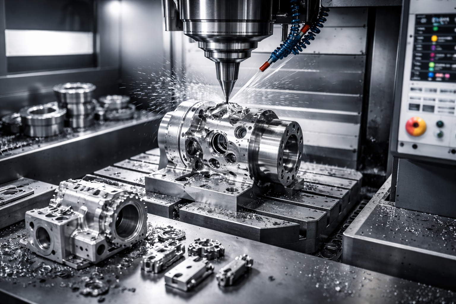
Ever wondered how engineers transform digital concepts into tangible, functional parts they can actually hold and test? That's exactly where a CNC prototyping machine comes into play. These computer-controlled systems take your CAD designs and carve them into physical reality using precision cutting tools—removing material layer by layer until your prototype emerges from a solid block of metal, plastic, or composite.
Think of it this way: you start with a digital blueprint and a raw material block. The machine reads your design specifications, calculates the exact tool movements needed, and systematically cuts away everything that isn't your part. This subtractive approach delivers prototypes with exceptional accuracy, tight tolerances, and material properties that closely match production-grade components.
From Digital Design to Physical Reality
The journey from screen to shop floor follows a straightforward path. An engineer creates a 3D model using CAD software, defining every dimension, curve, and feature. That digital file then transfers to the CNC system, where specialized programming translates geometry into precise toolpaths. Within hours—sometimes minutes—you're holding a prototype CNC part ready for testing.
What sets CNC prototyping apart from standard production machining? Speed and flexibility. While production runs prioritize efficiency at scale, cnc machining prototyping emphasizes rapid iteration. You can test a design, identify issues, modify your CAD file, and machine an updated version the same day. This iterative capability accelerates development cycles dramatically.
CNC prototyping bridges the critical gap between concept validation and production-ready manufacturing, allowing teams to test real materials under real conditions before committing to expensive tooling investments.
Why Subtractive Manufacturing Still Dominates Prototyping
Despite the explosion of 3D printing technology, subtractive rapid machining remains the preferred choice for functional prototype development. Why? The answer lies in material authenticity and mechanical performance.
When you need a cnc prototype that behaves exactly like your final production part—withstanding stress tests, thermal cycling, or impact evaluations—nothing matches CNC machining's material versatility. You can machine the same aluminum alloys, stainless steels, or engineering plastics destined for mass production. According to industry analysis, the rapid prototyping market is expected to grow at a CAGR of 14.9% between 2022-2031, reflecting manufacturers' continued reliance on these proven methods.
Consider these scenarios where CNC prototyping excels:
- Functional testing requiring production-equivalent material properties
- Prototypes demanding tight tolerances and superior surface finishes
- Parts that must undergo rigorous mechanical, thermal, or impact testing
- Components where a 3D-printed alternative would fail prematurely under stress
3D printing certainly has its place—particularly for complex geometries, low-cost concept models, or early-stage iterations. However, when your prototype needs to perform like the real thing, CNC machining delivers unmatched reliability and precision that additive methods simply cannot replicate.
Types of CNC Prototyping Machines and Their Ideal Applications
So you've decided CNC prototyping is the right path for your project. But which machine type should you actually use? This question trips up even experienced engineers because the answer depends entirely on your part geometry, material requirements, and tolerance specifications. Let's break down each machine category so you can match capabilities to your specific prototype needs.
Understanding Axis Configurations for Your Project Needs
When evaluating CNC prototyping options, axis configuration determines what geometries you can achieve and how many setups your part requires. More axes mean greater flexibility—but also increased complexity and cost.
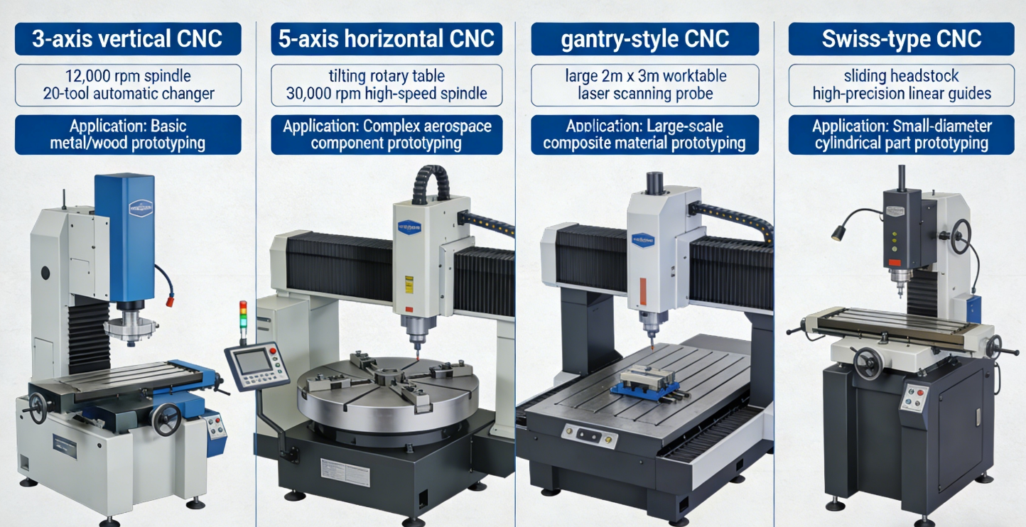
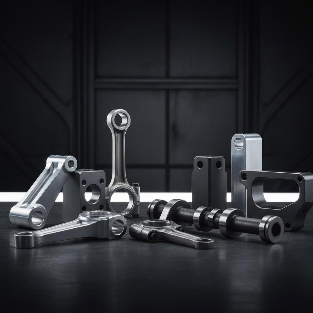
3-Axis CNC Mills represent the workhorse of prototype machining. The cutting tool moves along three linear directions: X (left-right), Y (front-back), and Z (up-down). These machines excel at producing cnc milling parts with straightforward geometries—flat surfaces, pockets, holes, and 2.5D contours. If your prototype only requires machining from one direction, a 3-axis mill delivers excellent results at lower cost. Think mounting brackets, enclosure panels, or simple housings.
4-Axis CNC Mills add rotational capability around the X-axis (called the A-axis), allowing the workpiece to rotate during machining. This configuration shines for cylindrical features, helical patterns, and parts requiring machining on multiple sides without manual repositioning. Cam lobes, specialized shafts, and components with wrap-around features become achievable in fewer setups.
5-Axis CNC Machining Services provide the ultimate in geometric freedom. With simultaneous movement along X, Y, Z axes plus rotation around two additional axes (typically A and B, or A and C), these machines can approach workpieces from virtually any angle. According to industry data from RapidDirect, 5-axis systems achieve tolerances as tight as ±0.0005" with surface roughness values down to Ra 0.4 µm. Aerospace turbine blades, medical implants, and complex automotive components demand this level of capability.
CNC Lathes take a fundamentally different approach—they rotate the workpiece while stationary cutting tools shape the material. This makes them ideal for rotational parts like shafts, bushings, connectors, and any prototype with a cylindrical or conical profile. Modern CNC lathes often include live tooling capabilities, enabling drilling and milling operations on the same machine.
CNC Routers handle larger workpieces and softer materials, making them perfect for wood prototypes, foam patterns, plastic enclosures, and composite panels. While less precise than CNC mills, routers cover bigger work envelopes—sometimes spanning several feet—ideal for signage, architectural models, and large-format prototyping applications.
Matching Machine Capabilities to Prototype Complexity
Choosing the right machine involves balancing several factors. Here's a practical comparison to guide your decision:
| Machine Type | Axis Configuration | Best Prototyping Applications | Complexity Level | Typical Work Envelope |
|---|---|---|---|---|
| 3-Axis CNC Mill | X, Y, Z linear | Flat parts, pockets, 2.5D profiles, mounting plates, simple enclosures | Low to Medium | 12" x 12" x 6" to 40" x 20" x 20" |
| 4-Axis CNC Mill | X, Y, Z + A-axis rotation | Cylindrical features, cam profiles, multi-sided machining, helical cuts | Medium | Similar to 3-axis with rotary table |
| 5-Axis CNC Mill | X, Y, Z + A and B (or C) rotation | Aerospace components, medical implants, turbine blades, complex sculptured surfaces | High | 12" x 12" x 12" to 60" x 40" x 30" |
| CNC Lathe | X, Z (with optional Y, C, live tooling) | Shafts, bushings, fittings, threaded components, rotational symmetry parts | Low to Medium | Up to 24" diameter, 60" length |
| CNC Router | X, Y, Z (3 or 5-axis options) | Large panels, wood patterns, foam prototypes, plastic enclosures, signage | Low to Medium | 48" x 48" to 120" x 60" |
When evaluating your options, consider these practical guidelines:
- Single-side machining with basic features? A 3-axis mill handles most cnc milling components efficiently and cost-effectively
- Parts requiring access to multiple faces? 4-axis or 5-axis cnc machining milling eliminates multiple setups and improves accuracy
- Cylindrical or rotationally symmetric prototypes? CNC lathes with cnc milling turning capabilities deliver optimal results
- Large-format parts in softer materials? CNC routers provide the work envelope you need
- Complex aerospace or medical geometries? 5 axis cnc machining services justify the premium for intricate cnc machine part production
Remember that setup complexity directly impacts lead time and cost. A part requiring three separate setups on a 3-axis machine might complete in a single operation on a 5-axis system—potentially making the more expensive machine economically advantageous for your specific prototype.
Understanding these machine types positions you to make informed decisions about material selection—the next critical factor that determines whether your prototype performs as intended during functional testing.
Material Selection Guide for CNC Prototype Manufacturing
Now that you understand which machine types suit your project, here's the next critical question: what material should you actually cut? Material selection directly impacts how your prototype performs during testing, how efficiently it machines, and whether the final part accurately represents your production intent. Choose wisely, and you'll validate designs faster. Choose poorly, and you'll waste time troubleshooting issues that stem from material mismatch rather than design flaws.
Metal Selection for Functional Prototype Testing
Metals remain the go-to choice when your prototype must withstand real-world mechanical loads, thermal stress, or corrosive environments. Each metal category offers distinct advantages depending on your application requirements.
Aluminum Alloys dominate CNC prototyping for good reason. According to material analysis from RapidDirect, aluminum possesses the highest strength-to-weight ratio among common metals—even surpassing steel in this regard. Milled aluminum parts machine quickly, accept various surface finishes, and resist corrosion naturally through surface oxidation. For automotive and aerospace prototypes demanding lightweight performance, aluminum delivers exceptional results.
- 6061 Aluminum: The most versatile grade with 40 ksi yield strength, excellent corrosion resistance, and outstanding machinability—ideal for structural brackets, heat exchangers, and electronic enclosures
- 7075 Aluminum: With 83 ksi ultimate tensile strength, this aerospace-grade alloy suits high-stress applications like aircraft fittings and machine gears
- 5052 Aluminum: Exceptional saltwater corrosion resistance makes this the preferred choice for marine equipment prototypes
Steel Variants provide superior strength when your metal machining parts must endure demanding structural testing. Stainless steel grades offer excellent wear resistance combined with corrosion protection, making them suitable for medical instruments, food processing equipment, and chemical handling components. Carbon steels deliver higher hardness at lower cost when corrosion isn't a primary concern.
Brass excels in electrical applications and decorative components. This copper-zinc alloy machines beautifully, produces excellent surface finishes, and offers natural antimicrobial properties. When your prototype requires aesthetic appeal alongside electrical conductivity—think connectors, fittings, or instrument housings—brass delivers on both fronts.
Titanium commands premium pricing but justifies the cost for aerospace, medical, and high-performance applications. Its biocompatibility makes it essential for implant prototypes, while exceptional strength-to-weight ratio and heat resistance suit demanding aerospace components. Keep in mind that titanium machines more slowly and requires specialized tooling, increasing both cost and lead time for metal machined prototypes.
Engineering Plastics That Simulate Production Materials
When your prototype needs to validate fit, form, and basic function without the weight or cost of metal, engineering plastics offer compelling alternatives. Modern CNC plastic prototype production handles a wide range of polymers, each with distinct characteristics.
ABS (Acrylonitrile Butadiene Styrene) remains one of the most popular choices for abs cnc machining applications. This thermoplastic delivers high impact resistance, good dimensional stability, and easy machinability at relatively low cost. Consumer product housings, automotive interior components, and electronic enclosures frequently prototype in ABS before transitioning to injection molding.
Polycarbonate steps up when you need optical clarity combined with shatter resistance. Medical device prototypes, automotive lighting lenses, and safety equipment often require polycarbonate's unique combination of transparency and toughness.
PEEK (Polyether Ether Ketone) represents the high-performance end of the plastic spectrum. This advanced polymer handles continuous operating temperatures up to 480°F, resists most chemicals, and provides mechanical properties approaching some metals. Aerospace components, semiconductor equipment, and demanding industrial applications justify PEEK's premium cost.
Delrin (Acetal/POM) offers exceptional stiffness, low friction, and excellent dimensional stability. Gears, bearings, bushings, and precision mechanical components benefit from Delrin's self-lubricating properties and resistance to wear.
For specialty applications requiring extreme temperature resistance, ceramic cnc machining opens additional possibilities. Technical ceramics like alumina and zirconia withstand temperatures exceeding 3000°F while providing electrical insulation and chemical inertness. However, these materials require specialized diamond tooling and careful machining parameters.
| Material Category | Specific Materials | Best Applications | Machining Considerations | Prototype Use Cases |
|---|---|---|---|---|
| Aluminum Alloys | 6061, 7075, 5052, 6063 | Aerospace, automotive, electronics, marine | Excellent machinability, high speeds possible, minimal tool wear | Structural testing, thermal management, lightweight components |
| Steels | 304/316 Stainless, 1018 Carbon, 4140 Alloy | Medical, industrial, structural, high-wear | Moderate to difficult, requires coolant, slower speeds | Load-bearing validation, durability testing, corrosion evaluation |
| Brass | C360 Free-Cutting, C260 Cartridge | Electrical, decorative, plumbing, instruments | Excellent machinability, produces quality finishes easily | Electrical connectors, valve bodies, aesthetic components |
| Titanium | Grade 5 (Ti-6Al-4V), Grade 2 Pure | Aerospace, medical implants, marine, motorsports | Difficult machining, specialized tooling, slow speeds required | Biocompatibility testing, weight-critical applications |
| Engineering Plastics | ABS, Polycarbonate, Nylon, Delrin | Consumer products, automotive interiors, mechanical components | Fast machining, sharp tools required, manage heat buildup | Fit/form validation, functional testing, snap-fit evaluation |
| High-Performance Plastics | PEEK, PTFE, Ultem, PVDF | Aerospace, semiconductor, chemical processing | Moderate difficulty, temperature management critical | High-temp validation, chemical resistance testing |
| Technical Ceramics | Alumina, Zirconia, Silicon Carbide | High-temperature, electrical insulation, wear-resistant | Diamond tooling required, brittle material handling, slow feeds | Extreme environment testing, insulator prototypes |
When selecting materials for machined metal parts or plastic prototypes, always consider the end-use environment. Testing with production-equivalent materials—or close substitutes—ensures your prototype validation translates accurately to final production performance. A material that machines easily but doesn't match your production intent wastes development time and creates false confidence in designs that may fail once manufactured in the correct material.
With your material selected, the next challenge involves designing parts that actually machine successfully. Understanding design-for-manufacturability principles prevents costly surprises when your CAD model meets the machine shop floor.
Design for Manufacturability Principles in CNC Prototyping
You've selected your material and identified the right machine type. But here's where many projects stumble: your beautifully designed CAD model simply won't machine as intended. Sharp internal corners that cutting tools can't reach. Walls so thin they vibrate during cutting. Features buried so deep that no standard tool can access them. These design-for-machining oversights transform straightforward prototypes into expensive headaches requiring multiple redesign cycles.
Understanding DFM principles specific to cnc machining prototype production saves time, reduces costs, and ensures your first physical part actually matches your design intent. According to research from Modus Advanced, effective DFM implementation can reduce manufacturing costs by 15-40% and cut lead times by 25-60% compared to non-optimized designs.
Tolerance Specifications That Ensure Prototype Success
Tolerances define the acceptable deviation between your design dimensions and the finished part. Specify too loose, and your prototype won't function properly during testing. Specify too tight, and you'll pay premium prices for precision that doesn't actually improve performance.
For standard CNC prototyping operations, here's what you can realistically expect:
- ±0.005" (±0.13mm): Standard machining tolerance achievable on most CNC equipment without special procedures—use this as your baseline for non-critical dimensions
- ±0.002" (±0.05mm): Precision tolerance requiring increased attention during machining—adds 25-50% to lead time and should only be specified when functionally necessary
- ±0.0005" (±0.013mm): High-precision work demanding specialized equipment, temperature-controlled environments, and stress relief operations—expect 100-200% longer lead times
- ±0.0002" (±0.005mm): Ultra-precision tolerance requiring extreme environmental controls and specialized inspection equipment—adds 300% or more to manufacturing timelines
The key principle? Apply tight tolerances selectively. Critical mating surfaces, bearing interfaces, and alignment features warrant precision specifications. Decorative surfaces, clearance holes, and non-functional geometry should use standard tolerances. This selective approach keeps prototyping costs manageable while ensuring functional requirements are met.
Wall thickness represents another critical cnc machine design consideration. As noted in Jiga's CNC design guide, thinner walls cost more because they dramatically increase chatter risk, requiring slower feed speeds and shallower cuts to maintain accuracy and acceptable surface finish. For reliable results:
- Metals: Minimum 0.8mm wall thickness as a baseline; 0.5mm possible but increases cost significantly
- Plastics: Minimum 1.2-4mm depending on material rigidity and part geometry
- High-aspect-ratio walls: When height exceeds 4x the wall thickness, expect chatter issues that produce visible milling marks and dimensional inaccuracies
Avoiding Common Design Pitfalls in CNC Prototyping
Certain geometric features consistently cause problems in CNC prototyping. Understanding these limitations before you finalize your design prevents costly surprises when your files reach the machine shop.
Internal Corner Radii
End mills are cylindrical—they physically cannot create sharp 90-degree internal corners. Every internal corner requires a radius matching or exceeding the cutting tool diameter. According to Norck's design guidelines, the recommended radius should be at least 1/3 the depth of the cavity or greater. For cnc milled parts requiring mating components:
- Specify minimum 0.030" (0.76mm) radius for standard internal corners
- Use 0.060" (1.52mm) or larger for deep pockets to allow rigid tooling
- Consider dog-bone or T-bone relief cuts when truly square corners are required for mating parts
- If sharp corners are absolutely essential, secondary EDM operations become necessary—adding significant cost and lead time
Cavity Depth and Width Ratios
Deep, narrow cavities challenge even sophisticated CNC equipment. Tool length limitations, deflection concerns, and chip evacuation problems all intensify as depth increases relative to width:
- Maximum recommended cavity depth: 4x the cavity width
- Feature height should not exceed 4x the feature width
- Holes can reach 30x their diameter in depth—significantly deeper than pockets
- Standard hole diameters range from 1mm to 38mm; smaller holes increase cost substantially
Undercuts and Inaccessible Features
Undercuts—features that standard vertical tooling cannot reach—require special tooling, additional setups, or alternative machining approaches. Before including undercuts in your prototype design:
- Evaluate whether the undercut serves a functional purpose worth the added complexity
- Consider splitting the part into multiple components that assemble together
- Explore 5-axis machining capabilities that can access features from multiple angles
- Budget for 100-200% longer lead times when undercuts are unavoidable
Thread Specifications
Threaded features require careful specification to avoid manufacturing complications. According to industry guidelines:
- Minimum thread sizes: #0-80 (ANSI) or M2 (ISO)
- Recommended thread depth: 3x the nominal diameter for adequate engagement
- Specify thread class and engagement requirements rather than dictating specific drill sizes
- Ensure adequate wall clearance—tapped holes too close to pocket walls risk breakthrough
- Consider through-holes when possible to simplify drilling and tapping operations
3-Axis vs. 5-Axis Design Considerations
Your machine choice fundamentally affects what geometries you can achieve efficiently. Parts designed for 3-axis machining should:
- Align all features with X, Y, and Z planes whenever possible
- Avoid angled surfaces that require multiple setups
- Plan for features accessible from a limited number of orientations
- Accept that some undercuts and complex contours simply aren't practical
5-axis machining unlocks greater geometric freedom but at 300-600% higher cost than 3-axis operations. Reserve 5-axis capabilities for:
- Complex sculptured surfaces requiring continuous tool orientation changes
- Parts with features on multiple angled faces that would require numerous 3-axis setups
- Aerospace and medical components where geometry optimization outweighs cost considerations
- Prototypes where eliminating multiple setups improves accuracy on critical relationships
These DFM principles form the foundation for successful prototype manufacturing. With your design optimized for machinability, the next step involves understanding the complete workflow from CAD file to finished part—ensuring every stage of the process delivers the results you expect.
The Complete CNC Prototyping Workflow from Design to Finished Part
You've designed your part with manufacturability in mind and selected the right material. Now what? Many engineers understand the end goal—a finished prototype in hand—but remain unclear about the exact steps between clicking "export" in CAD software and receiving a precision-machined component. This knowledge gap matters because understanding the complete workflow helps you communicate more effectively with machine shops, anticipate potential delays, and optimize your designs for faster turnaround.
Let's walk through each stage of cnc machining parts production, from digital file preparation to final quality verification. Following this workflow ensures your prototype arrives exactly as specified.
-
CAD File Preparation and Export
Everything begins with your 3D model. Before exporting, verify that your CAD file contains a watertight solid model without gaps, overlapping surfaces, or ambiguous geometry. Check that all dimensions are correctly scaled (millimeters vs. inches creates costly mistakes) and that critical tolerances are clearly annotated.
For CNC prototyping, export your design in one of these preferred formats:
- STEP (.stp/.step): The universal standard for transferring solid geometry between CAD systems—maintains feature accuracy and is widely accepted by machine shops
- IGES (.igs): An older format suitable for simpler geometries; less reliable for complex surfaces
- Parasolid (.x_t): Excellent geometry preservation, commonly used with high-end CAM software
- Native CAD formats: SolidWorks (.sldprt), Inventor (.ipt), or Fusion 360 files work when the machine shop uses compatible software
Include a separate 2D drawing with critical dimensions, tolerances, surface finish requirements, and any special instructions. This drawing serves as the contractual specification for quality testing for cnc machined parts.
-
CAM Programming and Toolpath Generation
Your CAD file doesn't speak the language CNC machines understand. CAM (Computer-Aided Manufacturing) software bridges this gap by translating geometry into precise cutting instructions.
CAD to CAM Translation for Optimal Toolpaths
During CAM programming, a machinist or programmer makes critical decisions that directly impact part quality and production time. According to zone3Dplus's manufacturing workflow analysis, CAM software handles several essential functions:
- Selecting appropriate cutting tools for each feature
- Setting spindle speeds (how fast the tool rotates)
- Defining feed rates (how quickly the tool moves through material)
- Mapping the exact toolpath the cutter will follow
The output is G-code—a numerical control language that tells the machine exactly what movements to execute. Think of G-code as the recipe your CNC machine follows, specifying every single motion down to thousandths of an inch.
Effective toolpath programming balances speed against surface quality. Aggressive cutting parameters reduce cycle time but may leave visible milling marks or cause tool deflection. Conservative parameters produce superior finishes but extend production time. Experienced CAM programmers optimize this balance based on your specific requirements.
-
Machine Setup and Workholding
Before cutting begins, the machine requires careful preparation. This setup phase includes:
- Material Loading: Securing your raw material block (the "workpiece") in a vise, fixture, or clamping system that prevents any movement during machining
- Tool Loading: Installing the required cutting tools in the machine's tool holder or automatic tool changer
- Work Zero Establishment: Precisely locating the machine's coordinate origin relative to your workpiece—this ensures all programmed movements occur in the correct positions
- Tool Length Calibration: Measuring each tool's exact length so the machine compensates correctly during cutting
Workholding decisions significantly impact what features can be machined in a single setup. Parts requiring access to multiple faces may need custom fixtures or multiple setups with careful repositioning between operations.
-
Machining Operations Sequencing
With setup complete, the actual cutting begins. Operations typically follow a logical sequence that progresses from rough material removal to final precision cuts:
- Facing: Establishing a flat reference surface on the top of your workpiece
- Roughing: Rapidly removing bulk material to approximate final geometry, leaving 0.010-0.030" for finishing
- Semi-finishing: Refining surfaces closer to final dimensions while maintaining reasonable cycle times
- Finishing: Final precision passes that achieve specified tolerances and surface quality
- Hole operations: Drilling, boring, reaming, and tapping threaded holes
- Profiling: Cutting external contours and separating the finished part from remaining stock
As noted by MecSoft's CAM programming documentation, understanding cut depth control is extremely important—each operation specifies exactly how deep the tool penetrates relative to your part geometry. For sample machining applications, programmers carefully sequence operations to minimize tool changes and workpiece repositioning.
Throughout machining, coolant floods the cutting zone, serving multiple purposes: preventing heat buildup, lubricating the cut, and flushing away chips that could damage surface finish or cause tool breakage.
-
In-Process Inspection
Critical cnc milled prototypes often require verification during machining—not just after completion. Operators may pause between operations to measure key dimensions, ensuring the part remains within tolerance before proceeding to subsequent cuts. Catching errors mid-process prevents scrapping nearly-complete parts.
-
Part Removal and Cleaning
Once machining completes, the finished cnc machining part requires careful removal from workholding. Operators clean away cutting fluid residue, chips, and debris using compressed air, solvent washes, or ultrasonic cleaning for intricate geometries.
Post-Machining Operations That Complete Your Prototype
Removing your part from the machine doesn't mean it's finished. Most prototypes require additional operations before they're ready for testing or presentation.
Deburring
Machining inevitably creates burrs—small raised edges or metal fragments along cut boundaries. These sharp protrusions affect part function, create safety hazards, and interfere with assembly. Common deburring methods include:
- Hand deburring with specialized tools for accessible edges
- Tumbling or vibratory finishing for batch processing
- Thermal deburring for internal passages and complex geometries
- Electrochemical deburring for precision requirements
Surface Finishing
Depending on your requirements, additional surface treatments enhance appearance, durability, or performance:
- Bead blasting: Creates uniform matte texture and removes machining marks
- Polishing: Achieves mirror-like surfaces for optical or aesthetic applications
- Anodizing: Adds corrosion resistance and color to aluminum prototypes
- Powder coating: Provides durable, colored finishes for functional testing
- Plating: Chrome, nickel, or zinc plating for enhanced wear or corrosion protection
Some applications also require cnc grinding services for ultra-precise surface finishes or tight dimensional control on critical features.
Quality Inspection
Final inspection confirms your prototype meets all specified requirements. Depending on complexity and criticality, inspection may include:
- Dimensional verification: Calipers, micrometers, and height gauges for basic measurements
- CMM (Coordinate Measuring Machine): Automated 3D measurement confirming complex geometry matches CAD specifications
- Surface roughness testing: Profilometers measuring Ra values against your finish requirements
- Visual inspection: Checking for cosmetic defects, burrs, or surface anomalies
- Functional testing: Verifying fit with mating components or performance under simulated operating conditions
Comprehensive quality testing for cnc machined parts documents that your prototype meets specifications before shipping—critical for regulated industries requiring traceability.
Documentation and Delivery
Professional prototyping services provide inspection reports, material certifications, and any required compliance documentation alongside your finished parts. This paperwork becomes essential when transitioning successful prototypes to production manufacturing.
Understanding this complete workflow—from CAD export through final inspection—positions you to make informed decisions about timelines, costs, and quality requirements. But how does CNC prototyping compare to alternative manufacturing methods? The next section breaks down when machining outperforms other approaches and when alternatives might better serve your project needs.
CNC Prototyping Versus Alternative Manufacturing Methods
You understand the CNC prototyping workflow, but here's the real question: is machining actually the right choice for your specific project? With 3D printing advancing rapidly and injection molding offering compelling economics at volume, the answer isn't always straightforward. Making the wrong call wastes budget on an ill-suited process—or worse, delivers prototypes that don't accurately represent your production intent.
Let's build a decision framework that cuts through the noise. By comparing CNC prototyping against alternative methods across key performance criteria, you'll know exactly when machining delivers superior value and when other approaches make more sense.
When CNC Beats 3D Printing for Prototypes
The CNC versus 3D printing debate dominates prototyping discussions, and for good reason—both processes transform digital designs into physical parts. But the similarities end there. According to Jiga's manufacturing analysis, CNC machining achieves tolerances as tight as ±0.01mm, while 3D printing typically ranges from ±0.05mm to ±0.3mm depending on the technology.
Rapid cnc prototyping outperforms additive manufacturing in several critical scenarios:
- Material authenticity matters: CNC machines the exact production materials—6061 aluminum, 316 stainless steel, PEEK—with full isotropic strength. 3D printed parts often exhibit anisotropic properties with reduced strength in certain orientations.
- Surface finish is critical: Machined surfaces achieve Ra 0.4–1.6 µm straight off the machine. 3D printed parts show layer lines ranging from 5–25 µm, typically requiring extensive post-processing for comparable quality.
- Functional testing under load: When your prototype must withstand mechanical stress, thermal cycling, or fatigue testing, CNC delivers parts that behave like production components.
- Tight tolerances are non-negotiable: Precision mating surfaces, bearing interfaces, and assembly-critical features demand CNC's dimensional accuracy.
However, 3D printing wins when your project requires complex internal geometries, lattice structures for lightweighting, or rapid design iterations where material properties aren't the priority. Cnc rapid prototyping and additive methods aren't competitors—they're complementary tools for different challenges.
Volume Thresholds That Determine Your Best Approach
Production quantity fundamentally shifts the economics of prototyping method selection. Understanding these thresholds prevents overspending on small runs or underinvesting when scale justifies different approaches.
For quantities of 1-10 units, rapid prototyping cnc machining and 3D printing compete closely. CNC carries higher setup costs—programming, fixturing, and dry-run verification consume machine time—but delivers production-equivalent parts. 3D printing eliminates setup overhead, making it cost-competitive for very small quantities despite higher per-part material costs.
According to industry cost analysis, the break-even point typically falls somewhere between 5-20 units, heavily influenced by part complexity and material choices. Beyond this threshold, CNC's per-part cost advantage accelerates as setup costs amortize across larger quantities.
Injection molding enters the conversation when quantities exceed 500+ units. The upfront tooling investment—often $5,000 to $50,000+ depending on complexity—makes molding impractical for true prototyping. But when you need hundreds of identical parts for beta testing or market validation, injection molding's low per-unit cost becomes compelling. As noted by Protolabs, injection moulding is ideal for high-volume production and complex geometries with detailed features and material variety.
Manual machining—skilled machinists working with conventional mills and lathes—still serves a purpose for ultra-complex one-off prototypes requiring real-time adaptation. When a part demands constant adjustment, creative problem-solving, or unusual setups that would consume excessive CNC programming time, experienced manual machinists deliver results efficiently. However, this approach doesn't scale and introduces human variability that CNC eliminates.
| Method | Best Volume Range | Material Options | Typical Tolerances | Lead Time | Cost Considerations |
|---|---|---|---|---|---|
| CNC Machining | 1-500+ units | All metals, engineering plastics, composites, ceramics | ±0.01–0.05mm | 1-5 days typical | Moderate setup; decreasing per-part cost at volume |
| 3D Printing (FDM/SLA/SLS) | 1-50 units | Limited polymers, resins; some metals via DMLS | ±0.05–0.3mm | Hours to 3 days | Low setup; high per-part cost at volume |
| Injection Molding | 500-100,000+ units | Wide range of thermoplastics; some thermosets | ±0.05–0.1mm | 2-6 weeks (tooling); days for parts | High tooling investment; very low per-part cost |
| Manual Machining | 1-10 units | All machinable materials | ±0.05–0.1mm (operator dependent) | 1-10 days | High labor cost; no programming overhead |
When evaluating your options, consider these decision criteria:
- Quantity: Under 10 units favors rapid cnc or 3D printing; 50-500 units strongly favors CNC machining rapid prototyping; 500+ units may justify injection molding tooling investment
- Material requirements: Production-equivalent metals or high-performance polymers require CNC; concept models can use 3D printing materials
- Tolerance needs: Features requiring ±0.02mm or tighter demand CNC machining; looser tolerances open alternative options
- Timeline: Same-day needs favor 3D printing; 2-5 day windows suit rapid prototyping cnc; injection molding requires weeks for tooling
- Budget: Limited budgets for small quantities may favor 3D printing; larger budgets with volume requirements benefit from CNC's efficiency
Hybrid workflows increasingly combine these methods strategically. Engineers might 3D print early concepts for form validation, machine functional prototypes in production materials for testing, then transition to injection molding for market launch. According to 3D Actions' prototyping analysis, many developers combine multiple technologies to balance speed, strength, and cost-efficiency effectively.
Understanding these trade-offs positions you to allocate prototyping budget wisely. But another major decision remains: should you invest in in-house CNC capability or partner with external prototyping services? The answer depends on factors beyond simple cost-per-part calculations.
In-House CNC Machines Versus Outsourced Prototyping Services
Now comes the question that can make or break your prototyping budget: should you invest in your own CNC prototyping machine, or partner with a cnc prototyping service? This isn't just a financial calculation—it's a strategic decision affecting your design iteration speed, intellectual property control, and operational flexibility for years to come.
Many teams approach this decision with incomplete data, focusing solely on per-part costs while ignoring hidden expenses that accumulate over time. According to Rivcut's manufacturing analysis, equipment cost represents only about 40% of total in-house investment—operator salaries, facility requirements, and tooling add the remaining 60%. Let's examine when each approach delivers genuine value.
Calculating True Cost of In-House CNC Prototyping
Buying a machine is just the beginning. Your own prototype machine shop generates ongoing costs that must factor into any honest ROI calculation. Based on industry benchmarks, first-year investment for a professional 3-axis setup ranges from $159K-$286K, while 5-axis capability can reach $480K-$1.12M when you account for everything:
- Equipment purchase: $50K-$120K for entry-level 3-axis; $300K-$800K for professional 5-axis systems
- CAM software: $5K-$25K annually depending on complexity and licensing model
- Initial tooling inventory: $10K-$30K for cutters, holders, and workholding
- Operator salary: $60K-$90K annually for qualified machinists
- Training and ramp-up: $5K-$20K plus 12-18 months of reduced productivity
- Facility requirements: $24K-$60K annually for climate control, power, and floor space
- Maintenance and repairs: 8-12% of equipment cost annually
Here's what most teams miss: the learning curve. According to Rivcut's data, new in-house operations experience 40-60% higher material waste and 2-3x longer cycle times during the 12-18 month ramp-up period. This "tuition" often costs $30K-$80K in wasted material and lost productivity that rarely appears in initial ROI projections.
So when does in-house investment actually pay off? Industry data suggests approximately 2,000 machine hours per year represents the break-even threshold—roughly equivalent to single-shift operation at full utilization. Below this level, you're essentially subsidizing expensive equipment that sits idle.
In-house CNC prototyping makes sense when:
- Your volume exceeds 500-800 moderate-complexity parts annually
- High iteration frequency demands same-day turnaround—you're testing, modifying, and re-machining daily
- Proprietary designs require strict IP control with all work on-premises
- You have capital available and can wait 18+ months for full ROI
- Your parts feature simple geometries with relaxed tolerances suited to basic equipment
- You can hire, train, and retain experienced CNC operators in your market
- Facility infrastructure already exists or can be added cost-effectively
As one aerospace prototyping company explained when choosing in-house capability: "Being able to control that feedback loop in-house is very powerful in the early stages of development. Each time we machine a part and hold it in our hands for the first time, we think of 3-4 improvements we want to make." For rapid iteration environments, that tight feedback loop justifies significant investment.
When Outsourcing Delivers Better Value
Online cnc machining services have transformed outsourced prototyping from a slow, unpredictable process into a reliable workflow delivering parts in days rather than weeks. Professional prototype machining services now offer instant quoting, DFM feedback, and lead times as fast as 1-3 days.
Beyond speed, outsourcing eliminates capital risk entirely. You're converting fixed equipment costs into variable per-part expenses that scale with actual demand. For teams searching "cnc milling services near me" or even specialized options like "cnc prototype services georgia," the geographic barriers that once limited outsourcing have largely disappeared through digital quoting platforms and efficient logistics.
Outsourcing wins when:
- Annual volume falls under 300 parts or demand fluctuates unpredictably
- Fast iteration speed is critical but capital preservation matters more than per-part cost
- Parts require complex 5-axis work or specialized capabilities beyond your potential equipment investment
- You prefer focusing internal resources on core engineering rather than machine operation
- You need immediate capacity without the 12-18 month learning curve
- Multiple material types or finishing processes would require diverse equipment investments
- Regulatory compliance requires documented quality systems you'd otherwise need to build from scratch
According to industry cost analysis, for volumes under 300 parts annually, outsourcing typically delivers 40-60% lower total cost when factoring in all hidden expenses. Professional shops also provide DFM support that catches manufacturability issues before they become costly redesigns—expertise that takes years to develop internally.
The Hybrid Approach
Many successful teams combine both strategies, keeping basic prototyping in-house while outsourcing complex or occasional work. This hybrid model provides flexibility without overcommitting capital:
- Maintain entry-level 3-axis capability for rapid iterations on simple parts
- Outsource 5-axis work, exotic materials, and tight-tolerance features to specialists
- Use in-house equipment for design validation; transition to external partners for production-representative prototypes
- Scale external capacity during demand spikes without equipment idle time during slow periods
As noted in manufacturing strategy research, "More and more companies are using a mixed model—keeping basic production in-house and outsourcing more complex or occasional orders to external partners." This balanced approach optimizes both cost and capability.
Whether you build internal capability, partner with external services, or combine both approaches, your decision should align with your specific volume patterns, iteration requirements, and capital constraints. With your sourcing strategy defined, the next consideration involves tailoring your approach to industry-specific requirements—because aerospace, automotive, and medical device prototyping each demand unique considerations beyond general machining principles.
Industry-Specific CNC Prototyping Requirements and Applications
Your sourcing strategy is set, but here's what separates successful prototype programs from costly failures: understanding that prototype machining requirements vary dramatically across industries. A chassis bracket destined for automotive crash testing demands fundamentally different considerations than a surgical instrument heading for clinical trials. Generic prototyping advice falls short when regulatory compliance, material certification, and documentation requirements differ so significantly between sectors.
Let's examine what each major industry actually requires from precision prototyping machining—the specific tolerances, materials, certifications, and documentation that determine whether your prototype validates your design or creates expensive setbacks.
Automotive Prototype Requirements That Ensure Production Viability
Automotive prototyping operates under intense pressure: components must survive rigorous validation testing while meeting cost targets that make mass production viable. According to JC Proto's industry analysis, automotive companies need prototype parts made from production-intent materials to generate valid test data—3D printing simply won't cut it when you're validating crash performance or thermal cycling behavior.
When developing prototype cnc machining programs for automotive applications, consider these category-specific requirements:
Chassis and Structural Components
- Tolerances: ±0.05mm to ±0.1mm for mounting interfaces; ±0.02mm for bearing surfaces and alignment-critical features
- Materials: 6061-T6 and 7075-T6 aluminum for lightweight applications; high-strength steel grades (4140, 4340) for load-bearing prototypes
- Testing requirements: Fatigue testing, crash simulation validation, corrosion resistance verification
- Documentation: Material certifications, dimensional inspection reports, heat treatment records
Powertrain Components
- Tolerances: ±0.01mm to ±0.025mm for rotating components; surface finish Ra 0.4–0.8 µm for sealing surfaces
- Materials: Aluminum alloys for housings; steel and titanium for high-stress rotating parts; specialized alloys for high-temperature exhaust applications
- Testing requirements: Thermal cycling, vibration testing, fluid compatibility verification
- Surface treatments: Anodizing, nickel plating, or thermal barrier coatings depending on operating environment
Interior Elements
- Tolerances: ±0.1mm to ±0.25mm typical; tighter for clip and fastener interfaces
- Materials: ABS, polycarbonate, and glass-filled nylon for functional testing; cnc aluminum prototype parts for structural interior brackets
- Testing requirements: Fit and finish evaluation, haptic feedback validation, UV and temperature stability
- Finish requirements: Production-representative textures for customer clinics and design reviews
For automotive prototype machined parts, quality system certification matters enormously. IATF 16949-certified facilities like Shaoyi Metal Technology provide the quality assurance automotive prototyping demands, with SPC-controlled processes ensuring high-tolerance components for chassis assemblies and precision parts. This certification demonstrates systematic approaches to defect prevention and continuous improvement that automotive OEMs require from their supply chain.
Aerospace Prototyping: Certified Materials and Complete Traceability
Aerospace metal cnc machining operates in a regulatory environment where every material lot, every machining parameter, and every inspection result requires documented traceability. According to Lewei Precision's aerospace capabilities overview, the development cycle progresses through distinct validation phases: engineering validation, design validation, production validation, and finally mass production—each with escalating documentation requirements.
- Material certification: Aerospace prototypes require mill certifications confirming material chemistry and mechanical properties; no substitute materials permitted without engineering approval
- Process documentation: Complete records of cutting parameters, tool selections, and inspection results for every operation
- Tolerances: Typically ±0.01mm to ±0.025mm; surface finishes often specified to Ra 0.8 µm or better
- Preferred materials: Titanium alloys (Ti-6Al-4V), aerospace aluminum (7075-T7351, 2024-T351), Inconel for high-temperature applications
- Quality standards: AS9100 certification for quality management; NADCAP accreditation for special processes like heat treatment or non-destructive testing
- First Article Inspection: Comprehensive dimensional verification against engineering drawings before production approval
The validation sequence matters for aerospace prototyping. Early engineering validation prototypes may use simplified documentation, but design validation and production validation phases require full aerospace-grade traceability. Planning for this documentation burden from project inception prevents costly rework when compliance gaps emerge late in development.
Medical Device Prototyping Compliance Considerations
Medical device cnc prototype machining carries unique responsibilities—these parts may ultimately contact living tissue, deliver medications, or support life-critical functions. According to PTSMAKE's medical manufacturing analysis, medical CNC machining differs primarily in its exceptional precision requirements, biocompatible material selection, strict regulatory compliance, and comprehensive documentation protocols that exceed standard manufacturing practices.
- Biocompatibility requirements: Materials must meet ISO 10993 standards for biological evaluation; common choices include titanium (Ti-6Al-4V), 316L stainless steel, PEEK, and medical-grade polymers
- Precision standards: Tolerances as tight as ±0.0001" (2.54 micrometers) for implantable components; surface finishes of Ra 0.1–0.4 µm for tissue-contacting surfaces
- Sterilization compatibility: Parts must withstand repeated autoclave cycles, gamma radiation, or EtO sterilization without degradation
- Quality system requirements: ISO 13485 certification demonstrates medical-specific quality management; FDA 21 CFR Part 820 compliance for US market access
- Documentation: Complete material traceability, process validation records, and device history files for each production lot
- Cleanroom considerations: Critical components may require manufacturing in ISO 7 or cleaner environments
The regulatory pathway influences prototyping strategy significantly. Clinical trial quantities—perhaps 50 to 500 units—require production-equivalent parts without the massive investment in full production tooling. This is precisely where cnc plastic prototype and metal prototype machining delivers value: functional, biocompatible parts for testing without premature tooling commitment.
As noted in medical manufacturing research, investing in a $100,000 production steel mold before clinical feedback is a huge gamble. Precision prototyping machining allows design iteration based on physician feedback and regulatory input before final production commitment.
Consumer Electronics: Enclosures and Thermal Management
Consumer electronics prototyping balances aesthetic perfection with functional performance—often under aggressive timeline pressure. When a hardware startup completes a successful crowdfunding campaign, they need prototype machined parts that validate both design intent and manufacturing feasibility.
- Enclosure requirements: Tolerances of ±0.05mm to ±0.1mm for snap-fit features and mating surfaces; surface finishes that represent final cosmetic intent
- Materials: 6061 aluminum for metal housings; polycarbonate or ABS for plastic enclosures; magnesium alloys for weight-critical applications
- Thermal management components: Heat sinks requiring tight flatness tolerances (often 0.05mm per 100mm); fin geometries optimized for airflow or passive cooling
- EMI/RFI considerations: Prototype housings must validate electromagnetic shielding effectiveness before production tooling
- Aesthetic requirements: Prototypes often serve dual purposes—functional validation and appearance models for investor presentations or marketing photography
- Rapid iteration: Consumer electronics development cycles demand fast turnaround; lead times of 3-5 days often required for competitive advantage
For startups transitioning from crowdfunding success to market delivery, prototype machining bridges the gap between concept and production. Initial batches of 1,000-5,000 units can be produced through CNC machining while injection molding tools are developed—generating revenue and market feedback simultaneously.
Understanding these industry-specific requirements ensures your prototyping program addresses the right validation criteria from day one. Generic machining services may produce dimensionally accurate parts, but industry-aligned partners understand the documentation, certifications, and quality systems your specific application demands. With these considerations mapped, you're positioned to make smart decisions that accelerate your path from prototype to production.
Making Smart CNC Prototyping Decisions for Your Project
You've covered a lot of ground—machine types, material selection, DFM principles, workflow stages, method comparisons, sourcing strategies, and industry-specific requirements. Now it's time to pull everything together into actionable guidance you can apply immediately, whether you're launching your first cnc prototypes or optimizing an established development program.
The difference between successful prototype programs and costly failures often comes down to making connected decisions rather than isolated ones. Your machine choice affects your material options. Your material selection influences your DFM constraints. Your tolerance requirements determine your sourcing approach. Let's build a framework that ties these elements together.
Your CNC Prototyping Decision Framework
Think of prototyping cnc decisions as a sequence of interconnected choices. Each decision narrows your options for subsequent choices—but also clarifies your path forward. Here's how to approach each stage systematically:
For Beginners Starting Their First Prototype Project:
- Start with function, not features: Define exactly what your prototype must validate—fit testing, functional performance, aesthetic review, or production feasibility. This determines everything else.
- Match materials to your validation goals: If you need production-equivalent performance data, machine the actual production material. If you're testing form and fit only, consider cost-effective alternatives like 6061 aluminum or ABS.
- Apply tolerances selectively: Specify tight tolerances (±0.02mm or better) only where function demands it. Use standard tolerances (±0.1mm) everywhere else to control costs and lead times.
- Leverage DFM feedback: Before finalizing designs, request manufacturability analysis from your machining partner. Catching issues before cutting starts saves significant rework.
- Start with outsourcing: Unless you have clear volume projections exceeding 500+ parts annually, external rapid prototype machining services deliver faster results with lower risk than in-house investment.
For Experienced Engineers Optimizing Workflows:
- Align prototyping with production intent: According to Fictiv's manufacturing experts, selecting prototyping materials that closely match the characteristics of eventual production materials ensures a seamless transition—eliminating material-related surprises at scale.
- Build quality into your design: As manufacturing engineers emphasize, designing for high quality goes beyond DFM or DFA—it ensures that requirements you stipulate can be inspected and achieved consistently throughout production.
- Establish process mapping early: Document your prototype workflow from material acquisition through inspection and shipping. This creates a reference framework for comparing prototype processes against production requirements.
- Evaluate hybrid sourcing models: Maintain basic in-house capability for rapid iterations while outsourcing complex 5-axis work, specialty materials, and high-precision requirements to specialists.
- Partner with certified suppliers: For automotive, aerospace, or medical applications, working with ISO-certified or industry-specific certified facilities (IATF 16949, AS9100, ISO 13485) ensures quality systems align with your compliance requirements from day one.
The most successful CNC prototyping programs treat each prototype as a learning opportunity—not just validating the design, but validating the entire manufacturing pathway from material selection through final inspection.
Scaling from Prototype to Production Successfully
The prototype-to-production transition trips up even experienced teams. According to manufacturing research, one of the hardest things to nail on a product is pricing—get that wrong, and the entire program goes off the rails. Successful scaling requires addressing several factors before committing to volume production:
Design for Assembly (DFA) Considerations:
Your cnc machined prototypes may assemble perfectly by hand, but production assembly introduces different challenges. Frequently, there are issues when transitioning from manually assembling prototypes to automated production lines and robotics. Evaluate whether your design accommodates automated handling, consistent orientation, and repeatable fastening.
Volume-Appropriate Process Selection:
CNC machining remains cost-effective through surprisingly high volumes for certain geometries—but injection molding, die casting, or other processes may deliver better economics beyond 500-1,000 units. Your prototyping partner should help you evaluate when process transitions make financial sense.
Supply Chain Scalability:
Can your prototype supplier scale with you? According to industry analysis, working with a manufacturing partner capable of scaling production up or down—from 1,000 to 100,000 units monthly using the same processes without constraints—can be paramount to success. A rapid cnc machine shop handling 10-unit prototype runs may lack capacity or quality systems for 10,000-unit production.
Quality System Alignment:
Production demands documented, repeatable quality control that prototype quantities may not require. Ensure your production partner maintains certifications appropriate to your industry and can provide the inspection reports, material certifications, and traceability documentation your customers expect.
Partnering with capable manufacturing partners accelerates the entire prototype-to-production journey. Shaoyi Metal Technology exemplifies this approach—scaling seamlessly from rapid prototyping to mass production with lead times as fast as one working day. Their IATF 16949 certification and SPC-controlled processes ensure the quality consistency automotive supply chains demand, making them ideal for teams ready to move beyond prototyping into production-capable manufacturing.
Whether you're machining your first prototype or optimizing an established development workflow, the principles remain consistent: match your decisions to your validation goals, design for manufacturability from the start, select materials that represent production intent, and partner with suppliers whose capabilities align with your scaling trajectory. Apply these principles systematically, and your cnc prototypes become stepping stones to successful products rather than expensive learning experiences.
Frequently Asked Questions About CNC Prototyping Machines
1. How much does a CNC prototype cost?
CNC prototype costs typically range from $100-$1,000+ per part depending on complexity, material selection, tolerances, and finishing requirements. Simple plastic prototypes start around $100-$200, while complex metal parts with tight tolerances can exceed $1,000. Factors like 5-axis machining, exotic materials, and rush lead times increase costs significantly. Working with IATF 16949-certified facilities like Shaoyi Metal Technology can optimize costs through efficient processes while maintaining quality standards for automotive and industrial applications.
2. What is a CNC prototype?
A CNC prototype is a physical part created by combining computer numerical control machining with rapid prototyping principles. The process uses CAD or 3D models to guide precision cutting tools that remove material from solid blocks, producing highly accurate prototypes matching tight specifications. Unlike 3D printing, CNC prototyping uses production-equivalent materials like aluminum, steel, and engineering plastics, delivering parts with authentic mechanical properties ideal for functional testing, fit validation, and design verification before mass production.
3. What is the difference between 3-axis and 5-axis CNC prototyping?
3-axis CNC mills move along three linear directions (X, Y, Z) and excel at flat parts, pockets, and 2.5D profiles with lower cost and simpler programming. 5-axis machines add two rotational axes, enabling tool access from virtually any angle for complex sculptured surfaces, aerospace components, and medical implants. While 5-axis systems achieve tolerances as tight as ±0.0005 inches, they cost 300-600% more than 3-axis operations. Choose 3-axis for straightforward geometries and 5-axis when complex features would require multiple setups otherwise.
4. Should I invest in an in-house CNC machine or outsource prototyping?
The decision depends on annual volume, iteration frequency, and capital availability. In-house CNC makes sense when producing 500+ parts annually, requiring daily design iterations, or protecting proprietary designs. First-year investment for professional setups ranges from $159K-$1.12M including equipment, software, and operators. Outsourcing delivers 40-60% lower total cost for volumes under 300 parts annually, eliminates learning curve losses, and provides immediate access to specialized capabilities. Many teams adopt hybrid models, maintaining basic in-house capability while outsourcing complex work.
5. What materials work best for CNC prototyping?
Material selection depends on your validation goals. Aluminum alloys (6061, 7075) dominate for lightweight automotive and aerospace prototypes with excellent machinability. Stainless steel suits medical instruments and high-wear applications. Engineering plastics like ABS, PEEK, and Delrin work for functional testing of consumer products. For production-equivalent results, always machine the actual production material. Specialty options include titanium for biocompatible implants and technical ceramics for extreme temperature applications, though these require specialized tooling and increase costs.