 Small batches, high standards. Our rapid prototyping service makes validation faster and easier —

CNC Machining Service Decoded: From Material Choice To Final Part
What CNC Machining Service Actually Means for Your Project
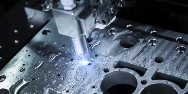
Imagine you have a brilliant design on your computer screen. How does it become a real, physical part you can hold in your hands? That's exactly where a CNC machining service comes in. CNC stands for Computer Numerical Control—a technology that uses pre-programmed software to control the movement of cutting tools with extreme accuracy. Instead of a human operator manually guiding every cut, a computer executes precise instructions, transforming raw blocks of metal or plastic into finished components.
Whether you're a first-time buyer or a seasoned engineer, understanding how this process works helps you make smarter decisions about your projects. Let's break it down step by step.
From Digital Design to Physical Part
The journey from concept to machined parts follows a straightforward workflow. First, you create a 3D model using CAD (Computer-Aided Design) software like SolidWorks, Fusion 360, or Inventor. This digital blueprint captures every dimension, curve, and feature of your component.
Next comes CAM (Computer-Aided Manufacturing) programming. Here, engineers translate your design into toolpaths—the exact routes the cutting tool will follow. The CAM software generates G-code, which is essentially the language CNC machines understand. Think of it as detailed instructions telling the machine where to move, how fast to spin, and how deep to cut.
Finally, the machine executes these commands. Each CNC cut follows the programmed path with remarkable consistency, producing your finished part. According to JLC CNC's manufacturing guide, the typical flow looks like this: CAD Design → Export to CNC-friendly format → Import into CAM software → Create toolpaths → Post-process to G-code → Load into CNC machine → Machining begins.
How Computer Control Revolutionized Manufacturing
Before CNC technology, skilled machinists manually operated every machine. They adjusted dials, cranked handles, and relied on experience to achieve accurate results. While talented operators could produce quality work, human limitations meant inconsistencies between parts and slower production speeds.
CNC machining changed everything. By removing human variability from the cutting process, manufacturers gained the ability to replicate parts flawlessly—whether producing ten units or ten thousand. As noted by Eagle Stainless, CNC machines work continuously without interruptions, handling complex designs much faster than manual methods ever could.
The Core Technology Behind Modern Precision Parts
At the heart of precision CNC machining are several key components working together. The spindle holds and rotates cutting tools at high speeds, while machine axes (typically X, Y, and Z) control movement in three dimensions. More advanced machines add rotational axes for tackling complex geometries.
This technology enables CNC fabrication across countless industries—from aerospace components requiring tight tolerances to medical devices demanding absolute consistency.
So why choose CNC over traditional manual methods? Here are the key advantages:
- Repeatability: Once programmed, a CNC machine produces identical parts every time, ensuring consistent product quality across entire production runs.
- Precision: CNC cuts achieve accuracy levels that are extremely difficult to replicate manually, often holding tolerances within thousandths of an inch.
- Speed: Automated operation means faster cycle times, continuous production, and quicker turnaround for your projects.
- Complexity handling: Intricate designs, tight corners, and detailed features that would challenge manual operators become routine for CNC machines.
- Cost-effectiveness: Reduced labor requirements, minimal waste from errors, and efficient material use translate to long-term savings.
Understanding these fundamentals positions you to make informed decisions throughout your project—from selecting materials to specifying tolerances. The sections ahead will guide you through each critical choice in the machining process.
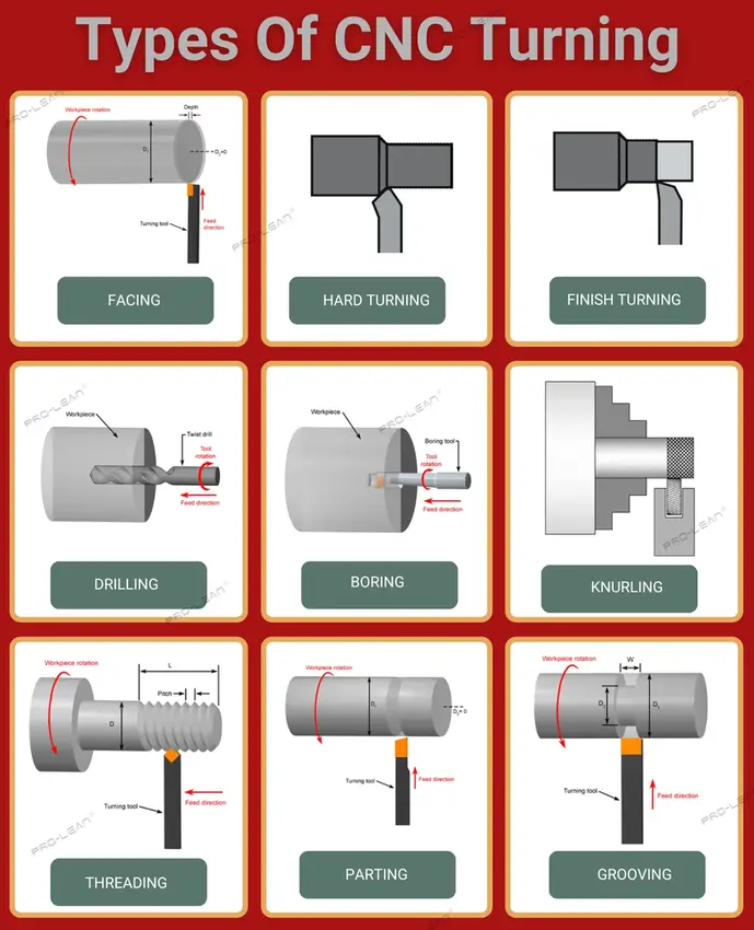
Understanding Different CNC Operations and Their Applications
Now that you understand the basics, here's the next question: which CNC operation is right for your part? Not all machining processes are created equal. Each one excels at specific geometries, materials, and production requirements. Choosing the wrong operation can mean higher costs, longer lead times, or parts that don't meet your specifications.
Let's walk through the major CNC operation types so you can match your project needs with the ideal manufacturing approach.
Milling Operations and When to Use Them
CNC machining milling is one of the most versatile operations available. During milling, a rotating cutting tool moves across a stationary workpiece, removing material to create flat surfaces, slots, pockets, and complex 3D contours. Think of it as sculpting your part from a solid block.
The most common setup is 3-axis milling, where the cutting tool moves along the X, Y, and Z axes. According to Xometry's machining guide, 3-axis machines work best for parts with straightforward geometries and minimal design complexity—things like flat panels, housings, and components with features accessible from one direction. These machines are cost-effective, easy to program, and ideal for startups or small to medium-sized production runs.
When your design demands more, 5 axis CNC machining services step in. These advanced machines add two rotational axes (A and B), allowing the cutting tool to approach the workpiece from virtually any angle. The result? Smoother surfaces, tighter tolerances, and the ability to machine complex contours in a single setup. Aerospace components, turbine blades, and medical implants often require this level of capability. While 5-axis machines cost significantly more—ranging from $80,000 to over $500,000 compared to $25,000-$50,000 for 3-axis equipment—they reduce tool changes and eliminate multiple setups, potentially lowering per-part costs for intricate designs.
Turning for Cylindrical Components
What if your part is round? That's where CNC turning shines. Unlike milling, turning rotates the workpiece while a stationary cutting tool removes material. This makes it the go-to process for shafts, pins, bushings, and any component with a cylindrical profile.
A reliable cnc turning service can produce parts with excellent surface finishes and tight concentricity—critical for components that need to spin smoothly or fit precisely into assemblies. CNC turning parts range from simple cylinders to complex profiles with grooves, threads, and tapered sections.
For even greater precision on small-diameter parts, Swiss machining takes turning to another level. As explained by Vescio Manufacturing, Swiss lathes feed the workpiece through a guide bushing, supporting it extremely close to the cutting point. This minimizes deflection and vibration, enabling the production of long, slender components with exceptional accuracy. Swiss machines can handle bar diameters up to about 32mm and excel at high-volume runs of small, geometrically complex cnc turning parts—think medical fasteners, electronic connectors, and precision pins.
Many cnc turning services offer both conventional and Swiss capabilities, giving you flexibility based on part size and complexity.
Advanced Multi-Axis Capabilities Explained
Beyond standard milling and turning, some projects require specialized processes. EDM (electrical discharge machining) handles situations where conventional CNC cutting struggles. Instead of physical contact between tool and workpiece, EDM uses electrical sparks to erode material.
Why does this matter? According to Fictiv's EDM overview, this process excels at machining hardened steel, exotic alloys, and materials that risk catching fire during traditional milling—like titanium. EDM produces complex geometries without inducing stresses, creates sharp internal corners impossible with rotating cutters, and leaves no burrs. It's commonly used for dies, molds, cooling holes in turbine blades, and surgical instruments.
The trade-off? EDM is slower than conventional machining, making it better suited for prototypes and specialized components rather than high-volume production.
Comparing CNC Operations at a Glance
Choosing the right operation depends on your part's geometry, tolerances, and application. Use this comparison to guide your decision:
| Operation Type | Best Applications | Typical Tolerances | Part Geometry Suited |
|---|---|---|---|
| 3-Axis Milling | Flat surfaces, simple pockets, housings, panels | ±0.005" (±0.127mm) | Prismatic shapes, 2D and 2.5D features |
| 5-Axis Milling | Aerospace parts, impellers, complex contours, molds | ±0.002" (±0.05mm) | Sculptured surfaces, undercuts, multi-sided features |
| CNC Turning | Shafts, bushings, fittings, threaded components | ±0.001" (±0.025mm) | Cylindrical and rotational parts |
| Swiss Turning | Small precision pins, medical fasteners, connectors | ±0.0005" (±0.013mm) | Long, slender cylindrical parts under 32mm diameter |
| EDM | Hardened dies, molds, sharp corners, cooling holes | ±0.0002" (±0.005mm) | Complex internal features, exotic materials |
Understanding these operations helps you communicate effectively with your machining partner and select the process that delivers the best balance of quality, cost, and lead time for your specific project. With the right operation identified, the next critical decision is selecting materials that match your performance requirements.
Selecting the Right Material for CNC Machined Components
You've identified the perfect machining operation for your part. Now comes an equally critical decision: what material should it be made from? This choice affects everything—strength, weight, corrosion resistance, cost, and even the tolerances your CNC machining service can achieve. Yet many buyers approach material selection backward, picking a familiar option without considering whether it truly fits their application.
Let's flip that approach. Instead of listing materials and hoping one matches your needs, we'll start with performance requirements and work toward the ideal choice.
Matching Materials to Performance Requirements
Every machined part exists to serve a purpose. Understanding that purpose guides your material decision. Ask yourself: What forces will this component experience? Will it contact corrosive substances? Does weight matter? Is electrical conductivity important?
For lightweight applications where strength-to-weight ratio matters, aluminum alloys are often the answer. According to Hubs' material selection guide, Aluminum 6061 is the most common general-purpose alloy, offering excellent machinability at low cost. Need aerospace-grade performance? Aluminum 7075 delivers strength comparable to some steels while remaining lightweight.
When corrosion resistance is paramount, stainless steel alloys step in. Stainless steel 304 handles most environmental conditions well, while 316 offers superior resistance to saltwater and harsh chemicals—making it ideal for marine or chemical processing applications.
What about parts that experience constant friction and wear? This is where CNC machining bronze becomes invaluable. Machining bronze creates components like bushings, bearings, and gears that withstand continuous mechanical contact without degrading. As noted by Worthy Hardware's bronze machining guide, bronze CNC parts offer exceptional wear resistance, natural corrosion protection, and excellent machinability—qualities that have kept this material essential for centuries.
For engineering plastics, the choice often comes down to specific environmental factors. Delrin plastic (also called POM) offers the highest machinability among plastics, exceptional dimensional stability, and very low moisture absorption. It's the go-to material when precision and consistency matter. Nylon for machining provides better impact resistance and handles higher temperatures—especially in glass-filled grades that tolerate up to 130°C. CNC polycarbonate delivers outstanding impact strength and optical clarity, making it perfect for protective covers and fluidic devices.
Cost vs Performance Trade-offs in Material Selection
Here's a reality every buyer faces: the ideal material on paper may not be the best choice for your budget. Understanding where you can compromise—and where you can't—separates smart sourcing from costly mistakes.
Consider bronze CNC applications. While aluminum bronze offers incredible strength and saltwater resistance, standard tin bronze may provide adequate performance at lower cost for less demanding applications. The question isn't which material is "better," but which delivers sufficient performance for your specific use case.
According to Penta Precision's material comparison, the raw price difference between Delrin and nylon can range from 10% to 30%. However, Delrin machines faster and cleaner, reducing tool wear and eliminating finishing steps that nylon often requires. For high-precision or high-volume production, Delrin's higher material cost may actually deliver lower per-part pricing.
Material choice also directly impacts achievable tolerances. Rigid materials like Delrin hold tight tolerances effortlessly because they don't deflect during cutting. Flexible materials like nylon can move under tool pressure, making precision more challenging and potentially requiring slower machining speeds.
CNC Machining Materials Comparison
Use this table to quickly identify candidate materials based on your requirements:
| Material | Key Properties | Common Applications | Relative Cost | Machinability Rating |
|---|---|---|---|---|
| Aluminum 6061 | Lightweight, corrosion resistant, excellent thermal conductivity | General-purpose parts, housings, brackets, prototypes | Low | Excellent |
| Aluminum 7075 | High strength, fatigue resistant, heat treatable | Aerospace components, high-stress structural parts | Medium | Good |
| Stainless Steel 304 | Corrosion resistant, weldable, non-magnetic | Food equipment, medical devices, general industrial | Medium | Moderate |
| Stainless Steel 316 | Superior chemical resistance, saltwater tolerant | Marine hardware, chemical processing, pharmaceutical | Medium-High | Moderate |
| Phosphor Bronze | Excellent wear resistance, low friction, fatigue resistant | Bearings, bushings, gears, electrical connectors | Medium-High | Good |
| Aluminum Bronze | High strength, exceptional corrosion resistance | Marine propellers, valves, heavy-duty bearings | High | Good |
| Delrin (POM) | Low friction, dimensionally stable, moisture resistant | Precision gears, valve components, pump parts | Medium | Excellent |
| Nylon 6/6 | Impact resistant, heat tolerant, tough | Wear pads, rollers, structural components | Low-Medium | Good |
| Polycarbonate | Exceptional impact strength, optically clear, tough | Protective covers, optical components, fluidic devices | Medium | Good |
Industry-Specific Material Considerations
Your industry often narrows material choices before you even start. Medical devices frequently require specific grades with documented biocompatibility. Aerospace applications demand materials meeting strict certification standards. Food processing equipment needs FDA-compliant options.
For applications involving continuous sliding contact—think bushings in heavy machinery or bearings in marine equipment—CNC bronze components remain the standard. Bronze's natural lubricity and wear resistance outperform many alternatives in these demanding environments.
When specifying CNC machining materials, remember that surface finish quality ties directly to material properties. Metals like aluminum and bronze polish to mirror finishes easily. Plastics like Delrin machine cleanly with minimal post-processing, while nylon may require additional finishing steps to achieve comparable results.
Armed with material knowledge, your next consideration becomes equally important: designing parts that machines can actually produce efficiently. Understanding design for manufacturability helps you avoid costly revisions and accelerates your project timeline.
Design Principles That Improve Manufacturability and Reduce Cost
You've selected your material and identified the right machining operation. But here's something many buyers overlook: how you design your part often matters more than what it's made from. A well-designed aluminum component can cost less and arrive faster than a poorly designed one in the exact same material. That's the power of Design for Manufacturability—or DFM.
DFM principles help you create CNC machining parts that machines produce efficiently. According to Modus Advanced's engineering guide, effective DFM implementation can reduce manufacturing costs by 15-40% and cut lead times by 25-60% compared to non-optimized designs. Those aren't small numbers—they represent the difference between project success and budget overruns.
Let's explore the specific design choices that separate cost-effective custom machined parts from expensive headaches.
Design Choices That Reduce Manufacturing Cost
Every feature on your part affects how long it takes to machine. Internal corners, pocket depths, wall thicknesses, and hole dimensions all influence tool selection, cycle time, and setup complexity. Understanding these relationships puts you in control of your project costs.
Internal Corner Radii: Here's a fact that surprises many first-time buyers—CNC end mills are round. They physically cannot create sharp 90-degree internal corners. When your design shows sharp corners, machinists must use progressively smaller tools, running multiple passes at slower speeds. According to Hubs' DFM guidelines, specifying a corner radius at least one-third of the cavity depth dramatically reduces machining time. For a 12mm deep pocket, use a 5mm or larger corner radius—this allows standard tooling to work efficiently.
Cavity and Pocket Depth: Deep pockets require long cutting tools that are prone to vibration and deflection. Standard end mills perform best when cavity depth stays within two to three times the tool diameter. Deeper cuts—up to four times diameter—are possible but require slower feeds, specialized tooling, and often increase costs by 50% or more.
Hole Specifications: Standard drill bits cut holes quickly and accurately. Non-standard diameters require additional operations like interpolation or boring, adding time and cost. Specify hole diameters in 0.1mm increments up to 10mm, and 0.5mm increments above that. For depth, limit holes to four times their diameter whenever possible—deeper holes require specialty drills with extended lead times.
Thread Length: Longer threads don't always mean stronger joints. Thread engagement beyond 1.5 times the hole diameter provides little additional strength. Limiting thread length to three times the hole diameter reduces cycle time and avoids the need for special taps.
Avoiding Common Geometry Mistakes
Some design features seem innocent in CAD but create significant manufacturing challenges. Understanding what makes cnc machine parts simple versus complex helps you avoid costly surprises when quotes arrive.
- Overly tight tolerances where unnecessary: Specifying ±0.001" across an entire part when only mating surfaces require it can increase costs by 50-500%. Apply tight tolerances only to functional features.
- Deep pockets with small radii: A 50mm deep pocket with 2mm corner radii requires tiny tools running many passes. The same pocket with 8mm radii machines in a fraction of the time.
- Thin walls prone to deflection: Walls thinner than 0.8mm for metals or 1.5mm for plastics vibrate during cutting, requiring slower speeds and multiple light passes. They also risk cracking or deformation.
- Features requiring special tooling: Decorative curves, complex varying radii, and unusual thread sizes often require custom tools with lead times measured in weeks, not days.
- Knife edges and sharp external corners: Features where two surfaces meet at acute angles create fragile edges that chip during machining and handling. Adding small fillets (0.13-0.38mm) solves this without affecting function.
- Features requiring multiple setups: Blind holes on opposite faces, undercuts, and features at odd angles often require flipping or repositioning the part—each setup adds time and potential tolerance stack-up.
When you're developing a cnc prototype, these geometry choices directly impact how quickly you receive parts for testing. Simpler geometries that follow DFM principles can often be cnc milled in days rather than weeks, accelerating your development cycle.
Optimizing Wall Thickness and Feature Depth
Wall thickness requirements vary by material because different materials respond differently to cutting forces. Use these minimums as guidelines for your cnc milling parts:
| Material Type | Minimum Wall Thickness | Recommended Wall Thickness | Key Consideration |
|---|---|---|---|
| Aluminum Alloys | 0.5mm (0.020") | 0.8mm (0.032") or greater | Reduces vibration, allows faster cutting |
| Steel Alloys | 0.5mm (0.020") | 0.8mm (0.032") or greater | Prevents deflection under tool pressure |
| Stainless Steel | 0.5mm (0.020") | 1.0mm (0.040") or greater | Work hardening requires stable material |
| Engineering Plastics | 1.0mm (0.040") | 1.5mm (0.060") or greater | Prevents melting and deformation |
Feature depth-to-width ratios matter equally. Tall, narrow features act like tuning forks during machining—they vibrate, causing poor surface finish and dimensional inaccuracy. Keep the width-to-height aspect ratio below 4:1 for small features. When taller features are unavoidable, consider adding bracing ribs or connecting them to adjacent walls for stability.
According to MakerVerse's cost reduction guide, understanding these geometric constraints before submitting designs prevents the back-and-forth revisions that delay projects. Manufacturing partners appreciate receiving DFM-optimized files—it signals you understand the process and speeds quote turnaround.
How Part Complexity Affects Your Quote
When a machining service reviews your design, they're mentally cataloging every factor that adds time: How many tool changes? How many setups? Are there features requiring 5-axis work? Will standard tooling work, or do we need specials?
Simple parts share common characteristics: features accessible from one or two directions, standard hole sizes, generous corner radii, and tolerances matching the feature's function. These parts program quickly, machine efficiently, and inspect easily.
Complex parts trigger red flags: features at compound angles requiring 5-axis machining (adding 300-600% to cost), extremely tight tolerances demanding temperature-controlled environments, or decorative curves that serve no functional purpose but require hours of additional programming.
The connection between design and cost is direct. Before finalizing your CAD files, ask yourself: Does every feature serve a purpose? Can any tolerance be relaxed without affecting function? Would splitting this into two simpler parts that assemble together cost less than one complex part?
These questions save money. And once your design is optimized, understanding tolerance specifications becomes the next critical step in ensuring your parts function exactly as intended.
Tolerance Specifications and Their Impact on Your Project
Here's a question that trips up many buyers: what tolerance should you specify? Too loose, and parts won't fit together. Too tight, and costs skyrocket while lead times stretch. Yet most resources simply list tolerance numbers without explaining what they actually mean for your project.
Tolerance defines the acceptable dimensional variation in your machined parts. According to American Micro Industries, no machine delivers the exact same result every time—tolerances establish the controlled margin for error that ensures components function properly within assemblies. Understanding this concept transforms how you approach precision machining services and helps you specify exactly what your application requires.
What Tolerance Levels Mean in Practice
Think of tolerance as a window of acceptable dimensions. A part specified at 25.00mm ±0.10mm can measure anywhere between 24.90mm and 25.10mm and still pass inspection. That's the tolerance band—the complete range of allowable dimensions.
Standard machining tolerances for CNC operations typically fall around ±0.010" (±0.25mm). As noted by Modus Advanced's tolerance guide, this precision level supports the vast majority of engineering applications while maintaining reasonable manufacturing costs and lead times.
Precision machining parts requiring tighter control—±0.005" or better—demand more from the manufacturing process. Precision machining companies achieve these specifications through slower cutting speeds, multiple finishing passes, and more comprehensive inspection protocols. The international standard ISO 2768 establishes tolerance classes ranging from "f" (fine) to "v" (very coarse), providing a common language between designers and manufacturers worldwide.
Here's what matters most: the number of decimal places in your tolerance specification directly correlates with manufacturing difficulty. A tolerance of ±0.02" permits a range ten times wider than ±0.002". That difference dramatically affects production complexity, machine selection, and ultimately your project cost.
Tolerance Classes and Their Applications
Selecting the right tolerance class starts with understanding your part's function. Use this reference to match precision requirements with real-world applications:
| Tolerance Class | Typical Range | Application Examples | Cost Impact | When Required |
|---|---|---|---|---|
| Standard | ±0.010" (±0.25mm) | Housings, brackets, covers, general structural components | Baseline | Non-mating surfaces, cosmetic features, general clearance holes |
| Close | ±0.005" (±0.13mm) | Sliding fits, locating features, precision assemblies | +25-50% | Parts requiring consistent fit with some movement allowance |
| Precision | ±0.002" (±0.05mm) | Press fits, bearing seats, critical alignment features | +100-200% | Interference fits, high-precision assemblies, aerospace components |
| Ultra-Precision | ±0.0005" (±0.013mm) | Medical implants, optical components, semiconductor equipment | +300-500% | Life-critical applications, optical surfaces, extreme environments |
Connecting Precision Requirements to Applications
Different features on the same part often need different tolerances. Understanding fit types helps you specify appropriately:
Clearance holes: These need to be larger than the fastener passing through them. Standard tolerances work perfectly—a clearance hole for an M6 bolt might be specified at 6.5mm ±0.25mm. The extra room accommodates assembly without affecting function.
Sliding fits: Components that move against each other—like pistons in cylinders or drawers in housings—need tighter control. Too loose and they wobble; too tight and they bind. Close tolerances around ±0.005" typically achieve the right balance.
Press fits: When parts must stay permanently joined through interference—a bearing pressed into a housing, for example—precision tolerances become essential. The interference must be consistent enough to hold under operating conditions without cracking the surrounding material.
Cosmetic surfaces: Visible surfaces often prioritize surface finish over dimensional precision. Standard tolerances usually suffice, while surface roughness specifications (Ra values) control the visual and tactile quality.
A precision machining service evaluates your tolerance callouts to determine machine selection, cutting strategies, and inspection requirements. Parts specified within standard tolerances flow through production efficiently. Precision machining parts trigger additional operations—slower feeds, lighter cuts, and CMM verification—that extend timelines and increase costs.
The Real Cost of Tighter Tolerances
Why do tighter tolerances cost more? The answer involves every stage of manufacturing:
Machine selection: Standard tolerances can be achieved on a wide range of equipment. Precision tolerances often require newer machines with higher accuracy, better thermal stability, and more rigid construction—equipment that costs more to acquire and operate.
Cycle time: Achieving ±0.002" instead of ±0.010" typically requires slower spindle speeds, lighter depth of cut, and additional finishing passes. What might take 10 minutes at standard tolerance could take 25-40 minutes at precision levels.
Tool wear: Precision work demands sharper tools and more frequent replacements. Worn tools that would perform acceptably for standard work produce out-of-tolerance precision machining parts.
Inspection requirements: Standard parts might receive spot-check verification. Precision parts often require 100% CMM inspection, first article inspection reports, and statistical process control documentation. According to American Micro Industries, parts exceeding tolerance limits become unusable in most applications—so verification intensity scales with tolerance tightness.
Environmental control: Ultra-precision work may require temperature-controlled environments because thermal expansion affects measurements at these scales. A 10°C temperature swing can move aluminum dimensions by 0.0002" per inch.
The key insight: specify tight tolerances only where function demands them. A part with twenty dimensions doesn't need twenty tight tolerances—typically only two or three features actually require precision control.
Before submitting your design, review every tolerance callout and ask: what happens if this dimension varies by ±0.010" instead of ±0.002"? If the answer is "nothing functional changes," relax that tolerance and save money where it doesn't compromise performance.
With tolerances properly specified, your next consideration becomes equally important: understanding how CNC machining compares to alternative manufacturing methods—and when each approach makes the most sense for your project.
CNC Machining Compared to Alternative Manufacturing Methods
You've learned how CNC machining works, which operations suit your parts, and how to optimize designs for manufacturability. But here's a question worth asking: is CNC even the right choice for your project? Sometimes it absolutely is. Other times, alternative manufacturing methods deliver better results at lower costs.
Understanding when CNC excels—and when it doesn't—helps you make smarter sourcing decisions. Let's compare the major manufacturing processes honestly, including where CNC falls short.
When CNC Outperforms Other Manufacturing Methods
CNC machining dominates certain manufacturing scenarios. According to Formlabs' manufacturing guide, CNC tools are ideal for producing custom or low-volume end-use parts, structural components, and tooling across a wide range of industries. Here's where metal machining and CNC prototyping truly shine:
Low-to-medium volume production: When you need anywhere from one to several thousand parts, CNC delivers without the tooling investments that injection molding or die casting require. There's no $10,000+ mold to amortize—you're paying primarily for machine time and material.
Tight tolerance requirements: CNC machines consistently achieve tolerances of ±0.05mm or better, with high-precision operations reaching ±0.0002 inches. As noted in TriMech's prototyping comparison, this level of dimensional accuracy is extremely difficult to replicate with additive processes, where typical tolerances range from ±0.05 to ±0.1mm.
Metal cnc machining applications: When your application demands the mechanical properties of wrought metals—consistent grain structure, predictable strength, and fatigue resistance—CNC machining delivers. Aluminum machining, steel milling, and cnc aluminum parts retain the full structural integrity of their base materials. Unlike 3D printed metals that may require post-processing to achieve comparable properties, CNC machined parts come off the machine ready for service.
Material versatility: CNC machines work with virtually any machinable material—metals, plastics, composites, and even wood. Need a prototype in the exact production material? CNC plastic machining produces parts identical to injection-molded versions, making functional testing more reliable.
Surface finish quality: Machined surfaces typically measure Ra 1.6-3.2 μm directly off the machine, with polishing achieving mirror finishes below Ra 0.4 μm. Additive manufacturing parts require significant post-processing to approach these results.
Situations Where Alternatives Make More Sense
Honest assessment matters here. CNC machining isn't always the best choice, and recognizing its limitations saves money and time.
Very high volumes: Once quantities exceed 10,000+ identical parts, injection molding's economics become compelling. Yes, the mold costs $10,000-$100,000+, but per-part costs drop to pennies. At 100,000 units, that mold investment becomes trivial per piece. CNC's per-part cost remains relatively flat regardless of volume.
Complex internal geometries: Internal lattices, cooling channels with curved paths, and organic shapes often prove impossible to machine. According to TriMech's analysis, features like honeycomb structures and entire assemblies built in a single job are "effortlessly handled by 3D printing, as the layer-by-layer process removes many traditional manufacturing constraints." CNC cutting tools physically cannot reach these geometries.
Material waste concerns: CNC is subtractive—you start with a solid block and remove everything that isn't your part. For complex geometries, 50-90% of the starting material can end up as chips. Formlabs notes that "to make 8 kg of parts via machining, you might need 50-100 kg of raw material." When machining expensive alloys like titanium or Inconel, this waste significantly impacts costs.
Extremely complex prototypes for iteration: When you're still exploring design possibilities and need to test organic shapes, 3D printing's design freedom accelerates iteration. You can print, test, and modify without worrying about machining constraints. Once the design stabilizes, CNC prototyping produces functional parts in production materials.
Thin-walled or sheet-based parts: Sheet metal fabrication produces enclosures, brackets, and panels more efficiently than machining from solid blocks. Why waste material cutting away 90% of a billet when bending sheet stock achieves the same geometry?
Manufacturing Methods Comparison
This table provides a direct comparison to guide your process selection:
| Process | Best Volume Range | Material Options | Typical Tolerances | Lead Time | Per-Unit Cost Trend |
|---|---|---|---|---|---|
| CNC Machining | 1-10,000 parts | Metals, plastics, composites—virtually unlimited | ±0.025-0.125mm | Days to weeks | Relatively flat across volumes |
| 3D Printing (Metal) | 1-500 parts | Limited to printable alloys (Ti, Al, SS, Inconel) | ±0.05-0.1mm | Days to weeks | Higher per-part, decreases slightly with nesting |
| 3D Printing (Plastic) | 1-1,000 parts | Engineering resins, nylons, TPU | ±0.1-0.3mm | Hours to days | Moderate, decreases with batch builds |
| Injection Molding | 10,000+ parts | Thermoplastics, some thermosets | ±0.05-0.1mm | Weeks to months (tooling) | Very low at high volumes |
| Die Casting | 5,000+ parts | Aluminum, zinc, magnesium alloys | ±0.1-0.5mm | Weeks to months (tooling) | Low at high volumes |
| Sheet Metal Fabrication | 1-50,000 parts | Sheet metals (steel, aluminum, stainless) | ±0.1-0.5mm | Days to weeks | Low for appropriate geometries |
Combining Processes for Optimal Results
Here's what experienced manufacturers know: the best solution often combines multiple processes. Rather than choosing one method exclusively, consider how they complement each other.
3D print then machine: Many metal 3D printed parts undergo post-machining to achieve tighter tolerances and better surface finishes on critical features. According to TriMech's analysis, this hybrid approach captures the geometric freedom of additive manufacturing while delivering the precision of aluminum cnc or steel machining where it matters most.
Prototype with CNC, produce with molding: CNC prototyping validates your design in production-equivalent materials before committing to expensive injection mold tooling. Once verified, you transition to high-volume molding with confidence.
Cast then machine: Die castings provide near-net-shape parts at high volumes, with CNC finishing critical surfaces, threads, and tight-tolerance features. The casting handles bulk geometry efficiently; machining adds precision where needed.
Print tooling for CNC: 3D printed fixtures and jigs reduce setup time for CNC machining operations. The printed tooling holds parts consistently, enabling faster changeovers between production runs.
Pros and Cons: CNC vs. 3D Printing for Metal Prototypes
CNC Machining Pros
- Superior dimensional accuracy (±0.01mm achievable)
- Consistent mechanical properties matching wrought materials
- Excellent surface finish directly off the machine
- Broad material selection including common alloys
- Cost-effective for larger parts with simple geometries
CNC Machining Cons
- Significant material waste (up to 50-90% for complex parts)
- Cannot produce internal channels or lattice structures
- Setup time adds cost for one-off parts
- Geometric limitations based on tool access
Metal 3D Printing Pros
- Complex geometries including internal features and lattices
- Near 1:1 material efficiency (minimal waste)
- No tooling or setup for new designs
- Often 10-20% stronger than wrought equivalents in titanium and aluminum alloys
Metal 3D Printing Cons
- Lower dimensional accuracy (±0.05-0.1mm typical)
- Rougher surface finish requiring post-processing
- Limited to printable alloy powders (more expensive than bar stock)
- Build volume constraints for larger parts
The manufacturing method that serves you best depends on your specific requirements: volume, geometry, material, tolerance, and timeline. CNC metal machining remains the workhorse for precision components in low-to-medium volumes—but knowing when alternatives deliver better value makes you a smarter buyer.
Once you've selected the right manufacturing approach, understanding how quality assurance processes verify your parts becomes essential. Certifications and inspection methods ensure the components you receive actually meet your specifications.
Quality Assurance Processes and Industry Certifications Explained
You've designed your part, selected materials, and chosen the right manufacturing method. But here's a critical question many buyers overlook: how do you know the parts you receive actually meet your specifications? Certifications and quality logos appear on nearly every machining provider's website—yet few explain what these credentials actually mean for your components.
Understanding quality assurance transforms you from a passive buyer into an informed partner. Let's demystify what happens behind the scenes at precision cnc machining services and why certifications matter for your specific applications.
What Happens During Quality Inspection
Quality inspection isn't a single checkpoint—it's a series of verifications occurring throughout production. According to American Micro Industries, certified processes mean the methods and equipment themselves are held to documented standards, promoting consistency from one batch to the next.
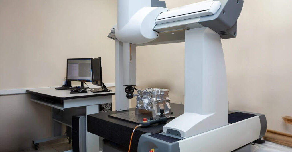
First Article Inspection (FAI): Before full production begins, the first completed part undergoes comprehensive measurement against every dimension on your drawing. As noted by ZEISS Metrology, first article inspection often operates under time pressure—the manufacturing team needs quick feedback to confirm the setup is correct before committing to a full production run. This inspection typically includes complete dimensional verification, material certification review, and surface finish measurement.
CMM Measurement: Coordinate Measuring Machines use precision probes to capture exact dimensions at hundreds or thousands of points across your part. Modern CMMs compare these measurements directly against your CAD model, identifying deviations down to microns. For cnc precision machining services producing aerospace cnc machining components, CMM verification often occurs on 100% of critical features rather than statistical sampling.
Surface Finish Testing: Profilometers measure surface roughness (Ra values) to verify parts meet visual and functional requirements. Medical machining applications often specify extremely smooth surfaces to prevent bacterial growth, making this verification essential.
Material Certification Verification: Every batch of raw material arrives with mill certificates documenting its chemical composition and mechanical properties. Quality teams verify these certificates match your specifications before machining begins—because even perfect machining can't fix wrong material.
Understanding Industry Certifications
Certifications signal that a manufacturer has implemented—and regularly demonstrates—systematic quality controls. But different certifications serve different industries. Here's what each one actually means:
ISO 9001: This internationally recognized standard establishes baseline quality management systems. According to American Micro Industries, core principles include customer focus, process approach, continual improvement, and evidence-based decision-making. An ISO 9001 certified shop documents workflows, monitors performance metrics, and addresses nonconformities with corrective action. Think of it as the foundation that all other certifications build upon.
AS9100D: This aerospace-specific certification builds on ISO 9001 with additional requirements for risk management, stringent documentation, and product integrity control throughout complex supply chains. Aerospace cnc machining facilities holding AS9100D have demonstrated capability to meet the demanding expectations of aviation and defense customers. If your parts fly, this certification matters.
IATF 16949: The global standard for automotive quality management combines ISO 9001 principles with sector-specific requirements for continuous improvement, defect prevention, and stringent supplier oversight. Custom cnc machining services serving automotive OEMs typically require this certification. Facilities like Shaoyi Metal Technology maintain IATF 16949 certification specifically to serve automotive applications requiring consistent quality for chassis assemblies and precision components.
ISO 13485: Medical machining demands this specialized certification covering design controls, traceability, and risk mitigation specific to medical devices. Facilities seeking ISO 13485 must implement detailed documentation practices and thorough quality checks ensuring every component is safe, reliable, and fully traceable.
NADCAP: Unlike general quality certifications, the National Aerospace and Defense Contractors Accreditation Program focuses specifically on special processes—heat treating, chemical processing, and nondestructive testing. This accreditation validates that a manufacturer can consistently perform specialized processes at the highest standard.
Documentation and Traceability Requirements
Certifications translate into tangible documentation that travels with your parts. When you receive components from precision machining services, expect these records:
- Inspection Reports: Detailed dimensional measurements comparing actual values against specifications, typically including pass/fail status for each characteristic
- Material Certificates: Mill test reports documenting the chemical composition, heat treatment, and mechanical properties of raw materials used
- Dimensional Reports: CMM output showing measured values, deviations from nominal, and conformance to tolerance bands
- Certificates of Conformance: Formal statements that parts meet all drawing requirements and applicable specifications
- First Article Inspection Reports: Comprehensive documentation from initial production verification, often required for stainless steel machining in regulated industries
- Process Control Records: Evidence of in-process checks, tool changes, and any deviations addressed during production
Statistical Process Control and Consistency
For production runs beyond prototypes, Statistical Process Control (SPC) ensures consistency across every part—not just the ones inspected. SPC monitors key dimensions continuously, using statistical methods to detect process drift before it produces out-of-tolerance parts.
Here's how it works: operators measure critical dimensions at regular intervals and plot results on control charts. As long as measurements stay within control limits, the process is stable. When a trend appears—even if parts still pass inspection—SPC flags the issue for correction before defects occur.
According to American Micro Industries, certified professionals and processes reduce defects, rework, and material waste because everyone operates under uniform practices with clear expectations. Facilities implementing rigorous SPC—like Shaoyi Metal Technology for automotive machining parts—demonstrate the discipline required to deliver consistent quality across thousands of components.
Matching Certifications to Your Requirements
Not every project requires every certification. Here's a practical guide:
| Your Industry | Required Certification | Why It Matters |
|---|---|---|
| General Industrial | ISO 9001 | Ensures documented quality processes and continuous improvement |
| Aerospace/Aviation | AS9100D, potentially NADCAP | Mandatory for flight-critical components; validates traceability and risk management |
| Automotive | IATF 16949 | Required by major OEMs; demonstrates defect prevention and supplier oversight |
| Medical Devices | ISO 13485 | Ensures compliance with FDA requirements and patient safety standards |
| Defense | AS9100D, ITAR registration | Controls sensitive data handling alongside quality management |
When evaluating precision machining companies, ask specifically about certifications relevant to your application. A shop holding AS9100D has invested significantly in quality infrastructure—that investment translates to actual part quality, not just a logo on their website.
Quality verification gives you confidence that parts meet specifications. But there's another critical factor affecting your project success: understanding how volume, lead time, and cost interact—and how to optimize all three for your specific needs.
Managing Lead Times and Understanding Volume Pricing
You've verified quality processes and understand what certifications mean. Now comes a question that directly impacts your budget and schedule: how do volume, lead time, and cost actually relate to each other? Many buyers receive quotes without understanding why prototype machining costs $150 per part while the same component drops to $8 each at 1,000 units. This relationship isn't arbitrary—it follows predictable patterns you can leverage.
Understanding these dynamics transforms you from someone who simply accepts quotes into someone who optimizes projects strategically. Let's decode the economics of CNC machining prototyping and production.
How Volume Affects Per-Unit Pricing
Every CNC project carries fixed costs that exist regardless of whether you order one part or one thousand. According to RapidDirect's cost analysis, the total cost formula breaks down as: Total Cost = Material Cost + (Machining Time × Machine Rate) + Setup Cost + Finishing Cost. Understanding each component explains why unit prices behave the way they do.
Setup costs dominate low-volume orders. Before any cutting begins, engineers must program toolpaths, create fixtures, set up tools, and run test cuts. This investment might total $200-$500 for a moderately complex part. Order one piece, and that entire setup cost lands on your single unit. Order 100 pieces, and each part carries only $2-$5 of setup burden.
RapidDirect's data illustrates this dramatically:
| Quantity | Approximate Unit Price | Setup Cost Per Unit |
|---|---|---|
| 1 part | $150 | $100+ (setup dominates) |
| 10 parts | $35 | $10 |
| 100 parts | $12 | $1 |
| 1,000 parts | $8 | $0.10 |
Material purchasing efficiencies emerge at volume. Buying 50 feet of aluminum bar stock costs less per foot than buying 6 inches. Suppliers offer quantity breaks, and material waste percentages improve when nesting multiple parts from common stock sizes.
Programming time distributes across runs. CAM programming might take 4-8 hours for a complex part. That investment applies whether you make 5 parts or 500. Larger batches also justify optimization—spending extra programming time to shave 30 seconds per cycle pays off when multiplied across hundreds of units.
However, RapidDirect notes that extremely high quantities don't always guarantee the lowest price. Capacity constraints, machine allocation, and finishing bottlenecks may limit volume efficiency. The ideal price point often appears at low-to-medium production volumes (50-500 pieces), where setup cost is distributed efficiently without overwhelming the machining workflow.
Factors That Determine Production Timeline
When you need a cnc quote online, lead time estimates depend on far more than just machining hours. According to JLC CNC's manufacturing guide, multiple factors combine to determine your actual delivery date.
Design complexity sets baseline machining time. Complex parts requiring multiple setups, extensive tool changes, or 5-axis operations inherently take longer than simple geometries. A straightforward bracket might machine in 15 minutes; a complex housing with features on all six faces might require 4 hours of machine time plus multiple setups.
Material procurement can add days or weeks. Common materials like 6061 aluminum and 304 stainless steel sit on shelves at most shops. Exotic alloys, specific heat treatments, or unusual stock sizes may require ordering—potentially adding 1-3 weeks before machining even begins. JLC CNC recommends working with reliable suppliers and considering material flexibility when timelines are critical.
Machine availability varies with shop loading. A facility running at 90% capacity schedules your job differently than one at 60% utilization. Rush orders compete with existing commitments. Building relationships with manufacturers helps you understand their typical loading and plan accordingly.
Secondary operations extend timelines significantly. According to Spex Manufacturing, secondary processes form features that weren't done in initial machining—deburring, engraving, sub-assembly, and surface treatments like anodizing, heat treatment, and powder coating. Each adds processing time:
- Heat treatment: Stress relieving, hardening, or tempering typically adds 3-7 days depending on batch scheduling
- Anodizing: Usually 3-5 days for standard finishes; longer for hard anodize or special colors
- Plating (zinc, nickel, chrome): 5-10 days including preparation and curing
- Powder coating: 3-5 days for standard colors; custom matches add time
- Assembly: Variable based on complexity; may require additional fixtures or specialized labor
Spex notes that "the more complex or specific the secondary process, the longer it might take. A simple deburring process might add minimal time, while multi-step surface treatments could extend the lead time significantly."
Inspection requirements scale with tolerance tightness. Standard parts receive spot-check verification. Precision parts demanding full CMM inspection of every critical feature add measurement time. First article inspection for new production runs requires comprehensive documentation before releasing full batches.
Strategies to Optimize Turnaround and Cost
You're not powerless against lead times and costs. Strategic decisions during design and planning phases dramatically affect both. Here's how experienced buyers optimize their projects:
- Optimize designs for manufacturability: Simplify geometry, increase corner radii, and avoid features requiring special tooling. RapidDirect notes that up to 80% of manufacturing cost is locked in during the design phase—changes here have the biggest impact.
- Build material flexibility into specifications: If 7075-T6 aluminum works but 6061-T6 is acceptable, specify both options. The shop may have 6061 in stock while 7075 requires ordering.
- Relax tolerances where function permits: Tight tolerances increase inspection time, require slower machining, and may trigger additional quality documentation. Specify precision only where it matters.
- Plan ahead for secondary operations: If your parts need anodizing, build that week into your schedule from the start. Discovering finishing requirements after machining completes creates avoidable delays.
- Batch similar parts together: If you have multiple part numbers using the same material and similar tolerances, quoting them together may enable setup efficiencies.
- Use prototype machining services strategically: Rapid cnc prototyping validates designs quickly, but don't expect production pricing. Use prototypes to confirm fit and function, then optimize designs before committing to larger volumes.
- Communicate timeline requirements upfront: Shops can often accommodate urgent needs if they know about them during quoting—not after order placement.
Scaling from Prototype to Production
The transition from cnc prototype machining to full production often surprises buyers. Prototype pricing reflects one-time setup, first-article verification, and potentially non-optimized toolpaths. Production pricing assumes refined processes, proven fixtures, and predictable cycle times.
When requesting online machining quotes, ask how pricing changes across quantity breaks. Understanding the cost curve helps you make smart decisions about order sizing. Sometimes ordering 150 parts costs only marginally more than 100—but delivers significant per-unit savings and spare inventory.
Facilities offering comprehensive prototype machining services through production scaling—like Shaoyi Metal Technology with lead times as fast as one working day for automotive components—demonstrate the timeline flexibility available when you partner with capable manufacturers. Their ability to scale from rapid prototyping to mass production for chassis assemblies and precision components illustrates how established providers compress timelines without sacrificing quality.
Planning for scale during prototype development pays dividends. Designs that machine efficiently at one-off quantities also machine efficiently at volume—but designs optimized only for prototyping may require costly revisions before production.
The key insight: lead time and cost aren't fixed constraints—they're variables you influence through design decisions, material choices, tolerance specifications, and planning.
Armed with understanding of volume economics and timeline factors, you're ready to evaluate potential manufacturing partners. Selecting the right CNC machining provider brings all these elements together into successful project execution.
Choosing the Right CNC Machining Partner for Your Needs
You've learned how CNC machining works, which materials and tolerances suit your application, and how volume affects pricing. Now comes the decision that brings everything together: selecting the right manufacturing partner. This choice determines whether your project runs smoothly or becomes a frustrating experience of delays, miscommunication, and parts that don't meet specifications.
Finding a reliable custom machine shop isn't about picking the lowest quote. It's about matching capabilities to requirements—and building a relationship that supports both your current project and future needs.
Evaluating CNC Service Providers Effectively
When you search for cnc machine shops near me or machining shops near me, dozens of options appear. How do you separate capable partners from those who'll struggle with your requirements? According to 3ERP's evaluation guide, experience equates to expertise—but don't just look at years of operation. Consider the projects a particular shop has worked on and the types of clients it has served.
Start with certifications relevant to your industry. As covered earlier, automotive projects require IATF 16949 certification. Aerospace applications demand AS9100D. Medical components need ISO 13485. A shop displaying ISO 9001 demonstrates baseline quality management—but specialized applications require specialized credentials. Don't assume certifications; verify them.
Material capabilities matter more than you might expect. Not every local machine shop stocks the material you need. According to 3ERP, delays in sourcing materials can lead to extended lead times and increased production costs. Ask specifically: do they have your material in stock? Can they source it readily? What's their typical lead time for specialty alloys?
Tolerance capabilities should match your specifications. A shop running older equipment may struggle with the ±0.002" tolerances your design requires. Ask about their standard tolerances and what precision levels they achieve regularly—not occasionally. Request examples of similar work.
Communication responsiveness signals overall service quality. 3ERP emphasizes that an effective communication process means the service provider can promptly address your queries, update you on progress, and quickly rectify any issues. During the quoting process, note how quickly they respond and how thoroughly they answer questions. This behavior predicts their performance during production.
Quality documentation should be comprehensive and automatic. A capable custom machine understands that inspection reports, material certificates, and certificates of conformance aren't optional extras—they're standard deliverables. Ask what documentation accompanies shipments and whether first article inspection is available.
Preparing Your Project for Success
Even the best machinist shops near me can't rescue poorly prepared projects. According to Dipec's preparation guide, the way you prepare and submit your design files can make all the difference in achieving the desired result. Well-prepared files lead to better outcomes, fewer delays, and optimal material usage.
Before requesting quotes, complete this preparation checklist:
- Finalize CAD files in standard formats: STEP (.step/.stp) and IGES (.iges/.igs) files are industry standards that most CAM software reads reliably. Always accompany your primary CAD file with a technical drawing in PDF format, especially when you have critical tolerances or surface finish requirements.
- Specify critical tolerances clearly: Mark which dimensions require tight control and which can accept standard tolerances. Include GD&T callouts where appropriate. Remember—every tight tolerance increases cost, so apply precision only where function demands it.
- Identify material requirements completely: Specify alloy grade, temper condition, and any material certifications required. If alternatives are acceptable, note them—this gives the shop flexibility to use in-stock materials.
- Determine quantity needs realistically: Include both immediate requirements and anticipated future volumes. Many shops offer better pricing when they understand the full production picture.
- Establish timeline expectations upfront: Communicate your need date during quoting, not after order placement. Shops can often accommodate urgent needs if they plan for them from the start.
- Define secondary operation requirements: Heat treatment, anodizing, plating, or assembly all affect lead time and cost. Include these requirements in your initial request to receive accurate quotes.
Dipec notes that submitting a file with missing information—such as dimensions, materials, or units—can lead to delays, incorrect parts, or even job rejections. A well-prepared file improves turnaround time, accuracy, and overall machining efficiency.
Interpreting Quotes and Asking the Right Questions
When quotes arrive, resist the urge to simply compare bottom-line prices. According to Longsheng Manufacturing's quote evaluation guide, evaluating a CNC machining quote is a systematic process that requires comprehensive consideration of a variety of key factors—not just a simple comparison of prices.
Look beyond unit pricing to understand what's included. Does the quote cover inspection? Material certification? Packaging appropriate for your parts? Are there setup charges listed separately or buried in unit costs? Understanding the quotation's composition helps you compare apples to apples.
Ask potential suppliers these questions before committing:
- What is your typical lead time for parts of this complexity?
- How do you handle design clarifications or potential issues?
- What inspection methods will you use, and what documentation is included?
- Can you provide references from similar projects or industries?
- How do pricing and lead times change if quantities increase?
- What happens if parts don't meet specifications?
A cnc machine shop near me that answers these questions thoroughly demonstrates both capability and customer focus. Evasive or incomplete answers suggest potential problems ahead.
Making the Right Manufacturing Partnership Choice
The best manufacturing relationships extend beyond single transactions. As 3ERP notes, a good partnership with a CNC machining service provider is not just about meeting your current needs—it's also about their ability to meet your company's future demands, scale with your growth, and continually improve their service.
When evaluating local machine shops or remote providers for custom cnc parts, consider scalability. Can they handle increased volumes as your product gains traction? Do they offer both prototyping and production capabilities? A partner who supports your entire product lifecycle—from initial cnc prototype through volume manufacturing—reduces the friction of transitioning between development phases.
Consider geographic factors thoughtfully. Local machine shops offer advantages: easier site visits, faster shipping, simpler communication across time zones. However, if the best capability for your specific requirements exists elsewhere, additional shipping costs and time may be worthwhile trade-offs for superior quality or expertise.
Ultimately, selecting a CNC machining partner comes down to matching capabilities to requirements. Automotive projects need IATF 16949-certified facilities with demonstrated experience in precision components. Aerospace applications require AS9100D certification and proven traceability systems. Medical devices demand ISO 13485 compliance and rigorous documentation.
The supplier you choose should not only be a provider but also a trusted partner that adds value to your business.
Armed with the knowledge from this guide—understanding operations, materials, tolerances, quality processes, and economics—you're prepared to make informed decisions. The right CNC machining partner transforms your digital designs into precision components that meet specifications, arrive on schedule, and support your product's success.
Frequently Asked Questions About CNC Machining Services
1. How much does a CNC machining job cost?
CNC machining costs typically range from $35-$150 per hour depending on machine type, complexity, and precision requirements. Setup fees start at $50 and can exceed $1,000 for complex projects. Per-unit costs decrease significantly with volume—a part costing $150 for a single unit might drop to $8 each at 1,000 units due to setup cost amortization and material purchasing efficiencies. Factors affecting price include material selection, tolerance requirements, secondary operations like anodizing or heat treatment, and geometric complexity.
2. What is the difference between 3-axis and 5-axis CNC machining?
3-axis CNC machines move cutting tools along X, Y, and Z axes, making them ideal for parts with straightforward geometries accessible from one direction—like flat panels, brackets, and simple housings. 5-axis machines add two rotational axes, allowing the tool to approach workpieces from virtually any angle in a single setup. This enables machining of complex contours, undercuts, and sculptured surfaces found in aerospace components and medical implants. While 5-axis equipment costs significantly more, it can reduce per-part costs for intricate designs by eliminating multiple setups and tool changes.
3. How do I choose the right material for CNC machined parts?
Material selection should start with your performance requirements rather than defaulting to familiar options. For lightweight applications, aluminum alloys like 6061 offer excellent machinability at low cost. Stainless steel 304 or 316 provides corrosion resistance for marine or chemical environments. Bronze excels for wear surfaces like bushings and bearings. Engineering plastics like Delrin deliver low friction and dimensional stability, while nylon offers impact resistance. Consider how material choice affects achievable tolerances, surface finish quality, and overall project cost—rigid materials hold tight tolerances more easily than flexible ones.
4. What certifications should I look for in a CNC machining provider?
Required certifications depend on your industry. ISO 9001 establishes baseline quality management for general industrial applications. Automotive projects require IATF 16949 certification, which demonstrates defect prevention and supplier oversight capabilities. Aerospace applications demand AS9100D for risk management and traceability. Medical device manufacturing needs ISO 13485 for design controls and patient safety compliance. Facilities like Shaoyi Metal Technology maintain IATF 16949 certification specifically for automotive precision components, ensuring consistent quality through Statistical Process Control and rigorous documentation practices.
5. How can I reduce CNC machining costs without sacrificing quality?
Implement Design for Manufacturability principles to reduce costs by 15-40%. Specify internal corner radii at least one-third of cavity depth to allow standard tooling. Limit hole depths to four times their diameter. Apply tight tolerances only to functional mating surfaces—specifying ±0.001" across an entire part when only specific features require it can increase costs by 50-500%. Use standard drill sizes in 0.1mm increments. Consider material flexibility to leverage in-stock options. Batch similar parts together for setup efficiencies, and plan secondary operations like anodizing into your initial timeline to avoid delays.