 Small batches, high standards. Our rapid prototyping service makes validation faster and easier —

Parts Machined Right: 9 Critical Decisions That Make Or Break Quality
What Are Machined Parts and How Are They Made
When you hear someone talk about parts machined for industrial applications, what exactly does that mean? Whether you're an engineer specifying components or a procurement professional sourcing suppliers, understanding this fundamental manufacturing process shapes every decision you'll make about quality, cost, and lead time.
Machined parts are precision components created through subtractive manufacturing, where material is systematically removed from a solid block using cutting tools controlled by computer numerical control (CNC) systems or manual operation to achieve exact dimensions and surface specifications.
The Subtractive Manufacturing Process Explained
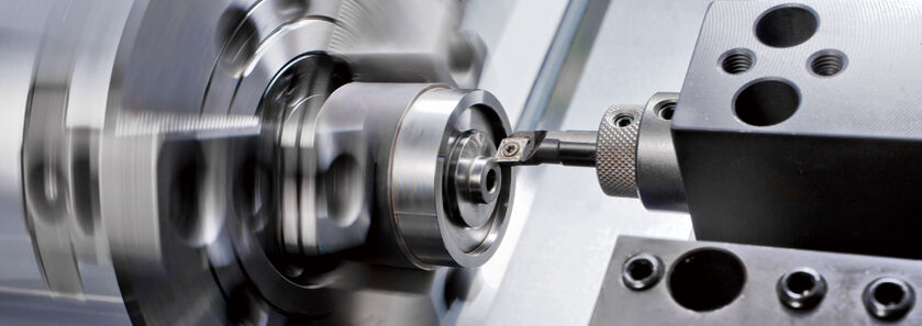
Imagine starting with a solid block of aluminum, steel, or engineering plastic. Now picture carefully removing material—layer by layer, cut by cut—until only your desired shape remains. That's subtractive manufacturing in action, and it's the foundation of how machined parts come to life.
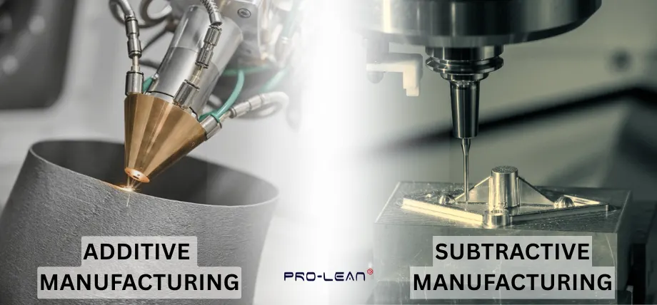
Unlike additive manufacturing (3D printing) that builds objects layer by layer, or casting that pours molten material into molds, machining takes the opposite approach. You begin with more material than you need and precisely remove the excess. This method delivers exceptional dimensional accuracy, often achieving tolerances as tight as ±0.025 mm with modern precision machining services.
The process relies on various cutting operations—milling, turning, drilling, and grinding—each suited to different geometries and requirements. What makes this approach so valuable? The material's original properties remain completely intact since there's no melting or chemical alteration involved.
From Raw Material to Finished Component
So how does a raw block transform into precision machined products ready for assembly? The journey typically follows these steps:
- Material selection: Choosing the right metal or plastic based on mechanical properties, machinability, and application requirements
- CAD/CAM programming: Converting digital designs into machine instructions that guide every cut
- Workholding setup: Securing the raw material firmly to prevent movement during cutting
- Machining operations: Executing programmed cutting paths with precise speed and feed rates
- Quality inspection: Verifying dimensions against specifications before delivery
Each stage demands attention to detail. A single miscalculation in programming or an unstable workholding setup can compromise the entire component.
Why Precision Matters in Machined Parts
Why go through all this trouble when other manufacturing methods exist? The answer lies in what machining delivers that alternatives simply can't match consistently.
Machine components produced through subtractive methods offer superior surface finishes—critical when parts must seal against fluids or mate precisely with other components. They also provide dimensional consistency that's essential in aerospace, medical devices, and automotive applications where failure isn't an option.
Consider this: casting may produce a part close to final shape faster, but it often introduces porosity, shrinkage, or surface irregularities requiring secondary finishing. Machined parts, by contrast, come off the machine ready for assembly in many applications. When your project demands tight tolerances, reliable material properties, and surfaces measured in micrometers rather than millimeters, machining becomes the clear choice.
Essential CNC Machining Processes for Part Production
Now that you understand how parts machined through subtractive manufacturing come to life, which specific process should you choose? The answer depends entirely on your part's geometry, size, and precision requirements. Let's break down the three primary CNC machining processes that manufacturers rely on daily.
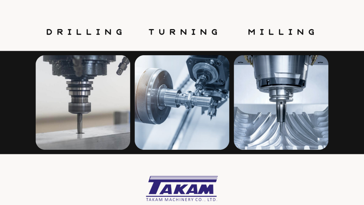
CNC Milling for Complex Geometries
Picture a cutting tool spinning at thousands of RPM while moving across a stationary workpiece. That's CNC milling—and it's your go-to process when parts require flat surfaces, pockets, slots, or intricate three-dimensional contours.
But not all milling machines are created equal. The number of axes determines what geometries you can achieve:
- 3-axis milling: The cutting tool moves along X, Y, and Z axes. Perfect for planar profiles, drilling, and threaded holes aligned with a single axis. Most cost-effective for simpler projects, but limited when you need angled features or undercuts.
- 4-axis milling: Adds a rotary A-axis that rotates around the X-axis. This enables continuous cutting along arcs and creation of complex profiles like helixes and cam lobes without multiple setups. Ideal for parts requiring features on multiple sides.
- 5-axis milling: Incorporates two rotary axes, providing maximum flexibility. The cutting tool can approach the workpiece from virtually any angle, enabling the most complex geometries with superior surface finishes in fewer operations.
When does each make sense? A 3-axis machine handles most straightforward CNC milled components economically. But if your design includes angled holes, curved surfaces, or features on multiple faces, stepping up to 4-axis or 5-axis capability eliminates costly fixture changes and reduces cycle times. The trade-off? Higher machine rates—so match complexity to actual requirements rather than defaulting to maximum capability.
CNC Turning for Rotational Parts
Sounds complex? CNC turning actually follows a simple principle: the workpiece rotates while stationary cutting tools remove material. This makes it the natural choice for cylindrical or round components—shafts, pins, bushings, and any part where rotational symmetry dominates the geometry.
During CNC turning operations, the machine spindle grips bar stock and rotates it at high speed. As the workpiece spins, cutting tools mounted on a turret move along programmed paths to create external diameters, internal bores, threads, and grooves. Modern CNC turning services often include live tooling capabilities, allowing milling operations on the lathe for features like cross-holes or flats without transferring the part to a second machine.
- Ideal applications: Shafts, pins, spacers, threaded fasteners, hydraulic fittings, and any component with predominantly round cross-sections
- Typical tolerances: Standard turning achieves ±0.05 mm easily, with precision setups reaching ±0.01 mm
- Material considerations: Works efficiently with metals and plastics; bar stock feeds automatically for high-volume production
CNC turned parts often cost less than equivalent milled components when geometry permits. Why? The continuous cutting action during turning removes material faster than intermittent milling cuts, and bar feeders enable lights-out production for extended runs.
Swiss Machining for Micro Components
When your design calls for small, slender parts with exceptional precision, standard CNC lathes run into limitations. Enter Swiss machining—a specialized turning process originally developed for watchmaking that excels at producing tiny, intricate components.
What makes Swiss machines different? The key innovation is a guide bushing that supports the workpiece immediately adjacent to where the CNC cuts occur. According to industry comparisons, this support system significantly reduces part deflection, enabling the machine to hold tighter tolerances and produce smoother surfaces on long, slender components with length-to-diameter ratios exceeding 3:1.
- Optimal part size: Typically under 32mm diameter, though some machines handle slightly larger stock
- Precision advantage: Guide bushing support eliminates deflection issues that plague conventional lathes on small parts
- Production efficiency: Built-in bar feeding and part collection allow extended unattended operation
- Common applications: Medical implant screws, electronic connector pins, aerospace fasteners, dental components, and precision instrument parts
Swiss machining does come with higher initial setup costs and requires specialized programming expertise. However, for high-volume production of small precision components, the per-part cost often drops below what conventional CNC cutting would achieve—especially when you factor in reduced scrap rates and eliminated secondary operations.
Choosing the right process isn't about finding the most advanced machine available. It's about matching your part's specific geometry, tolerance requirements, and production volume to the process that delivers quality most efficiently. With these foundational processes understood, you're ready to tackle the next critical decision: selecting materials that perform under real-world conditions.
Material Selection Guide for Machined Components
You've selected the right machining process for your part geometry. Now comes an equally critical decision: which material gives you the performance you need without blowing your budget or extending lead times? Material selection affects everything—from how quickly the machine can cut to how your finished component performs under stress, heat, or corrosive environments.
The options fall into two broad categories: metals and engineering plastics. Each brings distinct advantages depending on your application's demands for strength, weight, thermal performance, and chemical resistance.
Aluminum and Steel Selection Criteria
When engineers specify metals for parts machined on CNC equipment, aluminum and steel dominate the conversation—and for good reason. These materials offer proven performance across countless applications while remaining readily available and reasonably priced.
Aluminum stands out as the workhorse material for aluminum machining projects. Its combination of lightweight construction, excellent machinability, and natural corrosion resistance makes it ideal for prototyping and production alike. According to industry analysis, aluminum 6061 delivers the best overall performance for general-use parts where moderate strength and low cost matter most.
- 6061 aluminum: The most commonly machined grade, offering good strength, weldability, and anodizing characteristics
- 7075 aluminum: Significantly stronger than 6061, preferred for aerospace and high-stress structural applications
- 2024 aluminum: Excellent fatigue resistance, commonly used in aircraft structures
Steel and stainless steel enter the picture when strength and durability requirements exceed what aluminum can deliver. While machining takes longer and tool wear increases, the payoff comes in mechanical performance.
- 1018 mild steel: Easy to machine and weld, suitable for low-stress structural components
- 4140 alloy steel: Heat-treatable for increased hardness, common in automotive and industrial machinery
- 303 stainless steel: Best machinability among stainless grades, ideal for fittings and fasteners
- 316 stainless steel: Superior corrosion resistance justifies higher machining costs when durability or hygiene is paramount
Titanium occupies the premium tier—expensive and challenging to machine, but unmatched when weight savings and strength must coexist. Aerospace, medical implants, and high-performance motorsports justify its cost. Brass and bronze offer excellent wear resistance and natural lubricity, making machining bronze an attractive option for bearings, bushings, and decorative hardware.
Engineering Plastics for Machined Components
Why consider plastics when metals seem so versatile? Engineering plastics deliver advantages that metals simply can't match in certain applications. They're lighter, often more corrosion-resistant, electrically insulating, and—importantly—machine more quickly with less tool wear.
Delrin (POM/Acetal) ranks among the most popular choices for precision machined plastic components. This polyacetal delrin material offers exceptional dimensional stability, low friction, and excellent wear resistance. The delrin plastic machines cleanly without the heat-related issues plaguing some other polymers. You'll find delrin material in gears, bearings, bushings, and any application requiring consistent performance under repeated motion.
Acetal plastic comes in two forms: homopolymer (Delrin) and copolymer. Homopolymer versions offer slightly higher strength and stiffness, while copolymers provide better chemical resistance and dimensional stability in humid environments.
Nylon brings wear resistance and toughness to the table. When considering nylon for machining, keep in mind its moisture absorption characteristics—parts may change dimensions slightly in humid environments. Despite this consideration, nylon excels in applications requiring impact resistance and flexibility.
PEEK (Polyether Ether Ketone) represents the high-performance end of engineering plastics. It withstands temperatures exceeding 250°C, resists most chemicals, and offers strength approaching some metals. Medical devices, aerospace components, and semiconductor equipment commonly specify PEEK when extreme conditions demand it.
- Polycarbonate: Optical clarity combined with impact resistance; ideal for protective covers and display windows
- PTFE (Teflon): Unmatched chemical resistance and low friction for seals and gaskets
- ABS: Cost-effective option for housings and enclosures with good impact resistance
Matching Materials to Application Requirements
Choosing the right material isn't about picking the strongest or cheapest option—it's about matching properties to your specific application demands. Consider these key factors:
- Mechanical loads: Will the part experience tension, compression, bending, or fatigue cycles?
- Operating environment: Temperature extremes, moisture exposure, or chemical contact?
- Weight constraints: Is minimizing mass critical, as in aerospace or portable devices?
- Production volume: Higher volumes justify premium materials if machining efficiency improves
- Budget limitations: Raw material cost, machining time, and tool wear all factor into total part cost
| Material | Machinability Rating | Typical Applications | Relative Cost |
|---|---|---|---|
| Aluminum 6061 | Excellent (90%) | General mechanical parts, prototypes, enclosures | Low |
| Aluminum 7075 | Good (70%) | Aerospace structures, high-stress components | Medium |
| 303 Stainless Steel | Good (65%) | Fittings, fasteners, shafts | Medium |
| 316 Stainless Steel | Moderate (45%) | Marine, medical, food processing equipment | Medium-High |
| Titanium Grade 5 | Poor (25%) | Aerospace, medical implants, motorsports | High |
| Brass | Excellent (100%) | Fittings, decorative hardware, electrical contacts | Medium |
| Delrin (POM) | Excellent | Gears, bearings, bushings, precision mechanisms | Low-Medium |
| Nylon | Good | Wear parts, structural components, insulators | Low |
| PEEK | Good | Medical devices, aerospace, semiconductor | Very High |
For small-batch production or prototyping, materials like aluminum and brass reduce risk and cost due to shorter machine times and easier setups. When scaling to higher volumes, even materials with moderate machinability become viable if the application demands their properties.
With material selection clarified, your next challenge involves specifying exactly how precise those parts need to be. Understanding tolerance classes and their real-world implications helps you balance precision requirements against manufacturing costs.
Tolerances and Precision Standards for Machined Parts
You've selected your material. Now comes the question that directly impacts both cost and functionality: how precise does your part actually need to be? Specifying tolerances too loosely risks parts that won't fit or function correctly. Over-specify, and you're paying for precision you don't need.
Understanding tolerance classes—and what they mean practically—separates engineers who get reliable quotes from those who waste time and budget on unnecessary precision. Let's break down how tolerances work for precision machined parts and when tighter specs justify their cost.
Understanding Tolerance Classes and Their Applications
Think of tolerances as the permissible wiggle room in any dimension. When you specify a 50mm feature, manufacturing variations mean the actual dimension might measure 49.95mm or 50.05mm. Tolerance classes define exactly how much variation is acceptable.
Two ISO standards govern most precision machined components: ISO 2768 for general tolerances and ISO 286 for specific features requiring tighter control. According to industry standards, ISO 2768 applies by default to machined parts unless drawings explicitly call out tighter requirements.
ISO 2768 offers two practical tolerance classes for linear dimensions:
- Medium (m): The standard starting point for most machined parts. For a 50mm dimension, expect ±0.3mm deviation.
- Fine (f): Tighter control when fit matters more. That same 50mm dimension now holds ±0.15mm.
When do you need to step beyond general tolerances? Features like bearing fits, mating surfaces, and threaded connections often demand ISO 286 specifications. This standard uses IT grades (IT6, IT7, IT8) to define progressively tighter tolerance bands.
| Tolerance Standard | Typical Range (50mm nominal) | Best Applications | Cost Impact |
|---|---|---|---|
| ISO 2768-m (Medium) | ±0.3mm | General structural parts, enclosures, non-critical features | Baseline |
| ISO 2768-f (Fine) | ±0.15mm | Functional fits, assembly interfaces, visible surfaces | +10-20% |
| ISO 286 IT8 | ±0.039mm | Sliding fits, location pins, moderate precision assemblies | +25-40% |
| ISO 286 IT7 | ±0.025mm | Precision fits, bearing seats, shaft/housing interfaces | +50-75% |
| ISO 286 IT6 | ±0.016mm | High-precision assemblies, instrument components | +100%+ |
What about specific features like threaded holes? If you're wondering what is the tolerance for thread holes, the answer depends on thread class. For example, 3/8 NPT thread dimensions follow ANSI/ASME B1.20.1 standards, with specific tolerances for pitch diameter and thread form. Similarly, 1 4 NPT hole size specifications dictate both the tap drill diameter and acceptable thread engagement depth.
When Tight Tolerances Are Worth the Investment
Here's what many engineers overlook: not every feature on your part needs the same tolerance class. A housing might require IT7 precision where a shaft passes through, while the outer dimensions only need ISO 2768-m. Applying tight tolerances universally wastes money without improving function.
Tight tolerances justify their cost when:
- Parts must interface precisely: Bearing seats, press fits, and alignment features where clearance or interference directly affects performance
- Assembly depends on exact positioning: Bolt patterns, locating pins, and mating surfaces that must align across multiple components
- Motion or sealing is involved: Sliding fits, rotating shafts, and O-ring grooves where dimensional variation causes binding, leakage, or premature wear
- Safety-critical applications: Aerospace, medical, and automotive components where failure creates unacceptable risk
Conversely, applying IT6 precision to a mounting bracket's outer edges adds cost without benefit. The part functions identically whether that edge measures 100.00mm or 100.25mm.
For precision machining parts, this selective approach to tolerancing—tight where function demands, relaxed where it doesn't—represents the sweet spot between quality and economy.
Surface Finish Specifications Explained
Beyond dimensional tolerances, surface finish significantly impacts how precision machined components perform. A bearing surface requires smoothness that a mounting face doesn't. Specifying finishes correctly prevents both over-processing and functional failures.
Surface finish is typically measured in Ra (roughness average) values, expressed in micrometers (μm) or microinches (μin). Lower numbers mean smoother surfaces:
- Ra 3.2μm (125μin): Standard machined finish. Adequate for most structural parts and non-critical surfaces. Visible tool marks present.
- Ra 1.6μm (63μin): Fine machined finish. Suitable for mating surfaces, bearing journals, and components requiring better appearance.
- Ra 0.8μm (32μin): Precision finish requiring careful tool selection and speeds. Used for hydraulic components, sealing surfaces, and precision fits.
- Ra 0.4μm (16μin): Ground or lapped finish. Essential for high-precision bearings, gauges, and optical mounting surfaces.
Surface finishes interact with tolerances in important ways. Achieving Ra 0.4μm on a feature while holding IT8 positional tolerance requires compatible processes—grinding or precision milling rather than standard turning. Specifying mismatched combinations creates manufacturing headaches and drives costs upward.
The most cost-effective approach to tolerancing: specify the loosest tolerance that still guarantees function, applied only to features where that function depends on dimensional accuracy.
Geometric Dimensioning and Tolerancing (GD&T) extends beyond simple linear dimensions to control feature geometry—flatness, perpendicularity, position, and runout. According to GD&T standards, this system communicates not just size but shape, location, and alignment so parts work exactly as intended.
GD&T proves essential when:
- Two surfaces must mate flat without gaps (flatness control)
- Holes must align precisely for bolt patterns (position tolerance)
- Shafts must run true without wobble (runout control)
- Features must maintain specific angular relationships (perpendicularity, angularity)
While GD&T adds drawing complexity, it prevents the costly ambiguity that leads to rejected parts or failed assemblies. For critical-to-function features on precision machined components, the upfront investment in proper tolerancing pays dividends through reduced rework and reliable performance.
With tolerances understood, you're ready to tackle design decisions that directly impact both manufacturability and cost. The next section covers DFM principles that help you create parts optimized for machining from the start.
Design Principles That Optimize Machined Part Production
You've specified tolerances and selected materials. But here's what separates good designs from great ones: how well your part geometry aligns with real machining capabilities. Designing custom machined parts without considering manufacturing constraints leads to inflated quotes, extended lead times, and quality compromises that could have been avoided from the start.
Design for manufacturability (DFM) isn't about limiting creativity—it's about making smart choices that keep your CNC machining parts cost-effective while maintaining full functionality. Let's walk through the principles that experienced engineers apply before their designs ever reach a machine shop.
Critical Design Features That Reduce Machining Costs
Every feature you add to a part requires time, tooling, and potentially additional setups. Understanding which design choices drive costs helps you make informed trade-offs early in development.
The most expensive machining part is one designed without manufacturing in mind. Up to 80% of production cost gets locked in during the design phase—before a single chip is cut.
Start with these fundamental DFM rules that apply across most machining parts:
- Wall thickness: According to established guidelines, aluminum walls should measure at least 1.0-1.5mm thick, while stainless steel requires 1.5-2.5mm minimum. Plastics need even more—typically 2.0-3.0mm—to prevent warping during cutting. Thinner walls vibrate under tool pressure, causing chatter marks and tolerance drift.
- Internal corner radii: End mills are cylindrical, which means they physically cannot create perfectly sharp internal corners. Design internal radii equal to or slightly larger than the tool radius—typically 1/3 of the pocket depth works well. Sharp corners force slower toolpaths, custom cutters, or secondary EDM operations.
- Hole depth-to-diameter ratios: Keep hole depths within 6x the diameter for predictable chip evacuation and accuracy. A 10mm hole drilled 60mm deep works fine; that same hole at 80mm depth risks tool breakage and dimensional problems.
- Pocket depths: Limit pocket depth to roughly 4x the tool diameter. Deeper pockets require slender cutters that deflect, reducing accuracy and surface quality while increasing cycle time.
- Feature accessibility: Every feature must be reachable by standard cutting tools. Consider tool length, holder clearance, and approach angles. A beautifully designed internal feature means nothing if no tool can physically reach it.
When specifying holes for fasteners—like a through hole for a 4 m bolt—use standard drill sizes whenever possible. Non-standard diameters require reaming or interpolation, adding time and cost to every CNC machine parts order.
Common Design Mistakes and How to Avoid Them
Even experienced engineers fall into traps that complicate manufacturing. Watch for these frequent issues when creating machining parts:
- Deep, narrow pockets: These geometries force long, thin tools that deflect and vibrate. If you need deep features, widen them to accommodate larger, more rigid cutters—or add internal steps to buttress thin walls.
- Tall, thin walls adjacent to pockets: Unsupported walls flex during cutting, causing dimensional inaccuracy and poor surface finish. Either thicken walls or reduce pocket depth to maintain rigidity.
- Unnecessary tight tolerances: Applying precision specifications universally rather than selectively wastes money. Standard machining holds ±0.10mm easily; reserve tighter callouts for functional features only.
- Undercuts without purpose: Internal undercuts often require special tooling, additional setups, or multi-axis capability. Eliminate them unless function absolutely demands it.
- Ignoring standard sizes: Specifying a 7.3mm hole when 7mm works functionally identical adds cost. Standard drill bits, taps, and reamers exist for common sizes—use them.
Thread design deserves special attention. According to manufacturing guidelines, most metal threads achieve full strength at just 3x the diameter. Deeper threading adds machining time without functional benefit. For soft plastics, consider threaded inserts instead—they provide better durability than threads cut directly into polymer material.
Optimizing Part Geometry for Production
Beyond avoiding mistakes, proactive optimization separates cnc prototype designs that fly through production from those requiring constant engineering changes.
Consider these geometry optimization strategies:
- Favor chamfers over external radii: While internal corners require radii, external edges benefit from 45° chamfers. They're faster to machine, improve handling safety, and look clean. Save radii for functional requirements like stress distribution.
- Design for minimal setups: Every time a part must be repositioned, setup time and potential misalignment accumulate. Organize features so most or all can be machined from one or two orientations.
- Include appropriate draft: While machining doesn't require draft angles like casting, slight tapers on deep pockets improve tool access and chip evacuation.
- Standardize features: Using the same hole size, corner radius, and thread specification throughout a part reduces tool changes. Fewer tools mean faster cycles and lower costs.
- Consider fixturing: Flat reference surfaces for clamping, adequate material for workholding, and stable geometries that won't tip or rotate under cutting forces all contribute to successful production.
Material choice interacts with geometry decisions. Aluminum forgives thin features and deep pockets better than stainless steel, which generates more heat and cutting force. When designing for harder materials, build in extra wall thickness and avoid aggressive depth-to-width ratios that work fine in softer alloys.
The payoff for DFM attention shows up immediately: faster quotes, shorter lead times, and parts that arrive ready for assembly rather than requiring rework. As you move from cnc prototype validation toward production volumes, these principles compound—saving significant cost across every unit manufactured.
With design optimization covered, the next question becomes whether CNC machining is even the right process for your application. Understanding how machining compares to alternative manufacturing methods helps you make that strategic decision with confidence.
CNC Machining Compared to Alternative Manufacturing Methods
You've optimized your design for machining. But here's a question worth asking before committing: is CNC machining actually the best process for your specific application? Sometimes it absolutely is. Other times, alternative methods deliver equivalent results faster, cheaper, or with capabilities machining simply can't match.
Making the right choice requires understanding what each manufacturing method does best—and where it falls short. Let's compare CNC machined parts against the major alternatives so you can make informed decisions rather than defaulting to familiar territory.
CNC Machining Versus 3D Printing
This comparison comes up constantly, and for good reason. Both processes can produce complex geometries from digital files. But they work in fundamentally opposite ways—and that difference matters enormously depending on your requirements.
3D printing builds parts layer by layer from nothing, adding material only where needed. CNC prototyping removes material from solid blocks. According to Protolabs' manufacturing comparison, 3D printing excels at rapid prototyping with quick turnaround times and lower costs for initial iterations, while CNC machining delivers when high precision and tight tolerances are essential.
When does 3D printing make more sense?
- Complex internal geometries: Lattice structures, internal cooling channels, and organic shapes that tools physically cannot reach
- Rapid iteration: When you're testing multiple design variations quickly and cost matters more than final material properties
- Lightweighting applications: Structures optimized through topology software that would be impossible to machine conventionally
- Low quantities of complex parts: One-off prototypes or small batches where machining setup costs dominate
When should you stick with CNC fabrication?
- Material performance is critical: Machined parts retain full material properties—no layer lines, no porosity, no anisotropic weaknesses
- Precision requirements exceed ±0.1mm: Most 3D printing technologies struggle to match standard machining tolerances
- Surface finish matters: Machined surfaces typically require less post-processing than printed equivalents
- Production volumes justify setup: Once programmed, CNC machines produce consistent parts faster than most printers
For titanium components, you might encounter options like titanium DMLS/CNC. DMLS (Direct Metal Laser Sintering) prints the rough shape, then CNC machining finishes critical surfaces to specification. This hybrid approach captures the geometric freedom of printing with the precision of machining.
When Casting or Molding Makes More Sense
Machining removes material you've already paid for. At high volumes, that wasted material—plus the machine time to remove it—adds up quickly. Casting and injection molding flip this equation by producing parts closer to net shape from the start.
Casting works by pouring molten metal into molds. Investment casting, die casting, and sand casting each serve different volume and complexity requirements. The trade-off? Tooling costs. A die casting mold might cost $10,000-$50,000, but amortized across 100,000 parts, that's pennies per unit. For 50 parts? CNC machined parts win hands down.
Injection molding dominates plastic part production at scale. According to industry analysis, injection molding is ideal for high-volume production and complex geometries with detailed features, while cnc plastic machining suits lower quantities or materials that don't mold well.
Consider injection molding when:
- Annual volumes exceed 1,000-5,000 units (threshold varies by part complexity)
- Parts require snap fits, living hinges, or other mold-friendly features
- Material selection includes commodity plastics like ABS, PP, or PE
- Consistent cosmetic appearance across thousands of units matters
Stick with machining when:
- Quantities stay below injection molding's break-even point
- Engineering plastics like PEEK or Ultem are specified (many don't mold well)
- Tolerances exceed typical molding capability (±0.1-0.2mm for precision molds)
- Design changes remain likely—mold modifications are expensive
Sheet metal fabrication offers another alternative for enclosures, brackets, and panels. Laser cutting, bending, and welding produce parts faster and cheaper than machining equivalent geometries from solid blocks—provided your design suits sheet construction.
Decision Framework for Manufacturing Method Selection
Rather than defaulting to one process, evaluate each project against these key criteria:
| Criteria | CNC Machining | 3D Printing | Injection Molding | Casting |
|---|---|---|---|---|
| Ideal Volume | 1-10,000 units | 1-500 units | 5,000+ units | 500-100,000+ units |
| Precision Capability | ±0.025mm achievable | ±0.1-0.3mm typical | ±0.1mm with precision molds | ±0.25-1.0mm depending on method |
| Material Options | Metals, plastics, composites | Limited polymers, some metals | Most thermoplastics | Most metals and alloys |
| Lead Time (First Part) | 1-10 days | 1-5 days | 2-8 weeks (tooling) | 4-12 weeks (tooling) |
| Tooling Investment | None | None | $5,000-$100,000+ | $1,000-$50,000+ |
| Design Flexibility | High (with DFM constraints) | Very high | Moderate (mold constraints) | Moderate (draft, wall thickness) |
| Best For | Prototypes to mid-volume production, precision parts | Rapid prototypes, complex geometries | High-volume plastic parts | High-volume metal parts |
The decision often comes down to three questions:
- How many parts do you need? Low volumes favor prototype machining; high volumes favor molding or casting
- How precise must they be? Tight tolerances push toward CNC regardless of volume
- How quickly do you need them? Machining and printing deliver fast; tooled processes require patience upfront
Many successful products use multiple processes across their lifecycle. CNC prototyping validates designs quickly. Once proven, injection molds or casting tooling scale production economically. Critical features might still get machined even on cast or molded parts—combining processes to capture each method's strengths.
Understanding these trade-offs positions you to specify the right process from the start rather than discovering mid-project that an alternative would have served better. With manufacturing method selection clarified, the next consideration becomes what happens after parts come off the machine—the secondary operations and finishing processes that complete your components.
Secondary Operations and Finishing for Machined Parts
Your part comes off the CNC machine dimensionally accurate and functionally shaped. But is it truly complete? For many applications, raw machined components need secondary operations to achieve their final performance characteristics. Whether you're protecting against corrosion, enhancing wear resistance, or meeting aesthetic requirements, finishing processes transform machined products into ready-for-service components.
Understanding which finish suits your application—and why—prevents both over-specification that wastes budget and under-specification that leads to premature failure. Let's explore the finishing options that complete metal machining projects across industries.
Protective Coatings and Surface Treatments
Different base materials require different protection strategies. The coating that works perfectly on aluminum won't necessarily suit steel—and applying the wrong finish can actually cause problems rather than solve them.
Aluminum finishing options:
- Anodizing (Type II): Creates a controlled oxide layer integrated with the base material—it won't chip or flake like paint. According to industry guidelines, anodizing improves corrosion resistance, enables dyeing for color options, and makes aluminum electrically non-conductive. Ideal for consumer electronics, architectural components, and any visible machined components.
- Anodizing (Type III/Hardcoat): Thicker, harder coating than Type II. Provides excellent wear resistance for functional surfaces subject to abrasion or repeated contact.
- Chromate conversion (Alodine/Chem film): Thinner, cheaper alternative that maintains electrical and thermal conductivity. Works well as a primer for painting or when conductivity matters. The gold or iridescent finish is prone to scratching but provides solid corrosion protection.
Steel and stainless steel finishing options:
- Passivation: Essential for stainless steel machined components. This chemical treatment removes free iron from the surface, forming a protective chromium oxide layer just one to three nanometers thick—enough to prevent corrosion when conditions remain stable. Passivation adds no dimensional change, so masking isn't required.
- Black oxide: Creates a magnetite layer on ferrous metals, providing mild corrosion resistance and a smooth, matte black appearance. Often combined with oil sealing for enhanced protection. Dimensional impact is negligible.
- Zinc plating (galvanization): Protects steel from corrosion through sacrificial action—zinc corrodes preferentially, protecting the underlying steel even when the coating is scratched. Common for fasteners and structural components.
- Electroless nickel plating: Deposits a uniform nickel-phosphorus coating without electrical current. Higher phosphorus content improves corrosion resistance; lower phosphorus increases hardness. Works on aluminum, steel, and stainless steel alike.
Multi-material finishing options:
- Powder coating: Applied electrostatically and oven-cured, creating a thick, durable finish in virtually any color. Works on steel, stainless steel, and aluminum. Adds measurable thickness (typically 0.05-0.1mm), so critical dimensions require masking. Excellent for enclosures and visible housings.
- Media blasting: Creates uniform matte textures by firing glass beads, aluminum oxide, or other abrasives at the surface. Often used before other finishes to hide machining marks. Combining media blasting with anodizing produces the smooth, matte aesthetic found on premium consumer electronics.
For plastic machined components like cnc polycarbonate parts, finishing options differ. Polycarbonate PC typically receives vapor polishing for optical clarity or light media blasting for uniform matte appearance. Unlike metals, plastics rarely need corrosion protection—but scratch resistance and UV stability often require consideration.
Heat Treatment for Enhanced Performance
When machined components need hardness, strength, or wear resistance beyond what raw material provides, heat treatment fills the gap. These processes alter material microstructure through controlled heating and cooling cycles.
- Case hardening: Hardens the outer layer while maintaining a tough core. Ideal for gears, shafts, and wear surfaces that need both surface hardness and impact resistance.
- Through hardening: Increases hardness throughout the entire part. Used when uniform properties matter more than toughness.
- Stress relieving: Reduces internal stresses from machining without significantly changing hardness. Improves dimensional stability for precision components.
- Annealing: Softens material for improved machinability or subsequent forming operations.
Timing matters with heat treatment. Some processes—like electroless nickel plating—should only be applied after heat treatment to preserve the coating's corrosion-resistant properties. Discuss sequencing with your finishing supplier to avoid compromising either the treatment or the coating.
Selecting the Right Finish for Your Application
Choosing finishes isn't just about protection—it's about matching the finish to your specific operating environment and functional requirements. Ask these questions:
- What environment will the part encounter? Marine applications demand aggressive corrosion protection; indoor electronics might need only basic passivation or anodizing.
- Does the surface contact other components? Wear surfaces benefit from hardcoat anodizing or electroless nickel; non-contact surfaces rarely need such treatment.
- Are there dimensional constraints? Coatings that add thickness require masking on tight-tolerance features, threaded holes, and mating surfaces. Passivation and black oxide add negligible dimension changes.
- What appearance matters? Visible components often specify cosmetic finishes; internal parts can prioritize function over aesthetics.
- What's the budget impact? Chromate conversion costs less than anodizing; passivation costs less than plating. Match protection level to actual need.
Multiple finishes can work together. Media blasting before anodizing improves appearance. Passivation before black oxide enhances both corrosion resistance and aesthetics on steel. Understanding these combinations helps you specify exactly what your machined products need to perform reliably in service.
With finishing processes understood, the next consideration becomes how industry-specific requirements and certifications shape quality standards for different sectors—from automotive to aerospace to medical devices.
Industry Standards and Certifications for Machined Parts
Your parts machined to specification, finished to protect against wear—but are they certified for your industry? Different sectors impose vastly different requirements on manufactured components. What passes inspection in general industrial applications might fail immediately in aerospace, automotive, or medical contexts. Understanding these industry-specific standards before you source parts prevents costly rejections and production delays.
Each industry has developed certification frameworks that reflect its unique risks and quality demands. An automotive supplier faces different pressures than an aerospace manufacturer, and both operate under stricter oversight than general industrial machining. Let's examine what each major sector requires—and why these standards exist.
Automotive Industry Machining Standards
Automotive manufacturing operates at volumes and speeds that demand exceptional process control. When you're producing thousands of identical components daily, statistical variation becomes your primary enemy. That's where IATF 16949 certification comes in.
IATF 16949 builds on ISO 9001's foundation but adds automotive-specific requirements that address the industry's unique challenges. According to Hartford Technologies, this global quality management standard encompasses product design, production processes, improvement, and customer-specific standards—ensuring compliance with stringent industry regulations.
Key requirements under IATF 16949 include:
- Statistical Process Control (SPC): Continuous monitoring of production variables to catch drift before it creates defects. Control charts, capability studies, and real-time measurement integration are standard practice.
- Production Part Approval Process (PPAP): Formal documentation proving your process can consistently produce parts meeting specifications before mass production begins.
- Failure Mode and Effects Analysis (FMEA): Systematic identification of potential failures and their consequences, with documented prevention measures.
- Advanced Product Quality Planning (APQP): Structured approach to product development that prevents quality issues rather than detecting them after the fact.
- Customer-specific requirements: Major OEMs layer additional standards on top of IATF 16949, requiring suppliers to meet manufacturer-specific protocols.
For automotive chassis assemblies, suspension components, and powertrain parts, these requirements aren't optional—they're table stakes for participating in the supply chain. IATF 16949 certified facilities like Shaoyi Metal Technology meet these demands through integrated Statistical Process Control and rapid lead times, delivering precision components for chassis assemblies while maintaining the documentation rigor automotive OEMs expect.
Volume expectations also shape automotive machining. Unlike aerospace's lower quantities of highly complex parts, automotive demands high-volume production with minimal variation. CNC service providers serving this sector must demonstrate not just capability but repeatability across tens of thousands of units.
Aerospace and Defense Requirements
When components fly at 30,000 feet or operate in defense applications, failure consequences escalate dramatically. Aerospace cnc machining operates under AS9100 certification—a standard that adds aerospace-specific requirements to the ISO 9001 foundation.
AS9100 addresses risks unique to aviation and defense:
- Complete material traceability: Every component must trace back to specific material lots, heat numbers, and mill certifications. If a problem emerges years later, manufacturers must identify exactly which parts might be affected.
- First Article Inspection (FAI): Comprehensive dimensional verification of initial production parts against design specifications, documented per AS9102 requirements.
- Configuration management: Strict control over design changes, ensuring that approved configurations don't drift over time.
- Foreign Object Debris (FOD) prevention: Documented programs preventing contamination that could cause in-flight failures.
- Counterfeit parts prevention: Verification systems ensuring only authentic, certified materials enter the supply chain.
CNC machining aerospace components also requires specialized process capabilities. According to industry analysis, aerospace parts often demand tolerances as tight as ±0.0001 inches (2.54 micrometers) for critical components—far beyond standard machining capability.
Material documentation takes on heightened importance in aerospace machining. Titanium, Inconel, and specialized aluminum alloys require certified test reports proving mechanical properties meet specification. Heat lot traceability, material composition verification, and processing certifications form an unbroken chain from raw material to finished component.
Precision cnc machining services targeting aerospace must also address special process controls. Heat treatment, plating, and non-destructive testing often require Nadcap accreditation—an additional layer of process validation beyond AS9100 requirements.
Medical Device Manufacturing Compliance
Medical machining faces perhaps the most demanding regulatory environment of any sector. Components that contact human tissue or support life-critical functions require absolute assurance of safety and performance.
ISO 13485 serves as the cornerstone certification for medical device machining. Unlike ISO 9001's focus on customer satisfaction, ISO 13485 prioritizes patient safety and regulatory compliance. According to industry standards, this certification ensures all medical devices are designed and manufactured with safety in mind, involving rigorous inspections and closely aligning with ISO 9001 while addressing unique medical industry requirements.
Key requirements for medical device machining include:
- Design controls: Documented design and development processes with verification and validation at each stage.
- Biocompatibility verification: Materials contacting tissue must demonstrate compatibility through ISO 10993 testing protocols. Titanium, 316L stainless steel, PEEK, and medical-grade polymers dominate material selections.
- Sterility assurance: Components requiring sterilization must validate that processes achieve required sterility assurance levels without degrading materials.
- Risk management: ISO 14971 compliance documenting hazard identification, risk assessment, and mitigation throughout the product lifecycle.
- Complete traceability: Every component must trace to specific material lots, manufacturing dates, equipment, and operators.
FDA registration adds U.S.-specific requirements beyond ISO 13485. The Quality System Regulation (21 CFR Part 820) mandates design history files, device master records, and complaint handling systems that create comprehensive documentation trails.
Surface finish requirements for medical machining often exceed other industries. Implantable devices typically require Ra values between 0.1-0.4 μm to prevent bacterial colonization and tissue irritation. Surgical instruments need finishes that withstand repeated sterilization without degradation.
Cleanroom manufacturing becomes necessary for many medical components. Controlled environments classified by ISO 14644-1 standards prevent particulate contamination that could compromise patient safety.
| Industry | Primary Certification | Key Requirements | Documentation Focus |
|---|---|---|---|
| Automotive | IATF 16949 | SPC, PPAP, FMEA, high-volume consistency | Process capability studies, control plans |
| Aerospace | AS9100 | Material traceability, FAI, configuration control | Mill certs, heat lot records, FAI reports |
| Medical | ISO 13485 | Design controls, biocompatibility, sterility | Device history records, risk analysis |
| General Industrial | ISO 9001 | Quality management system fundamentals | Inspection reports, calibration records |
Beyond these primary certifications, industry-specific approvals may apply. Defense contracts often require ITAR compliance for export-controlled items. European medical devices need CE marking under MDR regulations. Automotive suppliers to specific OEMs face customer-specific requirements layered on top of IATF 16949.
Understanding which certifications your application demands—before requesting quotes—prevents wasted effort on suppliers who can't meet your regulatory requirements. A precision cnc machining services provider certified for general industrial work may lack the documentation systems, material controls, or process validation that aerospace or medical applications demand.
With industry standards clarified, the next critical decision involves understanding what drives machining costs and how to work effectively with suppliers to optimize both price and quality outcomes.
Cost Factors and Supplier Selection for Machined Parts
You've specified materials, tolerances, and finishing requirements. Now comes the question that ties everything together: what will these parts actually cost, and how do you find a supplier who delivers quality consistently? Understanding cost drivers—and knowing how to work effectively with machining partners—separates procurement professionals who get reliable results from those who face endless surprises.
Whether you're searching for cnc machine shops near me or evaluating global suppliers, the same fundamental factors determine pricing. Let's break down what drives machining costs and how to navigate the supplier relationship from first quote through production scaling.
Key Factors That Determine Machining Costs
There's no universal price list for parts machined on CNC equipment. Every project combines unique variables that collectively determine your final cost. According to Xometry's cost analysis, the most important factors affecting CNC machined parts fall under equipment, materials, design, manufacturing volume, and finishing operations.
Understanding these drivers helps you optimize designs before requesting quotes—and evaluate whether quotes you receive make sense:
- Material cost and machinability: The raw material itself represents a significant portion of part cost. Aluminum machines quickly and costs less than stainless steel or titanium. But beyond purchase price, machinability matters enormously. Hard-to-machine materials consume more time, tooling, and cutting fluids. A titanium part might cost three to five times more than an equivalent aluminum component—not because titanium costs that much more per pound, but because machining takes longer and wears tools faster.
- Part complexity and geometry: Complex parts require more machining time, multiple setups, specialized tooling, and closer inspection. Sharp internal corners, deep pockets, thin walls, and non-standard hole sizes all increase cost. The more advanced machinery required—5-axis versus 3-axis milling, for instance—the higher the hourly rate applied to your job.
- Tolerance requirements: Standard machining tolerances cost baseline rates. Tighter tolerances demand slower cutting speeds, more careful inspection, and potentially specialized equipment. Moving from ±0.1mm to ±0.025mm might double machining time on critical features.
- Quantity and setup amortization: Setup costs—CAD/CAM programming, fixture creation, machine configuration—apply whether you order one part or one thousand. Per-unit costs drop dramatically as quantities increase because setup costs spread across more parts. Industry data shows that cost per unit for production volumes of 1,000 can be approximately 88% less than the cost of a single standalone unit.
- Finishing and secondary operations: Anodizing, plating, heat treatment, and other post-machining processes add both cost and lead time. Each finishing step requires handling, processing time, and often involves specialized suppliers.
When requesting online machining quotes, provide complete information upfront. Incomplete specifications force suppliers to assume worst-case scenarios—inflating quotes unnecessarily. Include material specifications, tolerance callouts, surface finish requirements, quantity needed, and any special certifications required.
Working Effectively with Your Machining Partner
Finding machining shops near me or getting a cnc quote online is just the beginning. The real value comes from building relationships with suppliers who understand your needs and can grow with your requirements.
What should you look for when evaluating local machine shops or custom machine providers?
- Industry experience: A manufacturer familiar with your product type helps avoid costly mistakes. Medical device machining requires different expertise than automotive components, even when the machining operations look similar.
- Equipment capabilities: Verify that the shop has appropriate machines for your parts. Multi-axis capability, Swiss machining, or large-format milling might be necessary depending on your designs.
- Quality systems: Check certifications relevant to your industry. ISO 9001 represents baseline quality management; automotive, aerospace, and medical applications require IATF 16949, AS9100, or ISO 13485 respectively.
- Communication responsiveness: A cnc shop near me that responds quickly to questions and provides transparent feedback on designs often proves more valuable than the cheapest option. Manufacturing problems caught early cost far less to fix than issues discovered after production.
- Scalability: Ensure your supplier can handle volume increases as demand grows. A prototype supplier might lack capacity or cost structure for production quantities.
Request Design for Manufacturability (DFM) feedback before finalizing orders. Good suppliers identify potential issues—tolerance conflicts, hard-to-reach features, material concerns—before machining begins. This collaborative approach prevents expensive rework and strengthens the partnership over time.
Scaling from Prototype to Production
The transition from prototype to production represents one of manufacturing's most challenging phases. According to industry guidance, just because a prototype works doesn't mean it can be easily or affordably mass-produced. Successful scaling requires planning that begins well before your first production order.
Before jumping into production, validate that your prototype design is optimized for manufacturability:
- Design for Manufacturing (DFM) review: Adjust designs to reduce complexity, minimize material waste, and ensure compatibility with production techniques. Features that worked fine for a single prototype might create bottlenecks at volume.
- Material validation: Prototyping materials might not suit full-scale manufacturing. Confirm that your specified material machines efficiently at production rates and meets all performance requirements.
- Process qualification: Production machining may use different equipment than prototyping. Verify that production processes achieve the same quality levels as prototype methods.
Volume transitions also affect cost structure. Prototype quantities absorb full setup costs on just a few parts. Production volumes amortize those costs across hundreds or thousands of units—but may require tooling investments, fixture development, or process automation that add upfront expense.
Suppliers like Shaoyi Metal Technology offer seamless scaling with lead times as fast as one working day, supporting everything from rapid prototyping to high-volume production of components like custom metal bushings. This kind of integrated capability—prototype through production under one roof—eliminates the friction of transitioning between suppliers and ensures consistent quality as volumes grow.
Consider starting with small pre-production runs before committing to high-volume manufacturing. These pilot batches test your production process, validate quality systems, and reveal any issues before they affect thousands of parts. The investment in pre-production validation almost always costs less than discovering problems after full production begins.
Building strong supplier relationships pays dividends beyond immediate cost savings. Reliable partners provide better pricing as relationships mature, prioritize your orders during capacity crunches, and invest in understanding your specific requirements. Whether you're working with a machinist shops near me or a global precision machining provider, treating suppliers as partners rather than vendors creates mutual value that compounds over time.
Frequently Asked Questions About Machined Parts
1. What is a machined part?
A machined part is a precision component created through subtractive manufacturing, where specialized cutting tools remove excess material from a solid block of metal or plastic. Unlike additive methods like 3D printing or casting that shapes molten material, machining preserves the original material properties while achieving tight dimensional tolerances—often as precise as ±0.025mm. Common machining operations include CNC milling, turning, and drilling, producing everything from aerospace components to medical implants.
2. How much does it cost to have parts machined?
CNC machining costs typically range from $50 to $150 per hour depending on equipment complexity and precision requirements. However, total part cost depends on multiple factors: material type and machinability, part complexity, tolerance specifications, quantity ordered, and finishing operations. Importantly, setup costs remain fixed regardless of quantity—meaning per-unit costs can drop approximately 88% when scaling from single prototypes to production volumes of 1,000 units. Suppliers like Shaoyi Metal Technology offer competitive pricing with lead times as fast as one working day.
3. What materials can be CNC machined?
CNC machines work with a wide range of metals and engineering plastics. Popular metals include aluminum (6061, 7075), stainless steel (303, 316), mild steel, titanium, brass, and bronze—each offering different balances of strength, machinability, and corrosion resistance. Engineering plastics like Delrin (POM), nylon, PEEK, and polycarbonate serve applications requiring lighter weight, electrical insulation, or chemical resistance. Material selection should match your application's mechanical loads, operating environment, and budget constraints.
4. What tolerances can CNC machining achieve?
Standard CNC machining easily holds ±0.1mm tolerances, while precision setups achieve ±0.025mm or tighter. Tolerance classes follow ISO 2768 for general dimensions (medium and fine grades) and ISO 286 for critical features requiring IT6-IT8 precision. Tighter tolerances increase cost significantly—moving from standard to IT6 precision can double machining time. The most cost-effective approach specifies tight tolerances only on features where fit or function demands them, using standard tolerances elsewhere.
5. How do I choose between CNC machining and 3D printing?
Choose CNC machining when you need tight tolerances (under ±0.1mm), superior material properties, excellent surface finishes, or production quantities from 1 to 10,000 units. 3D printing excels for rapid prototyping, complex internal geometries impossible to machine, and very low quantities where setup costs would dominate. Many successful products use both: 3D printing validates designs quickly, while CNC machining handles production parts requiring precision and durability.