 Small batches, high standards. Our rapid prototyping service makes validation faster and easier —

CNC Machined Components Decoded: From Material Choice To Final Part
What Makes CNC Machined Components Different from Other Manufacturing Methods
When you search for information about CNC machined components, you might encounter a common point of confusion. Are we talking about parts of a CNC machine itself, or the precision parts these machines create? Let's clear this up right away: CNC machined components are finished products manufactured by computer-controlled machines, not the mechanical parts that make up the equipment.
Think of it this way. A CNC machine is the tool, while machined components are what that tool produces. These precision-engineered parts serve countless industries, from automotive transmissions to medical implants. Understanding this distinction is essential before diving deeper into material selection, tolerances, and applications.
From Digital Design to Physical Precision
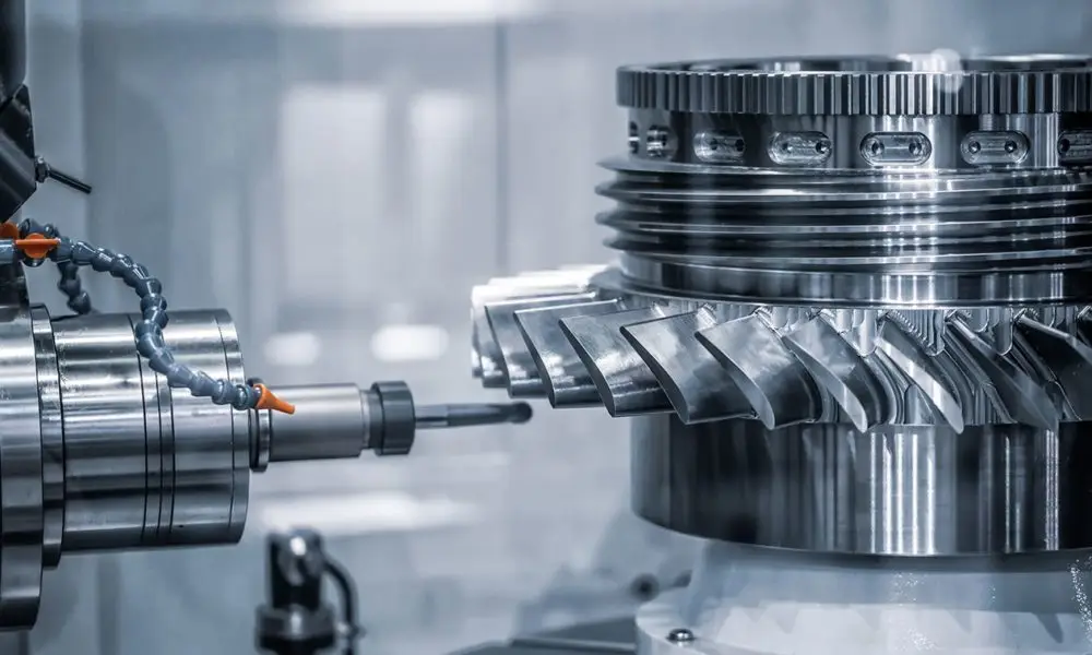
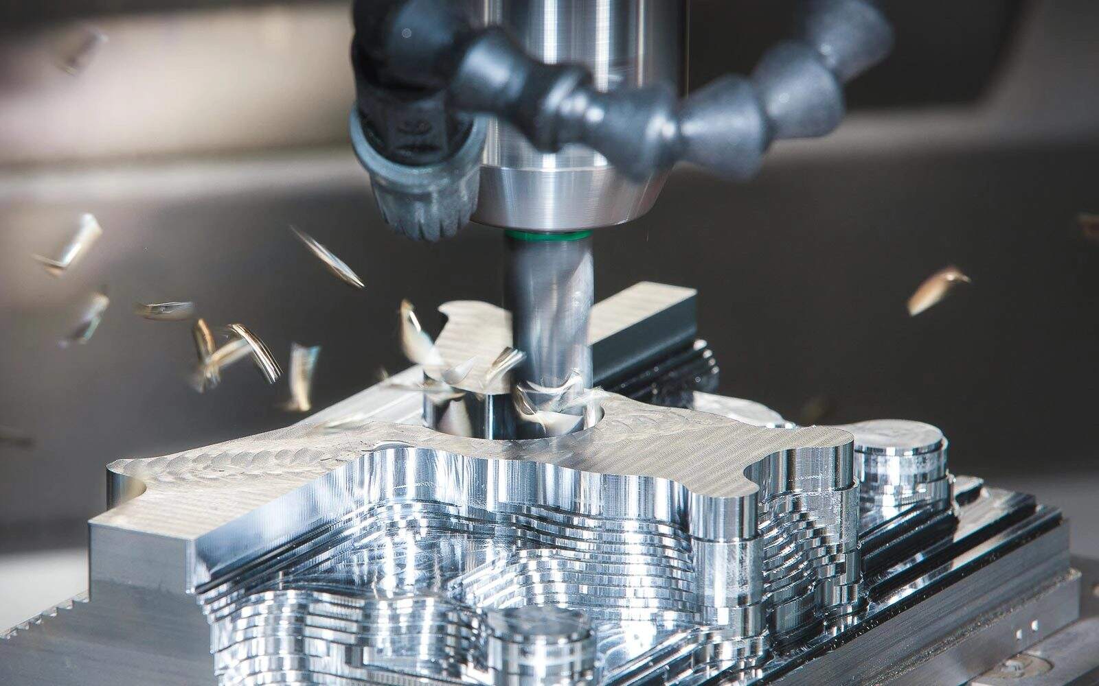
So how does a solid block of metal become a complex, precisely dimensioned cnc part? The journey begins long before any cutting occurs. Engineers first create a detailed 3D model using Computer-Aided Design (CAD) software. This digital blueprint captures every dimension, angle, and feature the finished component requires.
Next comes Computer-Aided Manufacturing (CAM) programming. Specialized software translates the CAD model into toolpaths, essentially choreographing every movement the cutting tools will make. The result? G-code, the universal language that tells the machine exactly where to move, how fast to spin, and how deep to cut.
Once the G-code reaches the machine controller, computer numerical control takes over. The system coordinates multiple axes of movement simultaneously, guiding cutting tools with micrometer-level precision. What once required master machinists working for hours now happens automatically, with consistency that human hands simply cannot match.
The Subtractive Manufacturing Advantage
Unlike 3D printing, which builds parts layer by layer, CNC machining removes material from a solid workpiece. This subtractive approach offers distinct advantages that make these cnc machine components indispensable across industries.
You'll notice that machined components consistently deliver properties that other manufacturing methods struggle to achieve:
- Dimensional accuracy: Tolerances as tight as ±0.001" are routinely achievable, ensuring parts fit and function exactly as designed
- Repeatability: Whether producing 10 parts or 10,000, each component matches the original specifications identically
- Material versatility: From soft aluminum to hardened tool steel, titanium to engineering plastics, the process handles virtually any machinable material
- Complex geometry capability: Multi-axis machines create intricate features, undercuts, and compound curves impossible with conventional methods
These characteristics explain why engineers specify machined components when precision matters. The parts of a cnc machine work in concert to deliver this precision, but the real value lies in what they produce: components that meet exact specifications, every single time.
With this foundation in place, you're ready to explore how different machining processes create specific component types, and how material selection influences everything from performance to cost.
Five Core CNC Machining Processes and the Parts They Produce
Now that you understand what defines cnc machined components, a natural question arises: which machining process creates which type of part? The answer depends entirely on your component's geometry, material, and precision requirements. Each process excels at producing specific shapes, and knowing when to apply each method can mean the difference between cost-effective production and expensive delays.
Understanding how a cnc machine works starts with recognizing that different operations suit different component geometries. Cylindrical parts demand different approaches than prismatic ones. Intricate details require different tools than simple flat surfaces. Let's break down the five core processes and the components each produces best.
Milling Operations and Their Component Outputs
CNC milling keeps the workpiece stationary while a rotating cutting tool removes material, layer by layer. This approach makes milling ideal for cnc milling parts with flat surfaces, pockets, slots, and complex three-dimensional contours. Think of engine housings, mounting brackets, mold cavities, and aerospace structural components.
The key components of cnc milling machine setups include the spindle, worktable, and multi-axis control system. These parts of a cnc mill work together to position the cutting tool precisely relative to the workpiece. But when should you choose 3-axis versus 5-axis milling?
3-axis milling moves the tool along X, Y, and Z linear axes while the workpiece stays fixed. This configuration handles straightforward geometries efficiently: flat surfaces, simple contours, and basic drilling operations. It's cost-effective and accessible, making it perfect for brackets, plates, and components without complex angular features.
5-axis milling adds two rotational axes, allowing the tool or workpiece to tilt and rotate. According to YCM Alliance, this capability eliminates multiple setups and enables machining of intricate geometries in a single operation. Turbine blades, impellers, and aerospace structural components with compound curves benefit significantly from 5-axis technology.
When does 5-axis justify its higher cost? Consider these scenarios:
- Parts requiring undercuts or angled features inaccessible from above
- Complex organic shapes demanding continuous tool contact
- Components where multiple setups would introduce cumulative tolerance errors
- High-value parts where superior surface finish reduces secondary operations
Turning Centers for Rotational Parts
CNC turning flips the milling approach: the workpiece rotates while a stationary tool removes material. This method excels at producing cylindrical cnc milling components and rotational parts with exceptional efficiency.
Turning centers produce shafts, bushings, pins, rollers, and any component with rotational symmetry. The process is faster than milling for round parts because the spinning workpiece continuously presents new material to the cutting edge. Aerospace landing gear components, automotive axle shafts, and hydraulic cylinder rods all emerge from turning operations.
Modern CNC lathes often include live tooling, adding milling capability to the turning process. This hybrid approach machines holes, slots, and flats on cylindrical parts without requiring a separate milling setup.
Drilling, Boring, and Reaming for Precision Holes
Hole-making operations form a distinct category of cnc milling machine parts production. Each process serves a specific purpose in the hole-creation sequence:
- Drilling creates the initial hole quickly and cost-effectively. Standard twist drills work across most materials, though internal wall surfaces remain relatively rough.
- Boring enlarges and aligns existing holes using a single-point cutting tool. This operation corrects positional errors and improves cylindricity for precision fits.
- Reaming provides the final touch, achieving specific diameters with mirror-like surface finishes. Critical tolerance holes in hydraulic valves and precision assemblies rely on reaming for exact dimensions.
Grinding for Superior Surface Finish
When surface finish requirements exceed what milling or turning can achieve, grinding steps in. This abrasive process removes tiny amounts of material to produce exceptionally smooth surfaces and tight tolerances.
Grinding proves essential for hardened components that would destroy conventional cutting tools. Bearing races, precision shafts, and gauge blocks all require grinding to meet their stringent specifications. According to University of Florida engineering data, surface finish requirements directly impact production time exponentially, so specify grinding only where functionally necessary.
EDM for Hardened Materials and Intricate Details
Electrical Discharge Machining (EDM) uses controlled electrical sparks to erode material, making it ideal for components that resist conventional cutting. Hardened tool steel dies, intricate mold cavities, and delicate medical components benefit from EDM's ability to machine without mechanical contact.
Wire EDM cuts complex profiles through thick materials with excellent accuracy, producing components like stamping dies and aerospace turbine disc slots. Sinker EDM creates three-dimensional cavities by plunging shaped electrodes into the workpiece.
| Process Type | Best For (Component Types) | Typical Tolerances | Surface Finish Capability (Ra) |
|---|---|---|---|
| CNC Milling (3-axis) | Flat surfaces, pockets, brackets, plates | ±0.005" standard, ±0.001" precision | 63-125 µin (1.6-3.2 µm) |
| CNC Milling (5-axis) | Turbine blades, impellers, complex contours | ±0.001" or tighter | 32-63 µin (0.8-1.6 µm) |
| CNC Turning | Shafts, bushings, pins, cylindrical parts | ±0.002" standard, ±0.0005" precision | 32-125 µin (0.8-3.2 µm) |
| Drilling/Boring/Reaming | Precision holes, bores, aligned features | ±0.001" (reaming) | 16-63 µin (0.4-1.6 µm) |
| Grinding | Hardened parts, bearing surfaces, gauge blocks | ±0.0002" achievable | 4-32 µin (0.1-0.8 µm) |
| EDM | Hardened dies, mold cavities, intricate details | ±0.0005" typical | 8-125 µin (0.2-3.2 µm) |
Selecting the right process comes down to matching your component's geometry, material, and precision requirements to each method's strengths. Cylindrical parts go to turning. Complex prismatic shapes go to milling. Hardened materials may require grinding or EDM. Often, a single component passes through multiple processes, combining their individual capabilities to achieve the finished specification.
With process selection understood, the next critical decision involves choosing the right material for your application, a choice that directly impacts machinability, performance, and cost.
Material Selection Guide for Precision Machined Parts
You've selected the right machining process for your component's geometry. Now comes an equally critical decision: which material should that machine cut? The material you choose affects everything from how fast your machined part can be produced to how long it will survive in service. Get this wrong, and you'll face excessive tool wear, blown budgets, or components that fail prematurely.
Material selection for cnc machined components isn't simply about picking the strongest or cheapest option. It's about matching material properties to your specific application requirements while considering machinability, cost, and environmental factors. Let's break down how to make this decision systematically.
Matching Materials to Application Requirements
Before comparing specific alloys, step back and define what your component actually needs to accomplish. According to HPPI's material selection guide, the process should start with evaluating functionality, strength, hardness, and environmental exposure before creating a shortlist of candidate materials.
Ask yourself these questions:
- What mechanical loads will this part experience? (tension, compression, fatigue, impact)
- What temperatures must it withstand during operation?
- Will it face corrosive environments, chemicals, or moisture?
- Does weight matter for this application?
- Are there electrical conductivity or insulation requirements?
- What surface finish or appearance does the end-use demand?
Your answers narrow the field considerably. High-stress structural parts demand steel or titanium. Lightweight aerospace components point toward aluminum or titanium. Corrosive environments call for stainless steel or certain plastics. Electrical applications may require brass or copper.
Machinability Ratings Explained
Here's something that surprises many engineers: the "best" material for your application might not be the most cost-effective to machine. Machinability ratings quantify how easily a material can be cut, and they directly impact production time, tool wear, and ultimately your per-part cost.
Machinability depends on several factors working together:
- Hardness: Harder materials require slower cutting speeds and cause faster tool wear
- Thermal conductivity: Materials that conduct heat poorly trap it at the cutting edge, accelerating tool degradation
- Chip formation: Some materials form long, stringy chips that tangle; others break cleanly
- Work hardening: Certain alloys harden as they're cut, making each subsequent pass more difficult
Free-machining brass (C360) rates among the easiest metals to cut, while titanium and some stainless grades challenge even experienced machinists. When production volume is high, choosing a more machinable grade within your material family can significantly reduce costs without sacrificing performance.
Metal Machined Parts: Your Primary Options
Metals dominate precision machining because they offer unmatched combinations of strength, durability, and dimensional stability. Let's examine each major category.
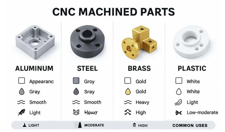
Aluminum Alloys deliver the best strength-to-weight ratio among common machined metal parts. Two grades handle the majority of applications:
- 6061: The workhorse alloy. Good strength, excellent corrosion resistance, and outstanding machinability. Perfect for structural brackets, housings, and general-purpose components.
- 7075: Significantly stronger than 6061, approaching some steels. Aerospace structures, high-stress fixtures, and performance automotive parts rely on this grade. Slightly more challenging to machine.
Carbon and Alloy Steels provide superior strength when weight isn't the primary concern. Cnc steel parts span applications from automotive drivetrain components to industrial machinery. According to Solutions Manufacturing, common grades include C1018 for general machining, C1045 for higher strength, and 4140 alloy steel when heat treatment is required for maximum hardness.
Stainless Steel adds corrosion resistance to steel's strength. Grade 303 machines easily due to added sulfur. Grade 304 offers better corrosion resistance for food and medical equipment. Grade 316 provides superior chemical resistance for marine and pharmaceutical applications.
Titanium combines low weight with exceptional strength and biocompatibility. Aerospace structural components, medical implants, and high-performance sporting goods justify titanium's premium cost. However, its poor thermal conductivity and tendency to work-harden make it one of the most challenging materials to machine economically.
Brass excels in electrical components, plumbing fittings, and decorative hardware. C360 (free-machining brass) cuts faster than almost any other metal, producing smooth surfaces with minimal tool wear. When your machine and parts need to cycle quickly through high volumes, brass delivers.
Engineering Plastics: When Metal Isn't the Answer
Sometimes the best material isn't a metal at all. Engineering plastics offer unique advantages for specific applications:
- Delrin (POM/Acetal): Low friction, excellent dimensional stability, and outstanding machinability. Gears, bushings, and precision mechanical parts of machines benefit from Delrin's self-lubricating properties.
- PEEK: The high-performance choice, withstanding temperatures up to 250°C continuously. Medical implants, aerospace components, and chemical processing equipment use PEEK when biocompatibility or extreme chemical resistance is required.
- Nylon: Good wear resistance and impact strength at low cost. However, it absorbs moisture and can swell, requiring design allowances for dimensional changes.
According to CNCMachines.com, plastics typically achieve tolerances of ±0.002" to ±0.010", wider than metals due to their thermal sensitivity and potential for warping during machining.
| Material Category | Common Grades | Key Properties | Typical Applications | Relative Cost |
|---|---|---|---|---|
| Aluminum | 6061, 7075, 2024 | Lightweight, corrosion resistant, excellent machinability | Aerospace structures, electronics housings, automotive brackets | Low-Medium |
| Carbon Steel | C1018, C1045, C12L14 | High strength, good machinability, heat treatable | Shafts, gears, structural components, fixtures | Low |
| Alloy Steel | 4140, 4340, 8620 | Superior strength, hardness after heat treatment | Drivetrain components, high-stress fasteners, tooling | Medium |
| Stainless Steel | 303, 304, 316 | Corrosion resistant, hygienic, durable | Medical devices, food equipment, marine hardware | Medium-High |
| Titanium | Grade 2, Grade 5 (Ti-6Al-4V) | High strength-to-weight, biocompatible, corrosion resistant | Aerospace components, medical implants, performance parts | High |
| Brass | C360, C260 | Excellent machinability, electrical conductivity, corrosion resistant | Electrical connectors, valves, plumbing fittings | Medium |
| Delrin (POM) | Homopolymer, Copolymer | Low friction, dimensionally stable, self-lubricating | Gears, bushings, precision mechanical parts | Low-Medium |
| PEEK | Unfilled, Glass-filled, Carbon-filled | High temperature resistance, chemical inert, biocompatible | Medical implants, aerospace seals, chemical equipment | Very High |
Making the Final Material Decision
With your requirements defined and material options understood, how do you make the final call? Consider these decision factors in order:
- Functional requirements first: Eliminate any materials that can't meet mechanical, thermal, or environmental demands
- Machinability second: Among qualified materials, favor those with better machinability ratings to reduce production costs
- Surface finish compatibility: Ensure your chosen material accepts any required plating, anodizing, or coating
- Budget constraints last: Only after confirming functional suitability should cost become the deciding factor
Sometimes you'll need to compromise. A slightly more expensive material with better machinability may actually cost less per finished part than a cheaper raw material that wears out tools quickly. Evaluate total production cost, not just material price.
With your material selected, the next step involves specifying exactly how precise your machined part needs to be, and understanding how those tolerance requirements impact both quality and cost.
Tolerance Specifications and Surface Finish Standards
You've chosen your material. Now comes a question that directly impacts both your component's performance and your budget: how precise does this machine part need to be? Specifying tolerances incorrectly leads to two costly outcomes. Too loose, and parts won't fit or function properly. Too tight, and you'll pay exponentially more for precision you don't actually need.
Understanding tolerance classes and surface finish specifications separates engineers who optimize costs from those who over-engineer everything. Let's decode these critical specifications so you can make informed decisions for your precision cnc machined components.
Understanding Tolerance Classes and Their Applications
Tolerances define the acceptable variation from a part's intended dimensions. According to Dadesin's tolerance guide, no manufacturing process produces parts with absolute perfection, so specifying tolerances ensures components fit together and function as designed.
CNC machining capabilities fall into three general tolerance classes:
Standard tolerances (±0.005" / ±0.127mm) represent the baseline for general machining operations. Most CNC mills and lathes achieve this level without special setup or extended cycle times. Non-critical dimensions, clearance holes, and surfaces without mating requirements typically fall here. This tolerance class offers the fastest production and lowest cost per part machine.
Precision tolerances (±0.001" / ±0.025mm) require more careful machining: slower feeds, finer finishing passes, and possibly temperature-controlled environments. Press fits, bearing bores, and close-tolerance assemblies demand this level. Expect cycle times to increase 10-30% compared to standard tolerances.
Ultra-precision tolerances (±0.0005" / ±0.013mm or tighter) push the limits of conventional CNC equipment. Achieving these specifications often requires grinding, lapping, or specialized machinery. Optical components, precision gauge blocks, and aerospace-critical features may justify the significant cost premium.
The relationship between tolerance and cost isn't linear. As tolerances tighten, costs escalate exponentially:
Moving from ±0.005" to ±0.001" might increase machining costs by 20-30%. But tightening further to ±0.0002" can double or triple production costs due to specialized equipment, extended cycle times, and higher scrap rates.
Different tolerance types control different characteristics of cnc precision machined components:
- Dimensional tolerances: Control linear measurements like lengths, diameters, and depths
- Geometric tolerances (GD&T): Control form, orientation, and position—including flatness, perpendicularity, and concentricity
- Bilateral tolerances: Allow variation in both directions (±0.002")
- Unilateral tolerances: Allow variation in only one direction (+0.002"/-0.000")
According to industry standards like ISO 2768, tolerance classes range from Fine (f) for high-precision parts to Very Coarse (v) for rough machining. Specifying the appropriate ISO class simplifies drawings and communicates expectations clearly to manufacturers.
Surface Finish Specifications Decoded
Surface finish describes how smooth or rough a machined surface appears at the microscopic level. The most common measurement is Ra (Roughness Average), which represents the average deviation from an ideal flat surface. According to The Supplier's surface finish guide, Ra values are expressed in micrometers (µm) or microinches (µin), with lower numbers indicating smoother surfaces.
Typical CNC milling achieves Ra 1.6-3.2 µm (63-125 µin) as-machined with a fine finishing pass. This standard finish works for most functional surfaces. But some applications demand smoother finishes, while others accept rougher surfaces without issue.
Different industries have distinct surface finish requirements:
- Aerospace: Sealing surfaces require Ra ≤0.8 µm; structural faces accept Ra 1.6-3.2 µm; hidden surfaces permit Ra 3.2-6.3 µm
- Medical devices: Implant surfaces demand Ra ≤0.4 µm for biocompatibility; instrument handles may accept Ra 1.6 µm
- Automotive: Gasket mating surfaces need Ra 0.8-1.6 µm; decorative trim requires consistent cosmetic finishes
- Hydraulic systems: Cylinder bores require Ra ≤0.4 µm for seal performance; external housings accept as-machined finishes
- Consumer electronics: Visible surfaces demand cosmetic finishes via bead-blast and anodize; internal structures accept standard machining
Achieving smoother finishes increases cost through additional machining passes, specialized tooling, or secondary operations like grinding and polishing. The Supplier notes that polished or lapped finishes (Ra ≤0.2 µm) can add 50-100% to machining costs and extend lead times by 1-2 weeks.
Surface Finishing Options for Complex Machined Parts
Beyond the as-machined condition, secondary finishing processes enhance appearance, corrosion resistance, and wear properties. Each finishing method interacts differently with base surface roughness and part dimensions.
Anodizing builds a protective oxide layer on aluminum surfaces. Type II (clear or dyed) anodizing adds 5-15 µm thickness, with approximately half growing inward and half outward. This dimensional change matters for press fits and precision bores. Bead-blasted surfaces before anodizing produce a premium matte appearance that hides tool marks effectively.
Plating deposits metallic coatings that can level minor surface imperfections. Electroless nickel provides uniform coverage even in recesses, adding 5-25 µm while improving wear resistance. Zinc plating offers sacrificial corrosion protection for steel components. Bright nickel-chrome stacks deliver highly reflective decorative finishes but amplify any flaws in the underlying surface.
Powder coating applies a durable polymer finish for cosmetic and protective purposes. The electrostatic application and heat curing process adds 50-100 µm thickness, requiring careful consideration for dimensional fits.
Passivation chemically treats stainless steel to enhance its natural corrosion resistance without adding measurable thickness. This process removes free iron from the surface and strengthens the chromium oxide layer.
Specifying Tolerances and Finishes Strategically
The key to cost-effective cnc machining components lies in applying tight specifications only where function demands them. Consider these strategies:
- Identify critical features: Mating surfaces, press fits, and sealing zones need tight tolerances; hidden faces don't
- Use standard tolerances as the default: Only call out tighter specifications where analysis proves they're necessary
- Limit surface finish callouts: Specify low Ra only on functional zones like gasket lands and bearing surfaces
- Consider finishing sequences: Some coatings require specific base surface conditions; plan the sequence upfront
- Account for coating thickness: Adjust pre-finish dimensions to achieve final specifications after plating or anodizing
When preparing drawings, use proper tolerance symbols per ISO 1302 or ASME Y14.5 standards. State measurement methods and sampling frequency to ensure suppliers inspect consistently. For example: "Ra 1.6 µm max on marked sealing bands; measure per ISO 4288; verify 1 per 50 pieces."
With tolerance and finish specifications mastered, you're ready to see how these precision requirements translate into real-world applications across different industries—each with unique demands for their cnc machined components.
Industry Applications from Automotive to Aerospace
So what can a CNC machine do in practice? The answer spans nearly every major manufacturing sector, each with distinct demands for precision, durability, and material performance. Understanding how different industries apply cnc machined components helps you connect the material selection and tolerance principles covered earlier to real-world production scenarios.
Each industry places unique requirements on its machined parts. Automotive components must survive constant vibration and extreme temperature cycles. Aerospace parts demand weight optimization without sacrificing strength. Medical devices require biocompatibility and sterilization resistance. Let's examine how these demands translate into specific cnc machine products across four major sectors.
Automotive Drivetrain and Chassis Components
The automotive industry relies heavily on CNC machining to produce thousands of precision components per vehicle. According to Motor City Metal Fab, modern vehicles contain thousands of precision-machined components requiring exact specifications for proper function and safety. From powertrain to suspension, cnc machined automotive components must withstand extreme temperatures, constant vibration, and years of continuous use.
Key automotive applications include:
- Engine components: Cylinder heads with complex combustion chambers and cooling passages; crankshafts with journal surfaces ground to microinch finishes; fuel injector bodies requiring microscopic precision for proper fuel atomization
- Transmission parts: Gear housings machined to hold bearing fits within ±0.001"; helical and bevel gears produced on 5-axis machines; valve bodies with intricate hydraulic passages
- Brake system components: Rotors machined to thickness variations measured in ten-thousandths of an inch; caliper bodies with complex internal passages; master cylinder bores requiring mirror finishes for seal performance
- Suspension and steering: Control arms machined from forged aluminum billets; knuckles requiring multiple operations in single setups; rack housings with smooth bearing surfaces and precise mounting features
The shift toward electric vehicles creates new cnc machining part demands. Battery enclosures require lightweight aluminum alloys machined for proper sealing and thermal management. Motor housings demand exceptional roundness and concentricity for efficient operation. Power electronics housings combine thermal management fins with electromagnetic shielding requirements.
Quality standards in automotive manufacturing exceed most other industries. According to Motor City Metal Fab, modern CNC machines routinely achieve tolerances of ±0.0002 inches for critical features like bearing journals and valve seats. Statistical process control (SPC) monitors production continuously, identifying trends before parts drift out of specification.
Aerospace Structural and Engine Parts
Aerospace represents the most demanding application for manufacturing machine parts. Components must perform flawlessly while minimizing weight—every gram matters when fuel efficiency drives operating costs. The materials covered earlier, particularly titanium and aluminum alloys 7075 and 2024, find their primary home in aerospace applications.
According to Advantage Metal Products, aerospace engine components include:
- Turbine blades and vanes: Complex airfoil geometries machined from nickel-based superalloys; 5-axis operations creating compound curves impossible with conventional methods
- Compressor components: Titanium blades and vanes requiring tight tolerances for efficient airflow; engine casings balancing strength with minimum weight
- Combustion chamber liners: Heat-resistant alloys machined with specialized techniques to handle extreme operating temperatures
- Bearings and shafts: Precision ground surfaces achieving microinch finishes for reduced friction and extended service life
Structural aerospace components present different challenges:
- Wing ribs and spars: Large aluminum components with complex pocket geometries removing up to 90% of raw material; thin walls requiring careful machining strategies to prevent distortion
- Landing gear components: High-strength steel and titanium parts withstanding enormous impact loads; critical tolerance features for proper assembly and function
- Structural brackets: Load-bearing connections machined from titanium or high-strength aluminum; weight optimization through topology-influenced designs
- Fuselage frames: Large-scale components requiring multi-axis machining for complex contours and attachment features
Aerospace manufacturing demands AS9100 certification for quality management systems. Material traceability, first article inspection, and comprehensive documentation ensure every component meets stringent requirements. The tolerance specifications covered earlier—particularly ultra-precision levels—find frequent application in aerospace cnc examples where safety depends on absolute dimensional accuracy.
Medical Devices and Implant Components
Medical applications represent a unique intersection of precision requirements and material constraints. According to Makerverse, orthopedic implants must align perfectly with patient anatomy, and slight dimensional deviations could lead to discomfort, malfunction, or surgical failure.
Biocompatibility drives material selection in medical CNC machining. Titanium dominates implant production due to its strength, low weight, and acceptance by human tissue. Cobalt-chrome alloys serve dental and orthopedic applications requiring wear resistance. PEEK provides alternatives where metal isn't suitable.
Critical medical applications include:
- Surgical instruments: Scalpels, forceps, retractors, and bone drills machined from stainless steel to exact dimensions with sharp, durable edges; instruments must withstand repeated sterilization cycles
- Orthopedic implants: Hip joints and knee replacements requiring precise geometries for proper anatomical fit; spinal rods, screws, and plates machined to exacting tolerances
- Dental implants: Titanium fixtures with micro-scale threads and surface textures promoting bone integration; abutments requiring precise mating surfaces
- Diagnostic equipment: MRI machine housings, CT scanner components, and ultrasound device brackets machined to enable accurate diagnostic results
Surface finish requirements in medical manufacturing often exceed other industries. Implant surfaces demand Ra ≤0.4 µm for biocompatibility, while visible instrument surfaces require consistent cosmetic finishes. ISO 13485 certification governs quality management systems for medical device manufacturing.
Heavy Equipment and Industrial Machinery
Heavy equipment applications showcase CNC machining's capability for large-scale, high-strength components. Construction equipment, mining machinery, and agricultural implements rely on machined parts that withstand punishing operating conditions.
Key heavy equipment applications include:
- Hydraulic manifolds: Complex internal passages drilled and milled to precise specifications; cross-holes requiring accurate positioning for proper flow control
- Gear housings: Large cast or fabricated components finish-machined for bearing fits and seal surfaces; multiple operations completed in single setups to maintain alignment
- Structural pins and bushings: High-strength steel components machined to withstand enormous loads; hardened surfaces requiring grinding for final dimensions
- Cylinder components: Hydraulic cylinder barrels honed to mirror finishes for seal performance; rod ends machined for precise thread engagement
Heavy equipment components often start as castings or forgings, with CNC machining providing final dimensions on critical features. This hybrid approach combines the cost-effectiveness of near-net-shape processes with the precision of CNC finishing operations.
Connecting Industry Requirements to Earlier Specifications
Notice how each industry's demands connect directly to the material selection and tolerance principles covered earlier:
- Automotive: Steel alloys (4140, 4340) for drivetrain strength; aluminum (6061) for weight-sensitive components; precision tolerances (±0.001") for bearing fits and hydraulic passages
- Aerospace: Titanium and high-strength aluminum for weight optimization; nickel superalloys for extreme temperatures; ultra-precision tolerances for flight-critical features
- Medical: Biocompatible titanium and PEEK; mirror surface finishes for implants; precision tolerances for anatomical fit
- Heavy equipment: High-strength steels for load-bearing applications; standard to precision tolerances based on functional requirements
Understanding these industry-specific requirements helps you specify appropriate materials, tolerances, and finishes for your particular application. But specifications alone don't guarantee quality—that requires robust inspection processes and recognized certifications, which we'll examine next.
Quality Control and Industry Certifications Explained
You've specified the right material, defined tolerances, and identified your industry's requirements. But here's a critical question: how do you know the finished cnc machined components actually meet those specifications? One successful part doesn't guarantee the next will be identical. Quality control bridges the gap between design intent and production reality.
Understanding inspection processes and industry certifications helps you evaluate manufacturing partners and ensures your components arrive ready for assembly—not the reject bin. Let's decode the quality systems that separate reliable suppliers from those that ship problems.
First Article Inspection and Production Validation
Before committing to full production, manufacturers perform First Article Inspection (FAI) on initial samples. This comprehensive verification confirms that the production process can consistently produce parts meeting all specifications. According to CNCFirst, FAI establishes the stable baseline that all subsequent quality monitoring depends upon.
A thorough FAI examines every dimension, tolerance, and surface finish callout on your drawing. Inspectors verify:
- Critical dimensions: Every specified measurement checked against drawing requirements
- Geometric tolerances: Flatness, perpendicularity, concentricity, and position verified per GD&T callouts
- Surface finish: Ra measurements on specified surfaces using profilometers
- Material certification: Mill test reports confirming alloy composition matches specifications
- Visual inspection: Surface defects, burrs, and cosmetic appearance evaluated
But here's what many buyers overlook: FAI alone isn't enough. According to manufacturing quality experts, dimensional deviations can slowly accumulate during mass production. One successful part does not guarantee the next will be good. That's why ongoing inspection processes matter just as much as initial validation.
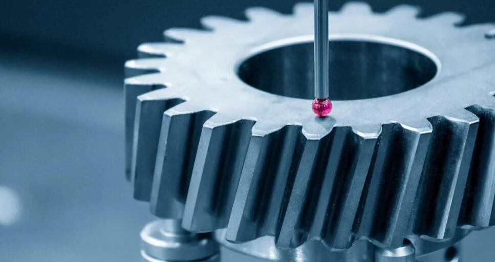
CMM Inspection: The Precision Measurement Standard
Coordinate Measuring Machines (CMMs) represent the gold standard for dimensional verification of precision parts. These sophisticated systems use probes to detect surface points along X, Y, and Z axes, recording coordinates with remarkable accuracy. According to Kesu Group, modern CMMs achieve accuracies of 0.5 microns—far exceeding what manual measurement tools can provide.
CMM inspection serves multiple purposes throughout production:
- FAI verification: Comprehensive dimensional reports for initial samples
- In-process checks: Periodic measurements during production runs to detect drift
- Final inspection: Acceptance verification before shipment
- Reverse engineering: Capturing as-built dimensions for documentation
The CMM process compares measured coordinates against your original CAD model, identifying any deviations from design specifications. This capability proves especially valuable for complex geometries where manual measurement would be impractical or inaccurate. Components of a cnc machine produce intricate features that only CMM inspection can properly verify.
Beyond CMMs, quality labs employ complementary inspection tools: calipers and micrometers for quick checks, optical comparators for profile verification, surface roughness testers for finish measurements, and hardness testers for material verification.
Statistical Process Control: Catching Problems Before They Grow
Imagine producing 100 parts and discovering 3 are out of tolerance during final inspection. The other 97 might also hide defects. This reactive approach wastes material, time, and money. Statistical Process Control (SPC) takes a fundamentally different approach.
According to CNCFirst's SPC analysis, this quality management tool uses statistical methods to monitor and analyze the production process continuously. By collecting and analyzing production data in real-time, SPC detects and corrects deviations early—before defective parts accumulate.
Here's how SPC works in practice: operators measure key dimensions at regular intervals—perhaps the 5th, 10th, and every 25th piece. These measurements plot on control charts showing the natural variation range. If a dimension begins drifting toward the tolerance limit, action happens immediately: tool compensation adjusts, cutting edges get replaced, or coolant conditions are corrected.
The value of SPC becomes clear in real production scenarios. CNCFirst documented a case where a medical device customer's previous supplier achieved only 92% yield. By implementing SPC, they discovered that from the 85th part onward, a key bore diameter slowly drifted upward during tool life. Replacing the cutting edge at the 80th piece and adjusting offsets resulted in 99.7% yield—a dramatic improvement that reduced scrap and rework costs significantly.
SPC catches machining errors from multiple sources: tool wear during cutting operations, thermal expansion from friction and ambient temperature changes, fixture loosening over time, and material hardness variations. Each factor alone looks minor, but together they reduce yield. SPC turns these small variations into visible, controllable data.
Certifications That Matter for Your Industry
Quality certifications demonstrate a manufacturer's commitment to systematic quality management. According to Hartford Technologies, having applicable certifications is crucial for buyers considering whether an organization is fit to do business with—particularly in automotive and medical industries.
Different industries require different certifications based on their unique quality demands. Understanding what each certification requires helps you evaluate whether a supplier's cnc machining capabilities match your application needs.
| Certification | Industry Focus | Key Requirements | Why It Matters |
|---|---|---|---|
| ISO 9001 | General manufacturing (all industries) | Quality management system documentation; customer focus; continuous improvement processes; internal audits | Establishes baseline quality management; demonstrates systematic approach to meeting customer requirements; recognized globally |
| IATF 16949 | Automotive | All ISO 9001 requirements plus: APQP/PPAP processes; customer-specific requirements; defect prevention emphasis; supply chain management | Required by major automakers; ensures compliance with stringent automotive regulations; emphasizes zero-defect mentality |
| AS9100 | Aerospace and defense | ISO 9001 foundation plus: configuration management; risk management; special process controls; full material traceability | Mandatory for aerospace supply chains; addresses safety-critical requirements; ensures complete documentation for parts of cnc machines and finished components |
| ISO 13485 | Medical devices | Design controls; risk management throughout product lifecycle; sterile manufacturing controls; regulatory compliance documentation | Required for medical device production; prioritizes patient safety; aligns with FDA and EU regulatory requirements |
What do these certifications actually mean for your components? They ensure documented procedures govern every production step. They require calibrated measurement equipment with traceable standards. They mandate trained personnel following verified processes. They demand corrective action systems that prevent recurring problems.
For parts of cnc machines and the components they produce, certifications provide traceability—the ability to track any part back to its raw material, machining operations, inspection records, and operator. When problems occur, this traceability enables rapid root cause analysis and targeted corrective action.
Connecting Quality Systems to Sourcing Decisions
Quality control isn't just a manufacturing concern—it directly impacts your sourcing strategy. When evaluating potential suppliers, consider these quality-related factors:
- Certification alignment: Does the supplier hold certifications relevant to your industry?
- Inspection capabilities: Do they have CMM equipment appropriate for your tolerance requirements?
- SPC implementation: Is statistical process control standard practice or an afterthought?
- Documentation practices: Can they provide inspection reports, material certifications, and traceability records?
- Corrective action history: How do they respond when quality issues arise?
Manufacturers who invest in robust quality systems typically deliver more consistent results and respond more effectively when problems occur. These investments also impact cost structures—which leads us to examine what actually drives cnc machining pricing and how design decisions influence your final component costs.
Cost Factors and Design Optimization Strategies
Here's a reality check: up to 80% of manufacturing cost gets locked in during the design phase. That means the decisions you make before machining begins—material choice, geometry complexity, tolerance specifications—determine most of what you'll pay for finished cnc machined products. Understanding these cost drivers transforms you from a passive buyer into someone who actively controls project economics.
The good news? Most cost-saving opportunities require design adjustments, not quality sacrifices. Let's break down exactly what drives CNC machining costs and how smart design decisions keep budgets in check.
What Drives CNC Machining Costs
According to RapidDirect's cost analysis, CNC part cost follows a straightforward formula:
Total Cost = Material Cost + (Machining Time × Machine Rate) + Setup Cost + Finishing Cost
Each element contributes differently depending on your specific project. Understanding these components helps you identify where optimization efforts will yield the greatest savings.
Material selection and waste: Raw material cost extends beyond the price per pound. Larger parts or designs forcing oversized stock increase both material use and scrap. According to Fathom Manufacturing, harder, more exotic materials increase tool wear and machining time significantly. A titanium cnc machine part might cost three times more than aluminum—not just because titanium costs more, but because it machines slower and consumes tooling faster.
Machining complexity and cycle time: This factor typically dominates total cost. Complex geometries require more toolpaths, slower cutting speeds, and frequent tool changes. Deep pockets, thin walls, and intricate features all extend machine time. According to RapidDirect, features that increase complexity include:
- Deep cavities requiring multiple depth passes with small-diameter tools
- Thin walls demanding light cuts to prevent deflection
- Tight internal corners forcing smaller end mills and slower feeds
- Undercuts requiring 5-axis machining or specialized tooling
- Multiple setups when features can't be accessed from one orientation
Tolerance requirements: The tolerance specifications covered earlier directly impact cost. Standard tolerances (±0.005") require no special measures. Precision tolerances (±0.001") demand slower feeds, finer finishing passes, and extended inspection time. Ultra-tight tolerances may require grinding operations that double or triple machining costs.
Quantity and setup amortization: Setup costs—CAM programming, fixturing, tool setup, and first-article verification—remain fixed regardless of how many parts you order. This creates dramatic per-unit cost differences based on quantity:
| Quantity | Setup Cost Per Part | Relative Unit Price |
|---|---|---|
| 1 piece | $300.00 | Highest |
| 10 pieces | $30.00 | High |
| 50 pieces | $6.00 | Moderate |
| 100 pieces | $3.00 | Lower |
| 500 pieces | $0.60 | Lowest practical |
This explains why prototypes cost significantly more per unit than production runs. The sweet spot for most machining components falls between 50-500 pieces, where setup costs distribute efficiently without overwhelming production capacity.
Secondary finishing operations: Post-processing adds cost based on surface area, complexity, and requirements. According to Fathom, secondary operations like deburring, heat treating, plating, and painting can significantly inflate total costs. Consider finishing requirements during design—could a different material eliminate the need for protective coating?
Optimizing Designs for Cost-Effective Production
Now that you understand what drives costs, here's how to minimize them without compromising functionality. According to Elimold's DFM analysis, Design for Manufacturing principles ensure parts can be reliably produced in the most efficient, economical way.
Apply these cost optimization strategies during your design phase:
- Simplify geometry: Eliminate features that don't serve functional purposes. Each additional pocket, contour, or detail adds machining time.
- Increase internal radii: Larger corner radii allow bigger end mills that cut faster. Specify the largest radius your design permits.
- Design for standard tooling: Use common drill sizes, standard thread pitches, and conventional depths. Custom tools add cost and lead time.
- Avoid undercuts: Features requiring 5-axis machining or specialized cutters increase costs dramatically. Redesign as two simpler components when possible.
- Relax unnecessary tolerances: Apply tight tolerances only to functional features. General tolerances (ISO 2768-m) work fine for most dimensions.
- Consider material machinability: Among materials meeting your requirements, choose grades that machine easily. Free-machining brass cuts faster than standard brass; 6061 aluminum machines more economically than 7075.
- Design around standard stock sizes: Parts fitting common bar or plate dimensions minimize material waste and raw material cost.
Lead time requirements also affect pricing significantly. Rush orders command premium rates because they disrupt production schedules and may require overtime labor. Planning ahead and allowing standard lead times—typically 2-3 weeks for cnc machining products—keeps costs predictable.
For large part cnc machining, additional considerations apply. Oversized components may require specialized equipment with higher hourly rates. Material handling, fixture design, and inspection all become more complex as part size increases.
Prototype to Production: Managing the Transition
The machined parts needed for prototyping differ fundamentally from production requirements. Prototype quantities rarely exceed 5-10 pieces, making setup costs the dominant factor. At this stage, focus on validating your design rather than optimizing manufacturing cost.
Once designs stabilize, production planning changes the equation. Quantities of 50-500 pieces unlock significant per-unit savings as setup costs amortize across more parts. Tooling investments that make no sense for prototypes become economical at production volumes.
Smart buyers leverage this progression strategically:
- Prototype phase: Accept higher per-unit costs; prioritize fast iteration and design validation
- Pre-production: Refine designs using DFM feedback; eliminate costly features before committing to volume
- Production: Lock specifications; optimize batch sizes for best unit economics
According to RapidDirect, automated DFM checking tools now flag manufacturability issues instantly—thin walls, deep holes, and features requiring 5-axis machining—helping engineers revise designs before ordering. This early feedback prevents expensive discoveries later in the process.
With cost factors understood, the question becomes: when does CNC machining make the most economic sense compared to alternative manufacturing methods? That comparison helps you select the right process for each project's unique requirements.
CNC Machining Versus Casting, Forging, and Additive Manufacturing
You've mastered what drives CNC machining costs. But here's the bigger question: should you even use CNC machining for your project? Sometimes the answer is no. Casting might deliver better economics for high volumes. Forging could provide superior strength. 3D printing might handle geometries that would break your tooling budget. Understanding when each manufacturing method excels helps you make decisions that optimize both quality and cost.
According to BDE Inc., selecting a production process requires understanding the technical foundation of each method. Let's compare these alternatives against cnc machined parts so you can identify the right approach for your specific requirements.
When CNC Machining Outperforms Alternatives
CNC machining delivers advantages that other processes struggle to match in certain scenarios. Understanding these strengths helps you recognize when machining is your best option—and when alternatives deserve consideration.
Material versatility stands unmatched. Unlike casting or 3D printing, which limit you to specific alloy families or feedstocks, CNC machining handles virtually any machinable material. Need a cnc part from exotic titanium alloy? Machining works. Require PEEK for chemical resistance? No problem. This flexibility proves invaluable when application requirements dictate unusual material specifications.
Precision exceeds other methods. According to Jiga's comparative analysis, CNC machining achieves tolerances as tight as ±0.01 mm on small features, with even tighter specifications possible at additional cost. Compare this to 3D printing's typical ±0.05–0.3 mm or casting's ±0.5 mm, and you'll understand why critical-fit components demand machining.
Surface finish arrives ready for use. Machined surfaces achieve Ra 0.4–1.6 µm directly from the cutting process. Additive manufacturing produces layer lines requiring extensive post-processing. Castings need grinding and polishing to approach similar quality. When cosmetic or functional surface requirements matter, cnc machining parts often skip secondary operations entirely.
Full isotropic material properties. Here's something many engineers overlook: 3D printed metal parts exhibit anisotropic properties—stronger in some directions than others. Cnc parts machined from solid stock retain the full strength characteristics of the parent material in all directions. For load-bearing applications, this difference matters enormously.
Choose CNC machining when your project requires:
- Tight tolerances below ±0.05 mm
- Smooth surface finishes without extensive post-processing
- Full mechanical properties in all loading directions
- Materials unavailable in casting alloys or 3D printing feedstocks
- Low-to-medium volumes where tooling investments don't amortize
- Rapid design iterations without waiting for mold modifications
Alternative Manufacturing Methods: When They Make Sense
Casting excels at high-volume production of complex shapes with internal cavities. According to BDE Inc., die casting uses pressure to force molten metal into molds, enabling excellent repeatability across thousands of parts. The tooling investment—often $10,000 to $100,000—only makes sense when spread across large quantities.
When does casting beat machining? Consider casting when:
- Production volumes exceed 1,000 pieces annually
- Complex internal geometries would require extensive machining
- Thin-walled structures would challenge conventional cutting
- Material waste from machining approaches 80% or more
However, cast parts typically require CNC finishing on critical surfaces—creating hybrid workflows where casting provides the near-net shape and machining adds precision.
Forging delivers superior mechanical properties for high-stress applications. The process aligns grain structure along load paths, creating parts stronger than equivalent machined components. Automotive connecting rods, aerospace structural fittings, and heavy equipment pins often start as forgings before CNC finishing operations add final dimensions.
The cnc tool path then removes minimal material from the forged blank, preserving the advantageous grain flow while achieving precise tolerances. This combination delivers both strength and accuracy.
3D printing (additive manufacturing) builds parts layer by layer, enabling geometries impossible with any subtractive process. According to Jiga, additive manufacturing excels at creating complex internal features like cooling channels, lattice structures for weight reduction, and organic shapes optimized through topology analysis.
Examples of cnc machining simply cannot replicate what additive manufacturing achieves in certain applications. Imagine a hydraulic manifold with flowing internal passages that minimize pressure drop—3D printing creates this directly, while machining would require multiple intersecting drilled holes with less optimal flow characteristics.
Choose 3D printing when:
- Internal channels or cavities are impossible to machine
- Prototype quantities (1-10 pieces) don't justify setup costs
- Lightweight lattice structures reduce weight without sacrificing strength
- Rapid design iteration matters more than per-part cost
- Part consolidation combines multiple components into single prints
Injection molding dominates high-volume plastic production. Once molds are built (typically $5,000-$50,000), per-part costs drop dramatically—sometimes to pennies. For plastic components needed in thousands or millions, injection molding beats CNC machining economically despite the tooling investment.
Comparing Manufacturing Methods: Decision Framework
This comparison table helps you evaluate which process fits your project requirements:
| Method | Best Volume Range | Typical Tolerances | Material Options | Lead Time |
|---|---|---|---|---|
| CNC Machining | 1-500 pieces (sweet spot: 10-200) | ±0.01-0.05 mm standard; ±0.005 mm precision | All machinable metals, plastics, composites | 1-3 weeks typical; days for rush orders |
| Die Casting | 1,000-1,000,000+ pieces | ±0.1-0.5 mm as-cast; tighter with machining | Aluminum, zinc, magnesium alloys | 8-16 weeks for tooling; days per production run |
| Investment Casting | 100-10,000 pieces | ±0.1-0.25 mm | Most castable alloys including steel, titanium | 4-8 weeks including pattern development |
| Forging | 500-100,000+ pieces | ±0.5-2 mm as-forged; finishing required | Steel, aluminum, titanium, copper alloys | 6-12 weeks for dies; ongoing production faster |
| Metal 3D Printing (DMLS/SLM) | 1-100 pieces | ±0.05-0.3 mm; post-machining often needed | Stainless steel, titanium, aluminum, Inconel | 1-3 weeks depending on complexity |
| Polymer 3D Printing (SLS/FDM) | 1-500 pieces | ±0.1-0.5 mm | Nylon, ABS, PEEK, TPU, various resins | Days to 2 weeks |
| Injection Molding | 5,000-10,000,000+ pieces | ±0.05-0.1 mm | Thermoplastics, thermosets, some composites | 4-12 weeks for tooling; hours per production run |
Hybrid Manufacturing Approaches
Here's what experienced manufacturing engineers know: the best solution often combines multiple processes. According to BDE Inc., hybrid manufacturing integration capitalizes on each method's strengths while reducing individual drawbacks.
Common hybrid workflows include:
Casting plus CNC finishing: Cast the complex shape economically, then machine critical interfaces to tight tolerances. Automotive engine blocks, pump housings, and gearbox cases follow this pattern. The casting handles 80% of material removal at low cost; machining adds precision where it matters.
Forging plus CNC machining: Forge for strength, machine for accuracy. Aerospace landing gear components, automotive crankshafts, and heavy equipment pins start as forgings. CNC operations create bearing journals, threaded features, and precision fits without compromising the forging's superior grain structure.
3D printing plus CNC finishing: Print complex geometries, then machine critical surfaces. Metal additive parts typically require post-processing anyway—support removal, stress relief, surface improvement. Adding CNC operations on functional interfaces costs little extra while dramatically improving dimensional accuracy.
According to Jiga, hybrid workflows combining additive processes for complex features with CNC machining for critical surfaces often deliver optimal results. The cnc tool removes minimal material from the printed blank, focusing only on surfaces requiring tight tolerances or smooth finishes.
Making the Right Process Decision
When evaluating manufacturing alternatives, work through these decision criteria in order:
- Define volume requirements: Low volumes favor CNC machining or 3D printing. High volumes shift economics toward casting, forging, or injection molding.
- Assess geometric complexity: Internal features and organic shapes point toward additive or casting. Prismatic geometries with accessible surfaces suit machining.
- Verify material requirements: Unusual alloys or high-performance polymers may eliminate certain processes. CNC machining handles the widest range.
- Evaluate tolerance needs: Tight specifications favor CNC machining. Looser requirements open alternatives.
- Consider timeline constraints: Machining delivers fastest for low volumes. Casting and molding require tooling lead times but accelerate production runs.
- Calculate total cost: Include tooling amortization, material waste, post-processing, and quality risk—not just quoted piece price.
Examples of cnc applications span every scenario where precision, material flexibility, or medium volumes drive decisions. But recognizing when alternatives make more sense—and when hybrid approaches combine the best of multiple methods—separates strategic manufacturing decisions from default choices.
With process selection understood, the final challenge becomes finding a manufacturing partner capable of delivering the quality, precision, and value your components require.
Selecting the Right Manufacturing Partner for Your Components
You've specified materials, defined tolerances, and selected the optimal manufacturing process. Now comes a decision that determines whether your project succeeds or struggles: choosing the right manufacturing partner. According to Zenith Manufacturing's sourcing guide, selecting the wrong CNC machine shop can stall your project, even if the prototype looks perfect.
Here's the uncomfortable truth: the cheapest quote rarely delivers the lowest total cost. Hidden expenses accumulate through quality problems, communication delays, and failed production scaling. A true manufacturing partner adds value beyond cutting metal—they help optimize your designs, catch problems before production, and scale seamlessly from prototype to volume manufacturing.
Evaluating Manufacturing Partners
When vetting potential suppliers for your cnc components, look beyond the price sheet. According to LS Manufacturing's precision machining guide, choosing a partner requires assessing capability, reliability, and total cost of partnership—not just promises.
Start with these essential evaluation criteria:
- Technical capabilities: Verify the supplier's equipment matches your requirements. Do they operate the multi-axis machines your geometries demand? Can their cnc machine movement precision achieve your tolerance specifications? Request an equipment list showing machine ages, capabilities, and accuracy ratings.
- Quality certifications: Industry-relevant certifications demonstrate systematic quality management. ISO 9001 provides a baseline for general manufacturing. IATF 16949 certification is essential for automotive supply chains—it ensures compliance with stringent industry regulations and emphasizes defect prevention. AS9100 governs aerospace, while ISO 13485 covers medical device production.
- Industry experience: A supplier who has produced similar cnc machine parts for your industry understands the unique requirements you'll face. Ask for case studies or references from comparable projects. Experienced partners anticipate challenges before they become problems.
- Process controls: Statistical Process Control (SPC) separates manufacturers who monitor quality continuously from those who only inspect at the end. SPC-controlled processes detect and correct deviations during production—before defective parts accumulate.
- Inspection equipment: CMM capabilities, surface roughness testers, and calibrated measurement tools should match your specification requirements. A supplier quoting ±0.001" tolerances needs equipment capable of verifying those dimensions reliably.
- Communication responsiveness: According to Zenith Manufacturing, when technical issues arise, you need to know who you'll be talking to. Ask about dedicated project management, engineering support availability, and typical response times for technical questions.
The parts for milling machine operations matter, but what happens after cutting matters equally. Evaluate deburring capabilities, surface finishing options, and packaging practices. These post-processing steps often determine whether components arrive ready for assembly or require additional handling.
Matching Supplier Capabilities to Project Requirements
Not every manufacturer excels at every type of work. Prototyping specialists optimize for speed and flexibility—they thrive on quick turnarounds and design iterations. Production-focused facilities excel at consistency and cost efficiency across larger volumes. Choosing the wrong partner type for your project stage creates friction.
Consider these capability matches:
- Prototyping needs: Seek suppliers with rapid quoting, flexible scheduling, and engineering feedback on manufacturability. Lead times measured in days, not weeks, enable fast design iteration.
- Low-volume production (50-500 pieces): Look for efficient setup practices, process documentation, and consistent quality systems. First article inspection protocols should be standard practice.
- High-volume production (500+ pieces): Prioritize capacity, SPC implementation, and supply chain stability. Automated inspection, lights-out machining capability, and documented process controls become essential.
According to PEKO Precision's supplier qualification framework, every handoff adds risk. Suppliers that keep more work in-house usually deliver faster iteration, tighter quality control, and smoother coordination. When evaluating parts of machinery suppliers, understand their vertical integration—do they control critical processes or subcontract extensively?
From Prototype to Production Scaling
Here's where many sourcing strategies fail: treating prototyping and production as separate supplier decisions. According to Zenith Manufacturing, the most dangerous transition occurs when jumping from prototype to low-volume production. A part that looks perfect at quantity one may fail at quantity one hundred due to process variations the prototype never revealed.
The solution? Partner with manufacturers who use prototype runs to validate production processes—not just parts. According to Zenith's analysis, you should vet for production capability even when ordering your first prototype. A partner who builds prototypes with production methods in mind prevents costly surprises during scale-up.
What does this look like in practice? Look for suppliers offering:
- Design for Manufacturability (DFM) feedback: According to industry research, as much as 80% of product cost locks in during design. Partners who provide DFM analysis before production actively save you money and prevent future failures.
- Unified Quality Management Systems: The same inspection protocols, process controls, and documentation standards should apply from first prototype through full production.
- Scalable capacity: Confirm the supplier can handle your projected volumes without quality degradation or lead time expansion.
- Rapid lead times with production reliability: Some manufacturers specialize in speed. Shaoyi Metal Technology, for example, delivers automotive CNC machined components with lead times as fast as one working day while maintaining IATF 16949 certification and SPC-controlled processes. Their expertise spans chassis assemblies and custom metal bushings—demonstrating the prototype-to-production capability that reduces scaling risk.
Lead Time Considerations and Total Cost Reality
Lead time affects more than project schedules—it directly impacts pricing. Rush orders command premium rates because they disrupt production planning. Standard lead times (typically 2-3 weeks) keep costs predictable, while expedited requests may add 25-50% surcharges.
According to Zenith Manufacturing, procurement teams often focus on unit price while ignoring the most expensive variable: your engineering management time. The "Total Cost Fallacy" compares quoted prices without accounting for communication overhead, quality problems, and rework cycles. A slightly higher per-part cost from a responsive, quality-focused supplier often delivers lower total project cost.
When evaluating quotes, consider these total cost factors:
- Quote clarity: Does the pricing breakdown show material, machining, finishing, and inspection separately? Vague quotes hide surprises.
- Quality documentation: Are inspection reports, material certifications, and first article documentation included or extra?
- Engineering support: Will the supplier provide DFM feedback proactively, or charge for every question?
- Logistics handling: Who manages shipping, and how are parts packaged to prevent damage?
According to LS Manufacturing, the best suppliers offer free DFM analysis within quote suggestions, helping you optimize designs before committing to production. This upfront engineering investment pays dividends through reduced revisions and manufacturing issues.
Building Long-Term Manufacturing Partnerships
Transaction-focused supplier relationships create ongoing friction. Each new project requires re-qualification, re-negotiation, and re-learning. Strategic partnerships deliver compounding value: suppliers learn your requirements, anticipate your needs, and invest in capabilities that serve your roadmap.
According to PEKO Precision, the strongest supplier relationships are collaborative. Partners with deep engineering capabilities propose cost and performance optimizations across the product lifecycle. For part of a machine development, this means suppliers who understand not just the component you're ordering, but how it fits into your larger assembly and application.
What separates vendors from partners?
- Proactive communication: Partners flag potential issues before they become problems. Vendors wait until asked.
- Continuous improvement: Partners suggest process refinements that reduce cost over time. Vendors quote what you request.
- Capacity commitment: Partners reserve capacity for your growth. Vendors compete for each order independently.
- Technical collaboration: Partners engage in design reviews and development discussions. Vendors execute specifications without input.
Selecting the right manufacturing partner for your cnc machined components requires looking beyond quoted prices to evaluate technical capability, quality systems, industry experience, and partnership potential. The investment in thorough supplier qualification pays returns through consistent quality, reliable delivery, and reduced total project costs. Whether you need prototype quantities or production volumes, matching supplier strengths to your specific requirements ensures components arrive ready for success.
Frequently Asked Questions About CNC Machined Components
1. What are CNC machined components?
CNC machined components are precision parts manufactured by computer-controlled machines from raw materials like metals and plastics. Unlike parts OF a CNC machine, these are finished products MADE BY CNC machines through subtractive manufacturing. The process transforms digital CAD designs into physical parts via programmed toolpaths, delivering dimensional accuracy within ±0.001", exceptional repeatability across production runs, and the ability to create complex geometries from virtually any machinable material including aluminum, steel, titanium, and engineering plastics like PEEK.
2. What are the 7 major parts of a CNC machine?
The seven major parts of a CNC machine include the Machine Control Unit (MCU) which serves as the brain interpreting G-code instructions, input devices for loading programs, the drive system controlling axis movements, machine tools for cutting operations, the feedback system monitoring position accuracy, the bed and worktable providing stable workpiece support, and the cooling system managing heat during machining. These components work together to execute precise toolpaths, with the spindle, axes (X, Y, Z), and motors coordinating movements that achieve tolerances as tight as ±0.0002 inches on critical features.
3. What materials can be used for CNC machined parts?
CNC machining handles virtually any machinable material. Common choices include aluminum alloys (6061 for general use, 7075 for aerospace strength), carbon steels (C1018, C1045) for durability, stainless steel grades (303, 304, 316) for corrosion resistance, and titanium for aerospace and medical implants. Engineering plastics like Delrin offer low friction for gears and bushings, while PEEK provides high-temperature resistance for demanding applications. Material selection should balance mechanical requirements, machinability ratings, environmental exposure, and budget constraints to optimize both performance and production costs.
4. How tight are tolerances for CNC machined components?
CNC machining achieves three tolerance classes: standard (±0.005"/±0.127mm) for general applications at lowest cost, precision (±0.001"/±0.025mm) for press fits and bearing bores requiring 10-30% longer cycle times, and ultra-precision (±0.0005"/±0.013mm or tighter) for optical and aerospace-critical features needing specialized equipment. Costs escalate exponentially with tighter tolerances—moving from ±0.005" to ±0.0002" can triple production costs. Smart engineers apply tight tolerances only where function demands, using standard tolerances as the default to optimize manufacturing economics.
5. How do I choose the right CNC machining supplier?
Evaluate suppliers based on technical capabilities matching your requirements, relevant certifications (IATF 16949 for automotive, AS9100 for aerospace, ISO 13485 for medical), industry experience with similar components, and SPC implementation for consistent quality. Verify CMM inspection equipment can measure your tolerance specifications. Assess communication responsiveness and DFM feedback availability. For automotive applications, manufacturers like Shaoyi Metal Technology offer IATF 16949-certified production with SPC-controlled processes and lead times as fast as one working day, demonstrating the prototype-to-production scaling capability that reduces supply chain risk.