 Small batches, high standards. Our rapid prototyping service makes validation faster and easier —

Prototype CNC Machining: From CAD File To Finished Part Faster
What Prototype CNC Machining Actually Means for Product Development
Imagine you've spent months perfecting a design on your computer screen. The geometry is flawless, the tolerances are tight, and stakeholders are eager to see it come to life. But here's the challenge: how do you bridge the gap between that digital file and a production-ready physical part? This is precisely where prototype CNC machining becomes indispensable.
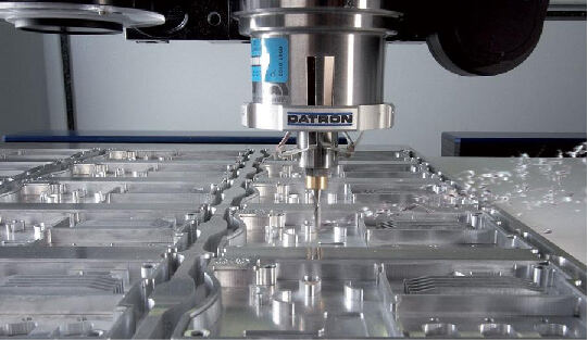
Prototype CNC machining is the process of using computer-controlled machine tools to create functional test versions of parts before committing to full-scale production. Unlike 3D printing or manual fabrication methods, this approach removes material from solid blocks of production-grade materials, delivering prototypes that closely replicate the strength, fit, and performance characteristics of final manufactured components.
From Digital Design to Physical Reality
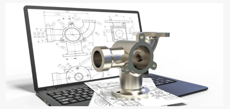
CNC prototyping transforms CAD models into tangible parts through automated precision cutting. The process begins with your digital design and ends with a component you can hold, test, and validate against real-world requirements. What makes this approach particularly powerful is material authenticity. When you machine a prototype from the same aluminum alloy or engineering plastic intended for production, you're not approximating performance—you're testing actual behavior.
Traditional prototyping methods often rely on substitute materials or simplified fabrication techniques. Manual machining introduces human variability, while some rapid prototyping technologies use materials that don't match production specifications. CNC prototype machining eliminates these compromises by offering:
- High dimensional accuracy with tolerances as tight as ±0.001 inches
- Smooth surface finishes suitable for functional testing
- Repeatable results across multiple prototype iterations
- Fast turnaround times, sometimes within a single day
Why Engineers Choose CNC for First-Article Parts
When mechanical performance matters, engineers consistently turn to CNC for first-article parts. The fundamental value proposition is straightforward: you're creating components from actual production materials rather than approximations. This means strength testing, thermal analysis, and assembly verification all yield meaningful data.
Consider how prototype machining fits within the broader product development lifecycle. During initial concept validation, CNC prototypes help teams confirm that designs translate correctly from screen to physical form. Through design iteration phases, machined parts reveal issues that simulations might miss—interference fits, tolerance stack-ups, or unexpected stress concentrations. Finally, during pre-production verification, these prototypes serve as benchmarks for machining for manufacturing processes, ensuring smooth transitions to volume production.
CNC prototyping bridges the gap between design and manufacturing by validating design accuracy, testing real-world performance, identifying improvements early, and reducing costly production errors. For teams developing automotive components, medical devices, or aerospace hardware, this capability isn't optional—it's essential for confident product launches.
How CNC Prototype Parts Move from CAD File to Finished Component
So you've validated your design concept and selected CNC machining as your prototyping method. What happens next? Understanding the complete journey from digital file to finished part helps you prepare better documentation, avoid delays, and communicate effectively with your manufacturing partner. Let's walk through each stage of the CNC machining prototype process.
The Five Stages of CNC Prototype Production
Every CNC machining prototyping project follows a logical sequence. While timelines vary based on complexity, the fundamental steps remain consistent whether you're producing a simple bracket or a precision aerospace component.
-
File Preparation and Submission
The process begins with your 3D CAD model. Most machine shops accept standard neutral formats that translate geometry accurately across different software platforms. The most reliable options include:- STEP (.stp, .step) - The industry standard for solid model exchange
- IGES (.igs, .iges) - Widely compatible, though sometimes loses feature data
- Parasolid (.x_t) - Excellent for complex geometry
- Native formats (SolidWorks, Inventor, Fusion 360) - Accepted by many shops but may require conversion
-
Design for Machining Review
Experienced technologists analyze your file for manufacturability before quoting. They check for features that may be impossible or unnecessarily expensive to machine—like deep pockets with small corner radii, extremely thin walls, or internal geometries requiring specialized tooling. This review often reveals opportunities to reduce cost by 20-30% through minor design modifications. -
Material Selection and Stock Preparation
Based on your specifications, the shop sources appropriate raw material. For CNC milling operations, this typically means aluminum billet, steel bar stock, or engineering plastic sheets. Material certificates may be provided for applications requiring traceability. -
CAM Programming and Toolpath Generation
Using computer-aided manufacturing software, programmers translate your 3D model into G-code—the machine-readable instructions controlling every cut. This stage involves selecting appropriate cutting tools, determining optimal speeds and feeds, and planning the sequence of operations to achieve required tolerances. -
CNC Machining Milling and Finishing
The physical machining begins. Depending on part complexity, this may involve 3-axis, 4-axis, or 5-axis equipment. After primary machining, parts often require secondary operations like deburring, surface finishing, or heat treatment before final inspection.
Critical Checkpoints That Ensure Part Accuracy
Quality control isn't a single step—it's woven throughout the entire sample machining process. Here's where verification happens:
- Pre-production verification: Confirming material specifications match requirements
- First-article inspection: Measuring initial parts against CAD geometry before continuing the batch
- In-process checks: Monitoring critical dimensions during machining
- Final inspection: Comprehensive dimensional verification using CMM, optical comparators, or calibrated gauges
Common file issues that delay projects—and how to avoid them:
| Issue | Impact | Prevention |
|---|---|---|
| Inconsistent units (mm vs. inches) | Programming errors, incorrect dimensions | Verify unit settings before export; note units in documentation |
| Missing tolerance specifications | Delays for clarification; parts may not meet functional needs | Include 2D drawing with GD&T callouts for critical features |
| Undefined material | Quote delays; potential wrong material selection | Specify exact alloy grade (e.g., 6061-T6, not just "aluminum") |
| Non-machinable geometry | Redesign required; timeline extensions | Consult design for machining guidelines; request DFM feedback early |
| Corrupted or incompatible files | Complete submission rejection | Export to STEP format; verify file opens correctly before sending |
A well-prepared data package allows programming to begin almost immediately upon receipt. Include a brief project description noting quantity needed, desired lead time, any special requirements, and your preferred communication method for technical questions. This preparation directly translates to faster turnaround and fewer revision cycles.
With your files properly prepared and the production process understood, the next critical decision involves choosing the right manufacturing method for your specific prototype requirements.
CNC Prototyping vs 3D Printing vs Injection Molding Decision Guide
You've prepared your CAD files, understood the production process, and now face a pivotal question: is CNC machining actually the right choice for your prototype? The answer depends on what you're trying to accomplish. Each manufacturing method—CNC machining, 3D printing, and injection molding—excels in specific scenarios. Making the wrong choice can mean wasted budget, extended timelines, or prototypes that fail to validate what matters most.
Rather than defaulting to one method, successful engineering teams evaluate each project against clear decision criteria. Let's break down exactly when each approach delivers the best results.
When CNC Beats Additive Manufacturing
CNC prototyping dominates when your testing demands production-equivalent material properties. Consider a functional metal prototype for an automotive suspension component. You need to verify fatigue resistance under cyclic loading. A 3D printer that prints metal can create a similar geometry, but metal 3D printing often produces parts with anisotropic properties—meaning strength varies depending on the direction of applied force relative to build layers. CNC-machined parts from wrought aluminum or steel exhibit consistent, isotropic mechanical behavior identical to production components.
Here's when CNC machining is your strongest choice:
- Tight tolerance requirements: CNC delivers dimensional accuracy within ±0.025 mm—significantly tighter than most additive processes
- Surface finish matters: Machined parts come off the table with smooth, consistent finishes requiring minimal post-processing
- Real material testing: When you need actual 6061-T6 aluminum or 303 stainless steel properties, not approximations
- Medium quantities (20-5,000 units): CNC offers favorable economies of scale at volumes where 3D printing becomes expensive
SLA 3D printing and SLS 3D printing technologies have improved dramatically, but they still serve different purposes. SLA produces excellent surface detail for visual models, while SLS creates functional nylon parts suitable for snap-fit testing. Neither matches CNC for metal prototypes requiring precise tolerances and verified mechanical performance.
Material Properties That Drive Method Selection
Your material requirements often make the decision for you. Plastic molding through injection moulding requires significant upfront tooling investment, making it impractical for true prototyping unless you're validating production intent. Meanwhile, a metal 3D printer offers design freedom but limits your material choices and may require extensive post-processing.
The comparison matrix below provides actionable criteria for your decision:
| Criteria | CNC Machining | 3D Printing | Injection Molding |
|---|---|---|---|
| Dimensional Accuracy | ±0.025 mm standard | ±0.1 mm typical | ±0.05 mm (mold dependent) |
| Metal Options | Extensive: aluminum, steel, titanium, brass, copper | Limited: stainless, titanium, Inconel, cobalt chrome | Not applicable |
| Plastic Options | Engineering grades: ABS, Delrin, nylon, PEEK, polycarbonate | PA (nylon), ABS-like, PC-like, TPU | Broadest selection of thermoplastics |
| Surface Finish | Excellent as-machined; minimal post-processing | Layer lines visible; often requires finishing | Excellent; determined by mold quality |
| Mechanical Properties | Isotropic; matches production materials | Anisotropic; varies by build direction | Isotropic; production-equivalent |
| Cost per Part (1-20 units) | Moderate to high | Low to moderate | Very high (tooling amortization) |
| Cost per Part (100+ units) | Favorable | High | Low (after tooling) |
| Lead Time | Days to 2 weeks | Hours to days | Weeks to months (tooling) |
| Minimum Practical Quantity | 1 unit | 1 unit | 500-1,000+ units |
| Geometric Complexity | Moderate; limited by tool access | High; internal channels, organic shapes | Moderate; draft angles required |
Scenario-Based Selection Guide
Real-world projects rarely fit neat categories. Here's how experienced teams match methods to specific prototype objectives:
Choose CNC machining when:
- Testing functional metal components that will experience mechanical stress
- Validating fit and assembly with production-intent tolerances
- Creating 20-5,000 parts where per-unit economics favor machining
- Surface finish or cosmetic requirements are critical
Choose 3D printing when:
- Rapid design iteration matters more than material fidelity
- Complex internal geometries can't be machined
- You need concept models in hours, not days
- Quantities are very low (under 10-20 units) and tolerances are loose
Choose injection moulding when:
- Validating production-intent plastic materials at scale
- Quantities exceed 5,000 units and tooling investment is justified
- Testing mold flow behavior and gate locations matters
- Final cosmetic appearance must match mass-production output
Hybrid Approaches for Complex Projects
The most efficient product development workflows don't commit to a single method. Instead, they leverage each technology's strengths across different project phases:
- Concept validation: Use 3D printing metal or plastic parts for rapid geometry checks and stakeholder reviews
- Functional testing: Transition to CNC machined prototypes for mechanical validation with real materials
- Pre-production verification: If volumes justify tooling, produce injection-molded samples to confirm manufacturability
According to Trustbridge's manufacturing analysis, applying this tiered approach with design-for-manufacturability principles early can reduce time-to-market by 25-40% and lower production costs by up to 50%.
Some teams even combine methods within a single part. Post-processing machining on 3D-printed components delivers the geometric complexity of additive manufacturing with the precision of CNC on critical features—particularly valuable for complex metal parts requiring tight-tolerance interfaces.
Understanding which method fits your prototype goals is only half the equation. The material you select within that method dramatically affects both performance validation and cost. Let's examine how to match materials to functional requirements.
Material Selection Strategies for Functional CNC Prototypes
You've determined that CNC machining is the right method for your prototype. Now comes a decision that will define whether your part actually performs as intended: which material should you choose? This isn't just about picking something that machines well—it's about matching material properties to your functional requirements while keeping costs reasonable.
The right material selection starts with understanding your priorities. According to Protolabs' materials guidance, the first step is to list your must-haves and work down to nice-to-haves. This approach naturally narrows your options to a manageable set. Consider factors like operating temperature, chemical exposure, mechanical loading, weight constraints, and whether you're testing for production intent or simply validating geometry.
Aluminum Alloys for Lightweight Functional Prototypes
When engineers need functional metal prototypes with excellent strength-to-weight ratios, aluminum sheet metal stock is typically the starting point. Two grades dominate CNC prototyping applications:
- 6061-T6 Aluminum: The workhorse alloy for general-purpose prototyping. It offers excellent machinability, good corrosion resistance, and weldability. Ideal for structural components, brackets, housings, and fixtures. Achievable tolerances reach ±0.001 inches (0.025 mm) on critical features. Cost-effective and widely available in various stock sizes.
- 7075-T6 Aluminum: When strength matters more than corrosion resistance, this aerospace-grade alloy delivers. Tensile strength approaches that of many steels at one-third the weight. Choose 7075 for load-bearing prototypes, aerospace components, and high-stress applications. Slightly more expensive than 6061 but machines exceptionally well.
For aluminum parts requiring enhanced durability or cosmetic finish, consider secondary processes. Anodizing adds a protective oxide layer ideal for wear resistance, while chromate plating provides better cosmetic results. Protolabs now offers aluminum parts up to 22 x 14 x 3.75 inches—large enough for vibration testing fixtures and substantial structural components.
Stainless Steels and Specialty Metals
When corrosion resistance, temperature performance, or specific industry certifications matter, consider these options:
- 303 Stainless Steel: The most machinable stainless grade. Excellent for prototypes requiring corrosion resistance without extreme strength demands. Common in food processing, medical, and marine applications.
- 316 Stainless Steel: Superior corrosion resistance, especially in chloride environments. Harder to machine than 303, increasing costs 15-25%. Choose for chemical processing or marine prototypes.
- Brass sheet metal: Outstanding machinability with natural antimicrobial properties. Ideal for electrical connectors, decorative components, and plumbing fixtures. Machines quickly, reducing cycle time and cost.
- Titanium (Grade 5/Ti-6Al-4V): Exceptional strength-to-weight ratio and biocompatibility. Essential for aerospace and medical implant prototypes. Expect 3-5x the cost of aluminum due to material price and slower machining speeds.
Metal tolerances generally follow this hierarchy: aluminum achieves the tightest tolerances most economically, followed by brass and stainless steels, with titanium requiring more careful process control. Standard tolerances of ±0.005 inches apply across most metals, with tighter specifications available through GD&T callouts.
Engineering Plastics That Simulate Production Performance
Plastic prototypes offer distinct advantages: lighter weight, lower material costs, faster machining times, and reduced tool wear. However, as Hubs notes, plastics present unique challenges including heat sensitivity, potential dimensional instability, and lower tensile strength compared to metals.
When comparing acetal vs delrin, you'll find they're actually the same material—Delrin is DuPont's brand name for acetal (POM). This engineering plastic excels for:
- Delrin/Acetal (POM): Low friction, excellent dimensional stability, and moisture resistance. Perfect for gears, bearings, bushings, and sliding components. Machines beautifully with tight tolerances achievable (±0.002 inches typical).
- ABS plastic sheet: Good impact resistance and surface finish at moderate cost. Ideal for housings, enclosures, and consumer product prototypes. ABS CNC machining produces smooth surfaces suitable for painting or plating. Note that ABS can soften under heat during aggressive cutting.
- Nylon (PA): Excellent for machining when you need wear resistance and toughness. Nylon for machining applications includes gears, wear pads, and structural components. Be aware that nylon absorbs moisture, which can cause dimensional changes of 1-3%—factor this into tolerance specifications.
- Polycarbonate sheet: Outstanding impact resistance and optical clarity. Choose for transparent prototypes, safety shields, and electronic enclosures. Achieves good tolerances but requires careful chip evacuation to prevent heat buildup.
- PEEK: The premium choice for high-temperature and high-strength plastic applications. Biocompatible grades suit medical prototypes; glass-filled versions approach metal stiffness. Expect material costs 10-20x higher than commodity plastics.
Plastic tolerance specifications differ from metals. Standard surface roughness for flat machined surfaces is 63 µin, while curved surfaces achieve 125 µin or better. Thin-walled plastic parts may experience warpage after machining due to internal stress release—GD&T flatness callouts can control this by defining parallel planes within which surfaces must lie.
Matching Materials to Functional Requirements
Rather than selecting materials based solely on familiarity, work backward from your prototype's purpose:
| Functional Requirement | Recommended Metals | Recommended Plastics |
|---|---|---|
| High strength, lightweight | 7075 Aluminum, Titanium | PEEK, Glass-filled Nylon |
| Corrosion resistance | 316 Stainless, Titanium | PTFE, PVC, Delrin |
| Low friction/wear surfaces | Brass | Delrin, PTFE, Nylon |
| High temperature operation | Stainless Steel, Titanium | PEEK, Ultem |
| Optical clarity | — | Polycarbonate, PMMA (Acrylic) |
| Electrical insulation | — | ABS, Polycarbonate, Nylon |
| Cost-optimized general use | 6061 Aluminum, Brass | ABS, Delrin |
If your machined prototypes will eventually transition to injection molding, select CNC materials matching your production intent. ABS, acetal, nylon, and polycarbonate are all available in both machinable stock and injection-moldable resin grades—giving you prototypes that perform identically to production parts.
With materials matched to your functional requirements, the next consideration is how industry-specific standards might further constrain your choices and add documentation requirements to your prototype project.
Industry-Specific Requirements for Precision Prototype Components
You've selected the right manufacturing method and chosen appropriate materials. But here's where prototype projects often stumble: overlooking the specific requirements your industry demands. A machined part that performs flawlessly in functional testing may still fail to meet certification standards, delaying your path to production. Whether you're developing automotive chassis components or medical implants, understanding these requirements upfront prevents costly surprises.
Each regulated industry imposes distinct expectations for CNC machining parts—from tolerance specifications and material traceability to testing protocols and documentation depth. Let's examine what these requirements actually mean for your prototype project.
Automotive Prototype Requirements and Certification Standards
Automotive prototypes face intense scrutiny because failures can cascade into safety recalls affecting millions of vehicles. When developing metal machining parts for automotive applications, you'll encounter requirements beyond basic dimensional accuracy.
The IATF 16949 quality management standard—built on ISO 9001 foundations—represents the minimum expectation for automotive suppliers. According to 3ERP's certification guide, this standard emphasizes risk management, configuration control, and complete product traceability. For prototype machining, this translates to specific documentation requirements:
- Material certifications: Mill test reports documenting chemical composition, mechanical properties, and heat treatment history for every material lot
- Dimensional inspection records: First-article inspection reports with measurement data for all critical features, often requiring Capability studies (Cpk values)
- Process documentation: Recorded machining parameters, tool specifications, and operator qualifications
- Change control: Documented approval process for any design or process modifications during prototype development
Statistical Process Control (SPC) requirements extend even to prototype phases when parts are destined for validation testing. You'll need to demonstrate process stability through control charts and capability indices, particularly for safety-critical dimensions on machined metal parts like brake components, steering linkages, or structural assemblies.
Tolerance expectations in automotive prototyping typically demand:
- ±0.05 mm for general features
- ±0.025 mm for mating surfaces and bearing fits
- ±0.01 mm for critical safety features with documented Cpk ≥1.33
Quality testing for CNC machined parts in automotive applications often includes fatigue testing, corrosion resistance validation (salt spray testing), and functional verification under simulated operating conditions.
Medical Device Prototyping Compliance Considerations
Medical device prototyping operates under a fundamentally different paradigm: patient safety drives every decision. The FDA's regulatory framework requires documented evidence that your design and manufacturing processes will consistently produce safe, effective devices.
According to EST's FDA compliance guide, manufacturers must address three critical areas during cnc machined prototypes development:
Material Compliance:
- Biocompatibility verification: Materials contacting body tissues require USP Class VI or ISO 10993 testing documentation
- FDA-approved materials: Medical-grade stainless steels (316L), titanium alloys (Ti-6Al-4V ELI), and PEEK polymers with documented biocompatibility
- Material traceability: Lot-level tracking from raw material through finished prototype, enabling complete recall capability if needed
Design Control Documentation:
FDA regulations mandate maintaining a Design History File (DHF) throughout development. Even at the prototype stage, you should document:
- Design inputs and outputs for each iteration
- Risk analysis using Failure Mode and Effects Analysis (FMEA)
- Verification and validation test protocols and results
- Design reviews and approval signatures
Quality Management System Alignment:
ISO 13485 certification—the medical device equivalent of ISO 9001—provides the framework for compliant prototype development. Key requirements include stringent documentation of design, manufacturing, and servicing processes, with emphasis on risk management and regulatory compliance.
Surface finish specifications for medical machined parts often exceed other industries—implants may require Ra values below 0.4 µm to minimize bacterial adhesion and tissue irritation.
Aerospace Component Validation Requirements
Aerospace prototyping combines the documentation rigor of medical with the performance demands of automotive—then adds extreme environmental requirements. AS9100 certification, built on ISO 9001 with aerospace-specific additions, serves as the baseline expectation.
- Material specifications: Aerospace alloys require conformance to AMS (Aerospace Material Specifications) or equivalent standards, with full metallurgical documentation
- Special process controls: Heat treatment, surface treatments, and non-destructive testing (NDT) require certified operators and documented procedures
- Configuration management: Every design revision, from initial prototype through production release, requires formal tracking and approval
- First-article inspection: AS9102 compliant documentation with balloon drawings and complete dimensional verification
Tolerance expectations for cnc machined prototypes in aerospace applications often reach ±0.0005 inches (0.013 mm) for critical interfaces, with surface finishes specified in microinches and verified through profilometry.
Industrial Equipment and General Manufacturing
Industrial equipment prototypes face less regulatory burden but still require attention to application-specific standards:
- Hydraulic and pneumatic components: Pressure vessel codes (ASME), leak testing protocols, and material compatibility verification
- Electrical enclosures: UL or CE marking requirements, IP rating verification, and RoHS/REACH material compliance documentation
- Food processing equipment: FDA 21 CFR compliance, 3-A Sanitary Standards, and surface finish requirements (typically Ra 0.8 µm or better)
- Heavy machinery: Load testing, safety factor verification, and weld qualification for fabricated assemblies
Documentation Checklist Across Industries
Regardless of your specific industry, professional prototype suppliers should provide—and you should request—appropriate documentation:
| Document Type | Automotive | Medical | Aerospace | Industrial |
|---|---|---|---|---|
| Material Certifications | Required | Required | Required | Recommended |
| Dimensional Inspection Report | Required | Required | Required | Recommended |
| Process Traceability | Required | Required | Required | Optional |
| First-Article Inspection | Required | Required | AS9102 Required | Optional |
| SPC/Capability Data | Often Required | Optional | Optional | Rare |
| Biocompatibility Testing | Not Applicable | Required | Not Applicable | Food Contact Only |
| Non-Destructive Testing | Safety Parts | Implants | Often Required | Pressure Components |
Planning for these requirements from the start of your prototype project prevents delays when transitioning to production. A machine shop experienced in your industry will understand these expectations and build appropriate documentation into their standard workflow.
Understanding industry requirements helps you spec your project correctly, but there's another factor that catches many teams off guard: cost. Let's examine what actually drives CNC prototype pricing and how design decisions affect your budget.
Understanding Cost Drivers and Budgeting for CNC Prototypes
Ever received a CNC machining quote that seemed surprisingly high—or puzzlingly low? You're not alone. Pricing for cnc parts often feels opaque, leaving engineering teams uncertain whether they're getting fair value or leaving money on the table. The truth is, CNC prototype costs follow predictable patterns once you understand what drives them.
According to RapidDirect's cost analysis, up to 80% of manufacturing cost gets locked in during the design phase. That means the decisions you make before submitting your CAD file have more impact on pricing than any negotiation afterward. Let's break down exactly what affects your quote and how to optimize each factor.
What Actually Drives CNC Prototype Costs
Every cnc machining part quote reflects a simple formula: Total Cost = Material Cost + (Machining Time × Machine Rate) + Setup Cost + Finishing Cost. Understanding each component helps you identify where savings are possible.
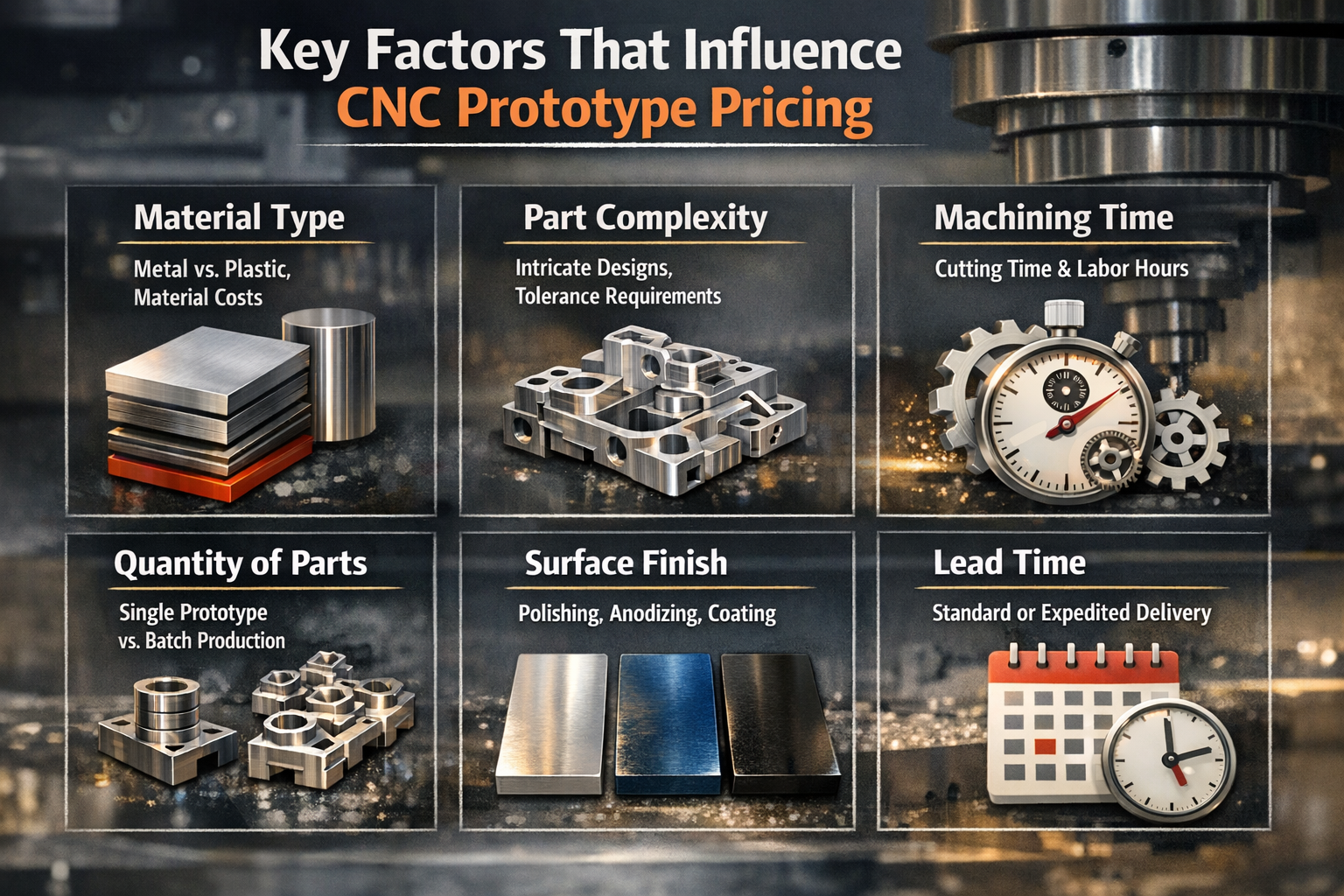
- Material type and volume: Raw stock prices vary dramatically—aluminum costs a fraction of titanium, while engineering plastics like PEEK can exceed many metals. Parts requiring oversized stock due to unusual dimensions generate more waste, increasing material expense. Designing around common stock sizes minimizes scrap.
- Geometric complexity: This is typically the largest cost driver. Deep pockets with small corner radii, thin walls, and intricate features require slower cutting speeds, multiple tool changes, and sometimes specialized tooling. Every additional setup or operation adds machine time.
- Tolerance requirements: Standard tolerances (±0.005 inches) cost less because machines can run at optimal speeds. Tighter specifications demand slower feeds, additional inspection time, and higher scrap risk. According to Dadesin's analysis, relaxing non-critical tolerances can reduce costs by 20-30%.
- Surface finish specifications: As-machined finishes add minimal cost. But mirror polishing, anodizing, powder coating, or electroplating each require additional labor, equipment time, and materials—especially on complex geometries requiring hand finishing.
- Order quantity: Setup costs remain fixed regardless of batch size. A $300 programming and fixturing charge adds $300 to a single-piece order but only $3 per part when spread across 100 units. This is why single prototypes carry higher per-unit pricing.
- Lead time urgency: Standard production schedules (7-10 days) offer the best pricing. Rush orders requiring 1-3 day turnaround demand overtime labor, priority machine scheduling, and expedited material sourcing—often adding 25-50% to the base quote.
Smart Strategies to Reduce Per-Part Pricing
Knowing what drives costs is only half the equation. Here's how to apply that knowledge to your cnc part designs:
- Design for standard tooling: Use common drill diameters, standard thread sizes (M3, M5, ¼-20), and internal corner radii that match standard end mill sizes. Every non-standard tool adds changeover time and potential custom tool procurement.
- Reduce setup complexity: Parts machined from a single setup cost less than those requiring repositioning. Design features accessible from one direction when possible. If multiple setups are unavoidable, minimize the number of fixture changes needed.
- Batch similar parts: Ordering multiple prototype variations simultaneously allows shops to optimize programming and tooling across the batch. Even different parts using the same material and similar features can share setup costs.
- Choose appropriate tolerances: Apply tight tolerances only to features requiring them—mating surfaces, bearing fits, or critical alignments. General dimensions can often accept ±0.010 inches without functional impact.
- Select machinable materials: When performance requirements allow, 6061 aluminum and ABS plastic offer the best cost-to-machinability ratio. Harder materials like stainless steel or titanium require slower cutting speeds and generate higher tool wear costs.
When to Prioritize Speed Over Cost
Not every prototype decision should optimize for minimum price. Consider prioritizing speed when:
- Design iterations are ongoing and you need rapid validation to make decisions
- Customer deadlines or trade show dates create hard constraints
- Delayed prototypes block downstream testing that multiple team members depend on
- The cost difference represents a small fraction of total project budget
When to Prioritize Cost Over Speed
Conversely, optimize for cost efficiency when:
- Design is stable and you're producing validation quantities (10-50 units)
- Budget constraints are fixed and timeline flexibility exists
- You're ordering multiple prototype variants and can batch them together
- Pre-production verification allows standard lead times
Custom manufacturing services providers increasingly offer instant quoting tools with automated design-for-manufacturability (DFM) feedback. These platforms flag cost-driving features before you commit—highlighting thin walls, deep pockets, or tight tolerances that inflate pricing. Using these tools during design iteration helps you understand how much to get a metal part made before finalizing specifications.
Understanding cost drivers empowers better decisions, but even well-budgeted projects can derail through preventable mistakes. Let's examine the common pitfalls that delay CNC prototype timelines and how to avoid them.
Common CNC Prototype Mistakes and How to Prevent Them
You've budgeted carefully, selected appropriate materials, and submitted what you thought was a production-ready design. Then the email arrives: "We need to discuss some issues with your file before proceeding." Sound familiar? Even experienced engineers encounter preventable delays in their prototype machining projects. According to James Manufacturing's analysis, prototyping mistakes create a ripple effect—increasing material waste, extending timelines, and eroding stakeholder confidence.
The good news? Most CNC prototype failures follow predictable patterns. Understanding these patterns transforms frustrating surprises into preventable obstacles. Let's examine the mistakes that derail projects and the specific actions that keep your cnc milled parts on schedule.
Design Mistakes That Delay Your Prototype Timeline
When designs arrive at the machine shop, technologists review them for manufacturability before programming begins. Features that seem reasonable on screen may be impossible—or prohibitively expensive—to machine. Here are the issues that trigger revision requests most frequently:
Insufficient Wall Thickness
Thin walls flex under cutting forces, causing vibration, poor surface finish, and dimensional inaccuracy. Worse, excessively thin features can break during machining or subsequent handling.
- Prevention: Maintain minimum wall thickness of 0.8 mm for metals and 1.5 mm for plastics. If thinner walls are functionally necessary, discuss fixturing strategies with your shop before finalizing the design.
Impossible Internal Features
CNC milling components requires tool access. Internal corners can never be perfectly sharp because the rotating end mill has a defined radius. Similarly, deep narrow pockets may be unreachable with any available cutting tool.
- Prevention: Design internal corner radii at least 1/3 of pocket depth. For deep cavities, specify the largest acceptable corner radius—this allows use of more rigid tools that produce better milled parts with superior surface quality.
Tolerance Stack-Up Problems
When multiple toleranced dimensions combine in an assembly, their variations accumulate. As noted by HLH Rapid's tolerance guide, stack-up analysis using worst-case calculations helps prevent fit or function issues when parts mate together.
- Prevention: Perform tolerance stack-up analysis before finalizing critical interface dimensions. Use geometric dimensioning and tolerancing (GD&T) to control feature relationships rather than relying solely on linear tolerances.
Material Selection Mismatches
Choosing materials without considering machinability, thermal properties, or post-processing requirements leads to disappointing results. A prototype machined from free-cutting steel won't predict performance of a production part in hardened tool steel.
- Prevention: Match prototype materials to production intent whenever functional testing matters. Document your material selection rationale so subsequent iterations maintain consistency.
Incomplete Documentation
A 3D model alone rarely communicates complete manufacturing intent. Missing tolerance callouts, unspecified surface finishes, or absent thread specifications force shops to guess—or pause for clarification.
- Prevention: Always include a 2D drawing with your 3D CAD file. Call out critical dimensions, specify surface finish requirements (Ra values), and identify any features requiring special attention. According to industry best practices, documenting every step creates a knowledge repository that prevents repeated mistakes.
Unrealistic Timeline Expectations
Rushing the prototyping process frequently results in overlooked errors. Compressed schedules eliminate the review time that catches problems before they become expensive.
- Prevention: Build realistic buffers into project schedules. If fast turnaround is essential, simplify the design to reduce programming and machining complexity rather than compressing quality checks.
How to Avoid Costly Revision Cycles
Revision cycles waste more than money—they consume calendar time that compounds through your entire development schedule. Understanding the parts of a cnc mill and how they interact with your geometry helps you design parts that machine correctly the first time.
Pros: Benefits of Proper Preparation
- First-article parts meet specifications without rework, accelerating validation testing
- Machine shops can optimize toolpaths for speed rather than working around design limitations
- Clear documentation eliminates clarification delays that add days to quoted lead times
- Consistent material selection enables meaningful comparison across prototype iterations
- Realistic timelines allow thorough inspection, catching issues before parts ship
Cons: Consequences of Common Mistakes
- Design revisions restart programming and material procurement, often adding 3-5 days per cycle
- Milling marks and surface defects on thin-walled features may require complete re-machining
- Tolerance stack-up failures discovered during assembly waste all upstream machining time
- Wrong material choices invalidate functional test results, requiring repeat prototype runs
- Incomplete specs result in parts that technically match the drawing but don't meet actual needs
Effective Communication Strategies with Machine Shops
Many prototype delays stem not from technical problems but from communication gaps. According to Premium Parts' defect prevention guide, lack of communication between design and production teams causes inevitable misalignments.
Here's how to communicate effectively:
- Provide context beyond the geometry: Explain what the part does and which features are functionally critical. This helps machinists prioritize accuracy where it matters most.
- Request DFM feedback early: Ask for design-for-manufacturability review before finalizing specs. Experienced cnc milling components technologists often suggest minor changes that dramatically reduce cost or improve quality.
- Establish preferred communication channels: Email works for documentation, but phone or video calls resolve ambiguities faster. Identify your technical contact and their availability upfront.
- Clarify inspection requirements: Specify which dimensions require formal measurement reports versus standard process controls. This prevents both over-inspection (adding cost) and under-inspection (missing issues).
- Discuss acceptable alternatives: If a feature proves difficult to machine as designed, are you open to modifications? Communicating flexibility enables shops to propose solutions rather than simply flagging problems.
The best prototype partnerships treat DFM review as collaborative problem-solving rather than design criticism. Shops want your project to succeed—their reputation depends on delivering quality cnc milled parts that meet your needs.
Preventing mistakes requires both technical knowledge and partnership with capable manufacturing partners. The next consideration is evaluating which CNC prototyping supplier can deliver the quality, communication, and scalability your project demands.

Choosing a CNC Prototype Partner That Scales with Your Project
You've refined your design, selected appropriate materials, and prepared documentation to prevent costly delays. Now comes a decision that can make or break your prototype timeline: which cnc prototyping service should manufacture your parts? Searching for "cnc machine shops near me" returns dozens of options, but capability varies dramatically. The shop that delivered adequate results on a simple bracket may struggle with complex aerospace components requiring tight tolerances.
According to EcoRepRap's scalability analysis, choosing the right CNC partner is key to achieving scalable production—from initial cnc prototypes through volume manufacturing. The evaluation criteria below help you identify partners capable of growing with your project rather than becoming bottlenecks when production demands increase.
Capability Indicators That Signal Quality Manufacturing
Not every prototype machine shop operates at the same level. Before requesting quotes, assess fundamental capabilities that predict reliable outcomes:
Equipment Capabilities
The machines a shop operates directly limit what they can produce. Understanding these distinctions helps you match projects to appropriate providers:
- 3-axis CNC mills: Handle most prismatic parts with features accessible from one direction. Adequate for brackets, housings, and simple components. Lower hourly rates but may require multiple setups for complex geometry.
- 4-axis machining: Adds rotational capability for cylindrical features and reduces setups on parts requiring machining from multiple angles.
- 5 axis CNC machine: Enables complex contoured surfaces, undercuts, and intricate geometries in single setups. Essential for aerospace components, impellers, and medical implants. Shops offering 5 axis cnc machining services command premium rates but deliver superior accuracy on challenging parts.
- CNC turning centers: Required for rotational parts like shafts, bushings, and cylindrical housings. Multi-axis turn-mill combinations handle complex turned parts with milled features.
Ask specifically about machine brands, age, and maintenance schedules. Modern equipment with current controls produces more consistent results than aging machinery—regardless of axis count.
Quality Certifications
Certifications indicate documented quality systems, not just good intentions. According to Unisontek's evaluation guide, compliance with recognized standards demonstrates well-documented procedures, traceability systems, and continuous improvement processes:
- ISO 9001: The baseline quality management standard. Demonstrates commitment to documented processes but doesn't address industry-specific requirements.
- IATF 16949: Essential for automotive suppliers. Adds requirements for risk management, statistical process control, and supply chain management beyond ISO 9001.
- AS9100: Required for aerospace manufacturing. Emphasizes configuration control, special process management, and comprehensive traceability.
- ISO 13485: Specific to medical device manufacturing. Addresses biocompatibility documentation, design controls, and regulatory compliance.
Request copies of current certificates and verify expiration dates. Ask about recent audit findings and how the shop addressed any non-conformances.
Inspection Equipment and Practices
Quality outcomes depend on measurement capability. Sophisticated shops invest in advanced inspection tools to verify tolerances and geometries:
- Coordinate Measuring Machines (CMMs): Essential for dimensional verification of complex geometry. Ask about measurement uncertainty and calibration schedules.
- Surface roughness testers: Required when surface finish specifications matter for function or appearance.
- Optical comparators: Useful for profile verification and 2D feature inspection.
- Non-destructive testing capabilities: Ultrasonic, dye penetrant, or magnetic particle inspection for detecting hidden flaws in critical components.
Questions to Ask Before Committing to a Prototype Supplier
Beyond equipment and certifications, operational practices determine whether a shop delivers consistently. According to Lakeview Precision's partner selection guide, these questions reveal capability depth:
Experience and Expertise
- Have you produced similar parts before? Request examples or case studies from comparable projects.
- What materials do you work with regularly? Shops develop expertise with specific alloys—aluminum specialists may struggle with titanium or exotic alloys.
- Can you provide references from customers in my industry? Direct feedback from similar applications reveals real-world performance.
Process Control and Documentation
- Do you perform First Article Inspection (FAI)? This verification ensures initial parts meet requirements before full production proceeds.
- How do you implement Statistical Process Control (SPC)? Tracking production data prevents deviations before they create scrap.
- What traceability do you maintain? Recording material certifications, batch numbers, and inspection results enables accountability and recall capability.
Communication and Responsiveness
- Who will be my technical contact? Direct access to engineers or project managers accelerates problem resolution.
- How do you handle design clarification requests? Proactive communication about potential issues prevents delays.
- What's your typical response time for quotes and technical questions? Responsiveness during quoting predicts communication quality during production.
Scalability from Prototype to Production
The most efficient development workflows use the same partner from initial prototypes through volume production. According to manufacturing scalability research, partnering with experienced CNC companies reduces risks and ensures predictable scaling outcomes:
- Can you handle quantities from 1 to 10,000+ parts? Understanding capacity limits prevents mid-project partner changes.
- How does pricing evolve as quantities increase? Volume discounts and setup amortization should reduce per-part costs at scale.
- What's your lead time for prototype versus production quantities? Shops optimized for online cnc machining services may offer rapid prototyping but struggle with production scheduling.
Red Flags That Signal Potential Problems
Equally important as identifying qualified partners is recognizing warning signs that predict trouble:
- Reluctance to discuss capabilities: Quality shops welcome detailed questions about equipment and processes.
- No formal quality system: Even for prototype work, documented procedures prevent errors and enable traceability.
- Unrealistic pricing or lead times: Quotes significantly below market rates often indicate corner-cutting that affects quality.
- Poor communication during quoting: If responses are slow or incomplete before you've placed an order, expect worse performance afterward.
- No references or portfolio: Established shops can demonstrate relevant experience through past work examples.
Example: What a Qualified Partner Looks Like
Consider Shaoyi Metal Technology as an illustration of the capabilities to seek in a prototype partner. Their IATF 16949 certification demonstrates automotive-grade quality management, while their Statistical Process Control practices ensure consistent dimensional accuracy across production runs. For teams developing chassis assemblies or custom metal bushings, this combination of certification and process control translates to reliable results.
What distinguishes capable partners is the ability to scale seamlessly—from rapid prototyping with lead times as fast as one working day through to mass production volumes. This scalability eliminates the risk of transitioning between suppliers mid-project, where institutional knowledge gets lost and quality inconsistencies can emerge. Explore their certified manufacturing capabilities for automotive machining applications.
Evaluation Checklist for CNC Prototype Partners
| Evaluation Criteria | Questions to Ask | What to Look For |
|---|---|---|
| Equipment Capability | What machine types and axis counts do you operate? | Match to your part complexity; 5-axis for contoured surfaces |
| Quality Certifications | Which certifications do you hold? When were they last audited? | Relevant industry standards (ISO, IATF, AS9100) |
| Inspection Equipment | What measurement capabilities do you have? | CMM, surface testers, NDT appropriate to your requirements |
| Material Expertise | What materials do you machine regularly? | Experience with your specific alloys or plastics |
| Process Documentation | How do you maintain traceability and process control? | FAI, SPC, material certification tracking |
| Communication | Who is my technical contact? How quickly do you respond? | Named contacts, responsive quotes, proactive clarification |
| Scalability | Can you handle prototype through production volumes? | Capacity for growth without supplier transitions |
| Lead Time | What are typical turnaround times for prototype quantities? | Alignment with your development schedule |
Selecting the right partner based on these criteria sets the foundation for successful prototype development. But individual prototypes are only milestones—the ultimate goal is integrating CNC prototyping into an efficient product development workflow that accelerates your path from concept to production launch.
Accelerating Product Development Through Strategic CNC Prototyping
You've selected the right manufacturing method, chosen materials that match production intent, prepared documentation to prevent delays, and identified a capable partner. Now comes the strategic question: how do you integrate rapid cnc prototyping into a workflow that consistently delivers products to market faster than your competition?
The difference between teams that struggle through development and those that launch confidently often isn't technical capability—it's process design. According to Protolabs' prototyping research, prototype models help design teams make more informed decisions by obtaining invaluable data from prototype performance. The more data gathered during this stage, the better the chances of preventing potential product or manufacturing issues downstream.
Building Iteration Speed into Your Development Process
Fast prototyping isn't about rushing—it's about eliminating waste between design decisions. Every day your team waits for machined prototypes is a day competitors might be testing their own designs. Here's how to structure your workflow for maximum velocity:
- Parallel path planning: While one prototype undergoes testing, prepare design modifications for the next iteration. When test results arrive, you're ready to submit updated files immediately rather than starting the design cycle from scratch.
- Tiered validation strategy: Use rapid cnc machining for functional validation of critical features while reserving comprehensive testing for later iterations. Not every prototype needs full dimensional inspection—match verification depth to development phase.
- Standardized file packages: Create templates for your CAD exports, tolerance specifications, and material callouts. Consistent documentation eliminates back-and-forth clarification that adds days to every order.
- Feedback loop acceleration: Establish clear criteria for prototype success before parts arrive. When machined prototypes meet your go/no-go checkpoints, decisions happen in hours rather than dragging through extended review cycles.
As noted in OpenBOM's best practices guide, the prototyping stage is essential for identifying design flaws, validating functionality, and gathering stakeholder feedback. With cnc rapid prototyping, developers can iterate quickly and cost-effectively, reducing risks and delays often associated with late-stage design changes.
The goal isn't just making prototypes faster—it's making better decisions sooner. Each iteration should answer specific questions that move your design toward production readiness.
From Validated Prototype to Production Launch
The transition from prototype to production is where many projects stumble. According to manufacturing transition research, moving from a one-off creation to a reproducible, cost-effective product often uncovers design flaws, material constraints, and production inefficiencies that weren't apparent during prototyping.
Strategic rapid prototyping cnc machining addresses these risks systematically:
Concept Validation Phase
Early prototypes confirm that digital designs translate correctly to physical form. Focus on:
- Basic fit and assembly verification
- Ergonomic evaluation for user-facing components
- Stakeholder review and feedback collection
- Initial cost-to-manufacture estimates
Design Iteration Phase
Functional testing reveals issues simulations miss. Your machined prototypes should validate:
- Mechanical performance under realistic loading conditions
- Thermal behavior in operating environments
- Tolerance stack-ups across mating components
- Design-for-manufacturability improvements
Pre-Production Verification Phase
Final prototypes serve as benchmarks for production processes. According to Protolabs' development guidance, even if your prototype design is functional and manufacturable, it doesn't mean anyone will want to use it—prototypes are the only true way to verify design viability through market trials and regulatory testing.
This phase confirms:
- Production tooling and fixturing requirements
- Quality control checkpoints and inspection criteria
- Supplier capability for volume manufacturing
- Regulatory compliance documentation completeness
Successful product launches aren't lucky—they're the result of systematic validation at each development stage. CNC prototyping provides the production-equivalent parts that make this validation meaningful.
The Decision-Making Framework in Practice
Throughout this guide, we've emphasized frameworks over formulas. That's intentional. Your specific project—its materials, tolerances, industry requirements, and timeline constraints—demands informed judgment rather than rigid rules.
Here's how the decision points connect:
| Development Stage | Key Decision | Framework Application |
|---|---|---|
| Method Selection | CNC vs. 3D printing vs. injection molding | Match method to functional requirements, tolerance needs, and quantity |
| Material Selection | Specific alloy or polymer grade | Balance performance requirements against cost and machinability |
| Tolerance Specification | Standard vs. tight tolerances | Apply precision only where function demands it |
| Partner Selection | Prototype shop vs. scalable manufacturer | Prioritize capability to grow from prototype through production |
| Timeline Planning | Speed vs. cost optimization | Match urgency to project phase and budget constraints |
Partnering for Seamless Scale-Up
The most efficient development workflows eliminate supplier transitions between prototyping and production. When your prototype partner can scale to volume manufacturing, the institutional knowledge built during development—material behaviors, critical tolerances, optimal machining strategies—transfers directly to production.
This is where certified partners demonstrate their value. Shaoyi Metal Technology exemplifies this scalable approach, offering precision CNC machining services that span from rapid prototyping with lead times as fast as one working day through to mass production volumes. Their IATF 16949 certification and Statistical Process Control practices ensure that the quality validated during prototyping carries through to every production part—whether you're developing complex chassis assemblies or high-tolerance custom metal bushings for automotive applications.
For engineering teams ready to accelerate their prototype projects with a partner capable of supporting the complete journey from concept to production, explore Shaoyi's automotive machining capabilities.
The best prototype isn't just a test part—it's the first step toward production-ready manufacturing. Choose partners who understand both phases.
Your Next Steps
Prototype CNC machining bridges the gap between digital designs and production-ready parts. The frameworks in this guide—for method selection, material choice, cost optimization, mistake prevention, and partner evaluation—equip you to make confident decisions at each development stage.
Whether you're validating an initial concept or preparing for production launch, the principles remain consistent: match your manufacturing method to functional requirements, design for manufacturability from the start, document thoroughly, and partner with capable manufacturers who can grow with your project.
Your next functional prototype is closer than you think. Apply these frameworks, prepare your files, and transform your CAD designs into production-validated components faster than ever before.
Frequently Asked Questions About Prototype CNC Machining
1. What is a CNC prototype?
A CNC prototype is a physical part created using computer numerical control machines that remove material from solid blocks of production-grade materials. Unlike 3D printing that builds layer by layer, CNC prototyping machines parts from actual aluminum, steel, titanium, or engineering plastics. This produces prototypes with isotropic mechanical properties identical to final production components, enabling accurate functional testing, fit verification, and performance validation before committing to full-scale manufacturing.
2. How much does a CNC prototype cost?
CNC prototype costs depend on material type, geometric complexity, tolerance requirements, surface finish specifications, quantity, and lead time urgency. Simple aluminum parts may cost significantly less than complex titanium components with tight tolerances. Up to 80% of manufacturing cost gets locked in during design—using standard tooling, appropriate tolerances only where needed, and batching similar parts can reduce costs by 20-30%. Rush orders typically add 25-50% to base pricing.
3. What does a prototype machinist do?
A prototype machinist programs and operates CNC equipment to create precision test parts from CAD files. Their responsibilities include reviewing designs for manufacturability, selecting appropriate cutting tools, determining optimal machining parameters, executing multi-axis operations, and inspecting finished components against specifications. Skilled prototype machinists troubleshoot issues during production and suggest design modifications that improve part quality while reducing manufacturing time and cost.
4. When should I choose CNC machining over 3D printing for prototypes?
Choose CNC machining when your prototype requires production-equivalent material properties, tight tolerances within ±0.025mm, smooth surface finishes, or medium quantities of 20-5,000 units. CNC excels for functional metal prototypes needing verified mechanical performance under stress, heat, or fatigue testing. 3D printing works better for rapid design iteration, complex internal geometries, concept models needed in hours, or very low quantities where tolerances are less critical.
5. What materials can be used for CNC prototype machining?
CNC prototyping supports extensive material options including aluminum alloys (6061-T6, 7075-T6), stainless steels (303, 316), brass, titanium, and engineering plastics like ABS, Delrin/acetal, nylon, polycarbonate, and PEEK. Material selection should match your functional requirements—7075 aluminum for high-strength aerospace parts, 316 stainless for corrosion resistance, Delrin for low-friction components, or PEEK for high-temperature applications. Certified partners like Shaoyi Metal Technology offer automotive-grade materials with full traceability.