 Small batches, high standards. Our rapid prototyping service makes validation faster and easier —

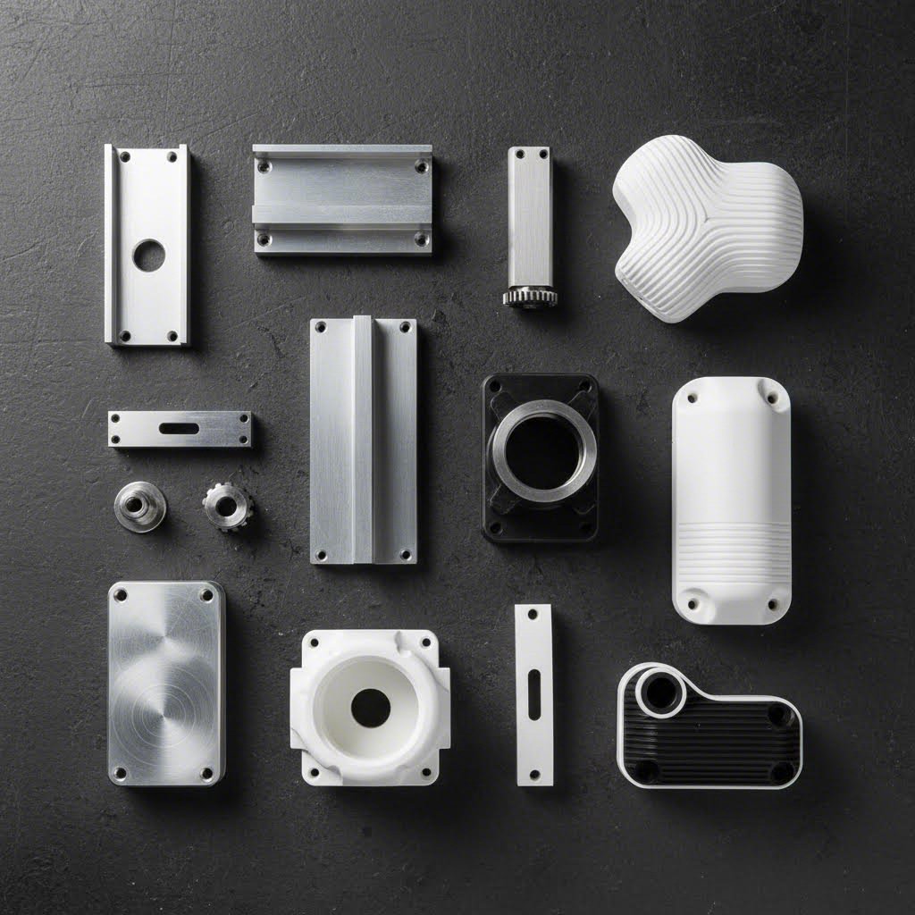
CNC Machining Prototyping: From CAD File To Production-Ready Parts
Understanding CNC Machining Prototyping Fundamentals
Ever wondered how product designers transform their digital concepts into physical parts they can actually hold, test, and refine? That's where CNC machining prototyping comes into play. It bridges the gap between your computer screen and real-world validation, giving you production-grade parts before committing to full-scale manufacturing.
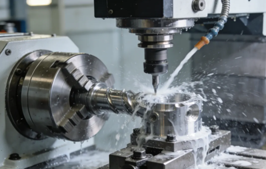
CNC machining prototyping is a subtractive manufacturing process that uses computer-controlled cutting tools to create functional prototype parts from solid blocks of metal or plastic, delivering production-quality components for design validation and testing.
Unlike 3D printing that builds parts layer by layer, this approach starts with a solid block of material and precisely removes everything that isn't your finished part. The result? A prototype with the same structural integrity and material properties as your final production components.
What Sets CNC Prototyping Apart from Standard Machining
You might be thinking: isn't all CNC machining basically the same? Not quite. The key difference lies in purpose and approach. Production machining focuses on efficiency and repeatability across thousands of identical parts. CNC prototyping, on the other hand, prioritizes flexibility, speed, and the ability to iterate quickly.
Here's what makes prototype machining distinct:
- Lower volumes: Typically one to a few dozen parts rather than thousands
- Design flexibility: Accommodates frequent design changes without expensive tooling modifications
- Faster turnaround: Quick-turn parts available within days, sometimes as fast as one day
- Validation focus: Parts intended for testing form, fit, and function before production commitment
According to PMP Metals, prototyping is a crucial step that reduces risk by allowing engineers to test their ideas before final production runs. This can save expensive reworks and prevent manufacturing defects or field failures—especially critical in industries like aerospace and automotive where even small design flaws can lead to significant problems.
Why Engineers Choose Subtractive Manufacturing for Prototypes
When you need a prototype that behaves exactly like your production part, CNC prototype machining delivers what additive methods often can't. The solid composition of machined parts provides structural integrity that layered 3D-printed components simply lack.
Consider this comparison from DATRON's testing: when comparing additive and subtractive prototypes under real-world stress, the machined part maintained its integrity while the 3D-printed version showed delamination and required repair mid-test.
Engineers choose machine prototyping for subtractive processes because they can:
- Test with actual production-grade materials like aluminum, stainless steel, and titanium
- Achieve tight tolerances as precise as ±0.001 in. (±0.025mm)
- Create superior surface finishes ranging from mirror-smooth to textured
- Validate durability under real operating conditions
This capability to prototype in end-use materials means your test results accurately reflect how production parts will perform. When you're machining for manufacturing validation, there's no substitute for parts made from the same material with the same properties as your final product.
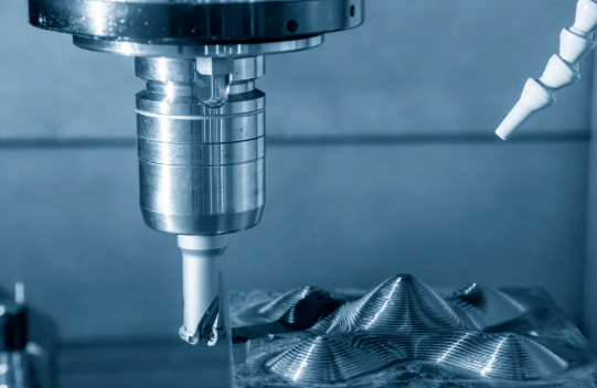
The Complete CNC Prototyping Workflow Explained
So you've designed something impressive in CAD software. Now what? Getting from that digital model to a physical CNC prototype involves more than just pressing a button. Understanding each step of the workflow helps you avoid costly delays and ensures your parts come out exactly as intended.
The CNC machining prototype process follows a systematic sequence that transforms your design into machine-readable instructions. Let's break down each phase so you know exactly what happens behind the scenes—and how to prepare your files for success.
- CAD Design Finalization: Complete your 3D model with all dimensions, tolerances, and feature specifications clearly defined
- File Export: Convert your design to a CNC-compatible format (STEP or IGES preferred)
- CAM Programming: Import the file into CAM software to generate toolpaths and cutting strategies
- G-Code Generation: Post-process the toolpaths into machine-specific instructions
- Machine Setup: Mount the workpiece, install cutting tools, and establish coordinate systems
- CNC Milling or Turning: Execute the programmed operations to create your prototype
- Quality Inspection: Verify dimensions against your original specifications
Each step builds upon the previous one. A mistake in file preparation can cascade through the entire process, causing rework and delays. That's why getting your CAD files right from the start matters so much.
Preparing Your CAD Files for Machining Success
Here's where many projects hit their first snag. Your CAD software might create beautiful renderings, but CNC machines speak a different language. According to JLCCNC, the same avoidable file preparation issues appear repeatedly—and they're entirely preventable.
Which file formats work best for CNC machining milling operations? Stick with these options:
- STEP (.stp, .step): The industry standard for transferring solid models between systems—preserves geometry accurately
- IGES (.igs, .iges): Widely compatible format that handles complex surfaces well
- Parasolid (.x_t, .x_b): Native format for many CAD systems with excellent data integrity
- Native CAD files: SolidWorks, Fusion 360, or Inventor files often accepted directly
Avoid mesh-based formats like STL or OBJ for CNC work. These files break smooth curves into tiny triangles—perfect for 3D printing but problematic for prototype CNC machining where precision matters. Your cnc prototype deserves better than approximated surfaces.
When exporting your design for machining, consider these critical factors:
- Tool access: Can cutting tools physically reach all features without collision?
- Internal corner radii: Match radii to available tool diameters (sharp internal corners aren't machinable)
- Wall thickness: Maintain minimum 0.5mm for metals, 1.0mm for plastics to prevent deflection
- Undercuts: Identify features requiring special tooling or multi-axis machining
From Digital Design to Physical Prototype
Once your CAD file is properly formatted, CAM software takes over. Programs like Mastercam, Fusion 360 CAM, or PowerMill analyze your geometry and calculate the optimal cutting paths. This is where design for machining principles become critical—your digital choices directly impact how efficiently the machine can produce your part.
The CAM programmer considers spindle speeds, feed rates, depth of cut, and tool selection for each operation. According to Yijin Hardware, modern CAM systems simulate toolpaths virtually, detecting potential collisions and optimizing cutting strategies before actual machining begins. This virtual testing reduces setup time and improves first-part quality.
Common file preparation mistakes that cause delays include:
- Missing dimensions or tolerances: Machinists can't guess your critical specifications
- Open surfaces or gaps: Non-watertight models confuse CAM software
- Overly complex geometry: Features that serve no functional purpose add machining time
- Incorrect scale: Models exported in wrong units (inches vs. millimeters) create chaos
- Embedded assembly components: Export only the part geometry, not fixtures or reference objects
After G-code generation, machine setup begins. Operators secure your raw material using vises, fixtures, or custom workholding devices. They install cutting tools and establish precise coordinate systems—aligning the machine's reference points to your part geometry within 0.0001" accuracy.
Finally, CNC milling operations execute the programmed sequences. Roughing passes remove bulk material quickly, semi-finishing operations approach final dimensions, and finishing passes achieve your specified surface quality. The entire process can happen in hours rather than weeks, making CNC prototyping the go-to choice when you need functional parts fast.
Understanding these workflow steps puts you in control. When you submit a properly prepared file with clear specifications, you're setting the stage for parts that match your vision—without the back-and-forth delays that frustrate both designers and machinists.
Tolerance Specifications and Precision Benchmarks
You've got your CAD file ready and understand the workflow. But here's a question that trips up many engineers: what tolerances should you actually specify for your prototype? Request tolerances that are too loose, and your parts might not fit or function correctly. Go too tight, and you'll pay significantly more while waiting longer for delivery.
Many resources mention that CNC machining delivers "high precision"—but what does that actually mean in numbers? Let's cut through the vague claims and give you the specific tolerance benchmarks you need for different prototype applications.
According to Fractory, the standard tolerance limit for CNC machining sits around ±0.005" (0.127 mm). For reference, that's about 2.5 times the thickness of a human hair. Most cnc machined prototypes perform perfectly well at this level—unless you're working on assemblies with critical mating surfaces or precision mechanisms.
Tolerance Classes for Different Prototype Applications
Not all features on your part demand the same precision. Understanding tolerance classes helps you specify appropriate requirements without over-engineering—and overpaying. The ISO 2768 standard divides tolerances into four classes that apply to linear and angular dimensions:
- Fine (f): ±0.05mm for dimensions up to 6mm, scaling up for larger features
- Medium (m): ±0.1mm for dimensions up to 6mm—the default for most prototype work
- Coarse (c): ±0.2mm for dimensions up to 6mm
- Very Coarse (v): ±0.5mm for dimensions up to 6mm
Here's what these tolerance ranges look like across different applications for machined metal parts and other materials:
| Tolerance Range | Classification | Typical Applications | Material Considerations |
|---|---|---|---|
| ±0.127mm (±0.005") | Standard | General prototypes, enclosures, brackets | All materials—aluminum, steel, plastics |
| ±0.025mm (±0.001") | Precision | Mating components, bearing fits, automotive parts | Metals preferred; plastics challenging |
| ±0.0127mm (±0.0005") | High Precision | Aerospace components, hydraulic fittings | Stable metals; avoid soft materials |
| ±0.0025mm (±0.0001") | Ultra-Precision | Surgical instruments, optical mounts, precision bearings | Requires material stability certification |
According to HLH Rapid, most machine shops default to ISO 2768-1 Medium for milled and turned parts unless you specify otherwise. That's generally around ±0.005" (0.13mm)—adequate for the vast majority of cnc machining parts and prototypes.
When Tight Tolerances Actually Matter
Here's a reality check: only about 1% of parts actually require tolerances in the ±0.0002" to ±0.0005" range. And often, it's just certain critical features—not the entire part—that need ±0.001" (0.025mm) or tighter.
Tight tolerances make sense when:
- Parts mate together: Press fits, sliding fits, and bearing surfaces require controlled clearances
- Function depends on geometry: Optical components, flow control devices, sealing surfaces
- Safety is critical: Aerospace, medical devices, and defense applications where dimensional accuracy directly impacts performance
- Assembly stack-up matters: Multiple cnc milled parts combining where cumulative variation affects final fit
But here's what many engineers overlook: tighter tolerances exponentially increase costs. According to Modus Advanced, achieving tolerances below ±0.001" (25 micrometers) represents extremely challenging manufacturing requirements demanding specialized equipment, controlled environments, and advanced measurement systems.
The cost drivers include:
- Slower machining speeds: Lighter cuts and more passes to maintain dimensional stability
- Specialized tooling: Precision-ground cutting tools with tighter runout specifications
- Environmental controls: Temperature-controlled machining zones (20°C ± 1°C) to prevent thermal expansion
- Advanced inspection: Coordinate measuring machines (CMMs) with measurement uncertainties of ±0.0005mm or better
- Higher rejection rates: More parts falling outside acceptable limits
Material selection also impacts achievable tolerances. Soft materials like plastics and some aluminum alloys deflect under cutting forces, making ultra-tight tolerances difficult to hold. Abrasive materials wear cutting tools faster, introducing dimensional variation over production runs. Titanium's low thermal conductivity concentrates heat at the cutting interface, potentially causing dimensional instability.
For quality testing for cnc machined parts, shops typically use statistical process control (SPC) to monitor critical dimensions throughout production. This catches trends before they result in out-of-spec parts—essential when you're working with machined parts destined for assembly validation.
The smart approach? Specify tight tolerances only where function demands them. Use standard tolerances for non-critical features. And always communicate with your machinist about which dimensions matter most—they can often suggest design modifications that achieve the same functional result at lower cost.
Understanding these precision benchmarks puts you in control of both quality and budget. Now that you know what tolerances are achievable and when they're necessary, let's look at how these specifications—along with other factors—impact the actual cost of your CNC prototype.
CNC Prototype Pricing Factors and Cost Optimization
So you're wondering: how much does it actually cost to get a metal part made through CNC prototyping? The honest answer is—it depends. But that's not particularly helpful when you're trying to budget a project or compare quotes from different suppliers.
Here's the reality: CNC prototype costs can range from a few hundred dollars for a simple aluminum bracket to $50,000 or more for complex multi-axis titanium components. Understanding what drives these prices gives you the power to optimize your designs and make smarter decisions before you ever request a quote.
Let's break down exactly where your money goes—and more importantly, how to keep more of it in your pocket without sacrificing quality.
What Drives CNC Prototype Pricing
Every cnc machining part goes through the same basic cost structure, but the variables within each category create massive price differences. According to Geomiq, understanding these factors upfront allows you to identify cost-saving opportunities before committing to production.
- Material costs: Raw stock prices plus machinability factors
- Machine time: Hourly rates multiplied by total cutting time
- Setup and programming: Fixed costs regardless of quantity
- Design complexity: Number of setups, specialized tooling, and feature difficulty
- Tolerance requirements: Tighter specs mean slower speeds and more inspection
- Surface finishing: Post-machining treatments and secondary operations
- Quantity: Economies of scale spreading fixed costs across more parts
Your choice of material impacts pricing in two ways. First, there's the actual raw material cost—titanium costs roughly 8-10x more than aluminum by volume. Second, harder materials require slower cutting speeds, more frequent tool changes, and extended machining time. According to Mekalite, aluminum can be cut at speeds of 800-1000 SFM, while titanium maxes out around 100-150 SFM—meaning the same geometry takes significantly longer in harder metals.
Machine time typically runs between $50 and $150 per hour for standard CNC equipment in North America. 5 axis cnc machining services command premium rates—sometimes $100 to $200+ per hour—but they can actually reduce total cost on complex parts by eliminating multiple setups. A part requiring four separate 3-axis setups might be cheaper on a 5-axis machine despite the higher hourly rate.
Here's how different variables impact your final cnc parts pricing:
| Cost Factor | Low-Cost Scenario | High-Cost Scenario | Impact on Price |
|---|---|---|---|
| Material | Aluminum 6061 | Titanium Grade 5 | 3-10x increase |
| Complexity | Simple 3-axis geometry | Multi-axis with undercuts | 2-5x increase |
| Tolerances | Standard ±0.005" | Precision ±0.0005" | 20-50% increase |
| Surface Finish | As-machined (3.2 µm Ra) | Mirror polish (0.4 µm Ra) | 5-15% increase |
| Quantity | 1 piece | 100 pieces | 70-90% per-unit reduction |
| Lead Time | Standard (7-10 days) | Rush (1-3 days) | 25-100% increase |
The quantity effect deserves special attention. According to Dadesin, CNC machining carries high setup costs—programming, toolpath creation, fixture preparation, and first-article inspection. For a single prototype, that part absorbs the entire setup cost. Order ten parts, and that same fixed cost spreads across all ten. Fast prototyping doesn't mean you have to sacrifice cost efficiency if you can batch similar projects together.
Cost Optimization Strategies That Work
Now for the actionable part—how do you actually reduce costs on your custom manufacturing services without compromising the prototype's purpose? These strategies work whether you're ordering one part or fifty.
Design for cost, not just function:
- Avoid unnecessarily deep pockets—limit depth to 4x the width to prevent tool deflection and slower feeds
- Use standard tool sizes for internal radii (1/8", 3/16", 1/4") rather than odd dimensions requiring custom tooling
- Eliminate purely cosmetic features that add machining time but don't affect prototype validation
- Reduce the number of setups by designing features accessible from fewer orientations
Choose materials strategically:
- Aluminum 6061-T6 offers excellent machinability at roughly 1x baseline cost
- ABS plastic costs less than metals and machines quickly for non-structural prototypes
- Consider brass for small precision parts—it machines faster than stainless steel despite higher material cost
- Reserve titanium and Inconel for prototypes that truly need those properties
Specify tolerances intentionally:
- Apply tight tolerances only to critical mating surfaces and functional interfaces
- Use standard ±0.005" for non-critical dimensions—it's included in baseline pricing
- Call out specific features requiring precision rather than blanket tight tolerances
Match finish requirements to purpose:
- As-machined (3.2 µm Ra) costs nothing extra and works for most functional testing
- Bead blasting adds minimal cost while hiding tool marks
- Reserve anodizing, powder coating, or electroplating for prototypes requiring surface property validation
According to Geomiq's analysis, ordering parts in batches rather than one-offs can reduce per-unit costs by 70-90%. Even if you only need one prototype now, consider whether you'll need revision iterations—ordering three or five upfront often costs less per part than three separate single-unit orders.
One often-overlooked strategy: communicate with your machinist before finalizing designs. Experienced shops can often suggest minor modifications that dramatically reduce machining time without affecting function. A 2mm radius instead of 1.5mm might let them use a standard tool. Moving a feature 3mm might eliminate a setup change. These small adjustments add up to significant savings.
Armed with this pricing knowledge, you can now make informed decisions about whether CNC prototyping is the right method for your specific project—or whether alternative manufacturing approaches might better serve your needs and budget.
CNC Prototyping vs Alternative Manufacturing Methods
Now that you understand CNC prototype pricing, here's the bigger question: is CNC machining even the right choice for your project? Sometimes it absolutely is. Other times, a metal 3d printer, SLA 3d printing, or injection moulding might deliver better results at lower cost.
Making the wrong choice wastes time and money. Choosing CNC when 3D printing would suffice means overpaying for precision you don't need. Choosing additive manufacturing when you need production-grade material properties means prototype testing that doesn't reflect real-world performance.
Let's cut through the confusion with a direct comparison that helps you match the right method to your specific requirements.
CNC vs 3D Printing for Functional Prototypes
The CNC versus 3D printing debate isn't about which technology is "better"—it's about which one fits your project. According to RevPart's comparison data, the choice often comes down to material properties, surface finish requirements, and production volume.
When does a 3d printer that prints metal make more sense than CNC? Metal 3d printing excels at geometries that would be impossible or prohibitively expensive to machine—internal lattice structures, organic shapes, and consolidated assemblies that would otherwise require multiple machined components. SLS 3d printing creates strong nylon parts ideal for snap-fit prototypes and living hinges.
However, metal 3d printing has limitations. According to 3D Actions, printing metal 3d printer technology typically achieves tolerances of ±0.1mm to ±0.3mm—significantly looser than CNC's ±0.025mm capability. Surface finish on printed metal parts requires post-processing to match machined quality.
Here's when each method shines:
- Choose CNC machining: Production-grade materials needed, tight tolerances required, smooth surface finish critical, mechanical stress testing planned
- Choose SLA 3d printing: Visual prototypes, detailed presentation models, dental or jewelry patterns, smooth surfaces without machining
- Choose SLS 3d printing: Functional plastic prototypes, complex internal geometry, snap-fit assemblies, heat-resistant applications
- Choose metal 3D printing: Lightweight lattice structures, consolidated assemblies, organic shapes, low-volume complex metal parts
According to Protolabs, 3D printing is perfect for rapid prototyping with quick turnaround times and lower upfront costs. Its near-limitless design freedom makes it ideal for complex structures too complicated to machine. But when you need parts that behave exactly like production components under real operating conditions, CNC remains the gold standard.
| Criteria | CNC Machining | Metal 3D Printing | SLA Printing | SLS Printing | Injection Moulding |
|---|---|---|---|---|---|
| Typical Tolerance | ±0.025mm | ±0.1-0.3mm | ±0.05-0.1mm | ±0.1-0.2mm | ±0.05-0.1mm |
| Material Options | Metals, plastics, composites | Ti, Al, steel, Inconel | Photopolymer resins | Nylon, TPU, glass-filled | Most thermoplastics |
| Surface Finish | Excellent (tool marks removable) | Rough (requires post-processing) | Excellent (smooth as-printed) | Textured (powder-based) | Excellent (mold-dependent) |
| Lead Time (1 part) | 1-5 days | 5-10 days | 1-3 days | 3-7 days | 2-4 weeks (mold required) |
| Cost per Part (5x6x3 in.) | $150-$180 | $300-$800+ | $120-$140 | $150-$250 | $2-$3 (after $2000+ mold) |
| Structural Integrity | Production-equivalent | Near-production (may need HIP) | Limited (brittle resins) | Good (isotropic properties) | Production-equivalent |
| Best For | Functional testing, precision fits | Complex metal geometry | Visual models, fine detail | Functional plastic parts | Production validation, high volume |
Choosing the Right Prototyping Method for Your Project
Sounds complex? It doesn't have to be. Use this decision framework to quickly narrow down your options based on what actually matters for your prototype.
Start with your material requirements:
- Need production-grade metal properties? → CNC machining or metal 3D printing
- Need production-grade plastic properties? → CNC machining or injection moulding
- Visual prototype only? → SLA printing (lowest cost, best detail)
- Functional plastic with complex geometry? → SLS printing
Consider your tolerance requirements:
- Precision fits (±0.001" or tighter)? → CNC machining is your only reliable option
- Standard fits (±0.005" to ±0.010")? → CNC or injection moulding
- Form/fit testing with some flexibility? → 3D printing methods work fine
Factor in quantity and timeline:
- Single prototype needed fast? → CNC or SLA printing (both offer 1-3 day turnaround)
- 10-50 prototypes for testing? → CNC machining (setup cost spreads across units)
- 100+ parts with production material? → Injection moulding becomes cost-effective
According to Protolabs' manufacturing guide, injection moulding is ideal for high-volume production and complex geometries with detailed features. However, the $2,000+ mold investment only makes sense when you're producing enough parts to amortize that cost—typically 100+ units minimum.
Here's a practical example: imagine you're developing an enclosure for an electronic device. For initial form-factor testing, SLA printing at $120-140 per part delivers excellent visual quality within days. Once the design stabilizes, switch to CNC machining for functional prototypes in production-grade ABS at $150-180 per part. Finally, when you're confident in the design and ready for pilot production, injection moulding drops your per-part cost to $2-3—but only after investing in tooling.
The smartest approach often combines multiple methods. Use 3D printing for rapid design iteration, CNC machining for functional validation with production materials, and injection moulding for pre-production testing at scale. Each technology has its place in a well-planned development cycle.
With a clear understanding of when CNC prototyping outperforms alternatives—and when it doesn't—you're ready to optimize your designs for manufacturability and avoid the costly mistakes that derail prototype projects.
Design for Manufacturability in CNC Prototyping
You've selected CNC machining as your prototyping method. Your CAD model looks perfect on screen. But here's where many projects go sideways: designs that work beautifully in software often create nightmares on the shop floor. The result? Delayed timelines, inflated costs, and prototypes that don't match your vision.
Design for Manufacturability (DFM) bridges the gap between what you imagine and what CNC machines can actually produce efficiently. According to Modus Advanced, effective DFM implementation can reduce manufacturing costs by 15-40% and cut lead times by 25-60% compared to non-optimized designs.
That's not a minor improvement—it's the difference between a prototype arriving next week or next month. Let's examine the specific design rules that prevent costly revisions and make your machine shop actually enjoy working on your parts.
DFM Rules That Prevent Costly Prototype Revisions
Every cnc milling parts project shares common geometric challenges. Understanding these constraints before you finalize your design saves both time and money. Here are the critical DFM guidelines that separate smooth projects from problematic ones:
Wall Thickness Requirements:
Thin walls create significant machining challenges. When features are too thin, they force the use of small-diameter tools that lack rigidity, leading to vibration, chatter, and potential tool breakage. According to Geomiq, maintaining proper wall thickness prevents bending, breaking, and warping during cutting operations.
- Metals: Minimum 0.8mm wall thickness (1.5mm preferred for stability)
- Plastics: Minimum 1.5mm wall thickness due to deflection under cutting forces
- Height-to-width ratio: Keep unsupported walls at 3:1 or less to prevent flexing
- Tall thin features: Add ribs or gussets to improve rigidity during machining
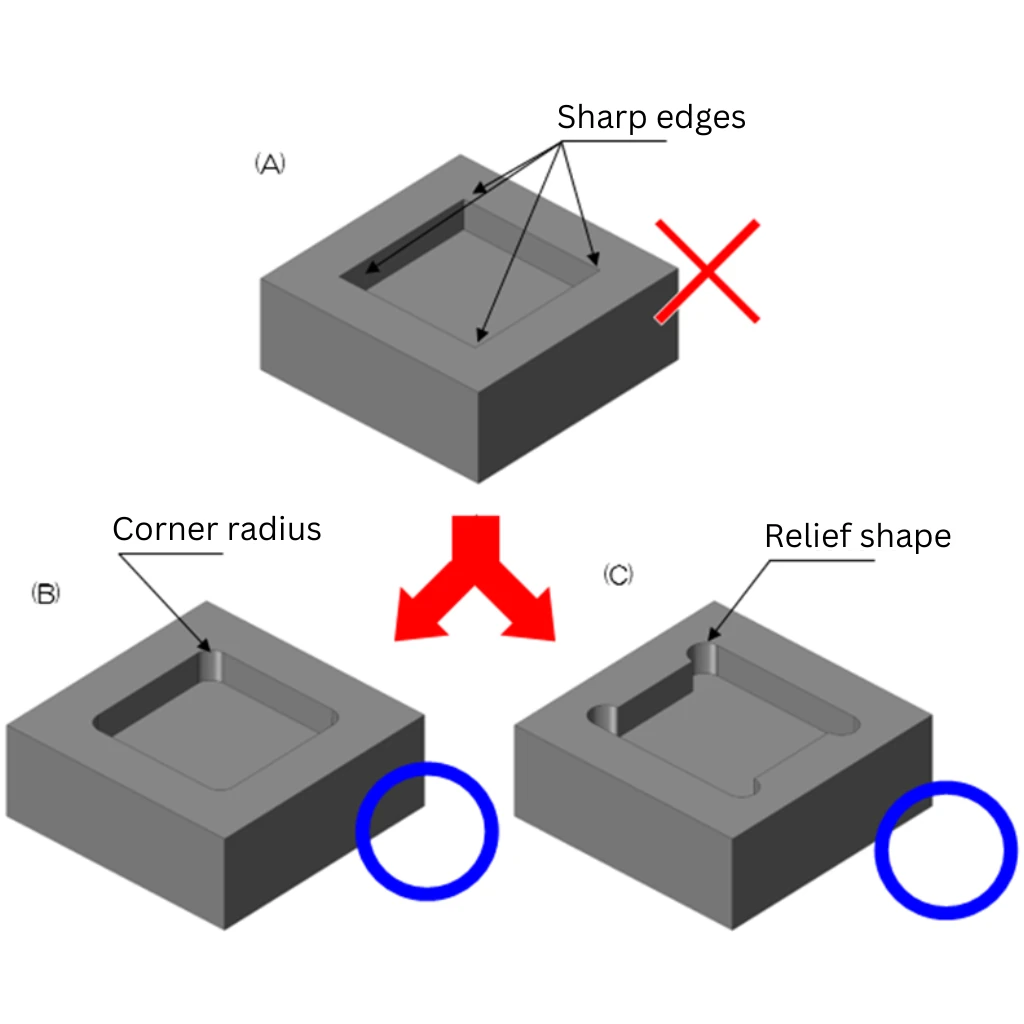
Internal Corner Radii:
Here's a fundamental reality of cnc milling components: end mills are cylindrical. They physically cannot create sharp 90-degree internal corners. Specifying sharp internal corners is one of the most common CNC design mistakes—and it immediately signals to machinists that you haven't considered manufacturability.
- Minimum internal radius: 0.005" (0.13mm)—but requires specialty tooling
- Recommended internal radius: 0.030" (0.76mm) or larger for standard tooling compatibility
- Deep pockets: Use radius at least 1/3 of the cavity depth
- Best practice: Specify 130% of your cutting tool's radius to reduce tool stress and increase cutting speed
According to Dadesin's CNC guide, for applications requiring sharp corners, T-bone undercuts (dogbones) provide an effective workaround. These specialized cuts create the appearance of sharper intersections while maintaining machinability.
Cavity and Pocket Depth:
Deep pockets create machining challenges due to tool limitations. When pocket depth exceeds three times the tool diameter, the extended cutting length reduces tool rigidity. This leads to vibration, poor surface finish, and potential tool breakage—especially visible as milling marks on your finished parts of a cnc mill operation.
- Standard depth limit: 3x the tool diameter (e.g., 0.5" end mill = 1.5" max depth)
- Deep cavities: Maximum 4x the pocket width with stepped designs
- Harder materials: Steel and titanium amplify depth limitations; consult your machinist
Hole Design Specifications:
Holes seem simple, but they're a frequent source of manufacturability issues. Non-standard hole sizes require end milling rather than drilling, increasing machining time by 3-5x. Thread specifications add another layer of complexity.
- Use standard drill sizes: Metric or imperial increments that match readily available bits
- Thread depth: Maximum 3x the hole diameter (strength resides in first few threads)
- Blind hole bottoms: Accept the natural 118° or 135° cone from drill bits—flat bottoms require secondary operations
- Thread engagement: Leave unthreaded length of 0.5x diameter at blind hole bottoms for tap clearance
- Wall clearance: Position tapped holes away from pocket walls to prevent breakout
Undercuts and Feature Accessibility:
Standard CNC cutting tools approach from above. Features that require tools to reach underneath or around obstacles—undercuts, T-slots, dovetails—demand specialized tooling and add significant cost. According to Dadesin, always provide at least 4x the undercut depth as clearance around the feature for proper tool movement.
- Avoid undercuts when possible: Redesign as multi-component assemblies if feasible
- Standard undercut widths: Use whole millimeter increments to avoid custom tooling
- Tool access: Ensure clear, direct paths for all cutting operations
- 5-axis consideration: Features at compound angles may justify higher machine costs to eliminate multiple setups
Designing Parts Your Machine Shop Will Thank You For
Beyond the technical specifications, certain design habits consistently create problems—even when individual features seem acceptable. Avoid these common CNC prototyping mistakes that experienced engineers still make:
Common Mistakes to Avoid:
- Over-tolerancing everything: Applying ±0.001" to every dimension when only mating surfaces need it—adds inspection time and cost without functional benefit
- Decorative complexity: Embossments, engravings, and aesthetic curves that serve no functional purpose but add hours of machining time
- Knife edges: Where two surfaces meet at acute angles, creating fragile features prone to damage during handling—add 0.005-0.015" fillets to outside edges
- Complex curves with varying radii: Organic shapes requiring multiple tool changes and extended programming—use consistent radii wherever function allows
- Cast-optimized geometries: Draft angles designed for casting create machining complications—create separate simplified versions for machined prototypes
- Ignoring material behavior: Specifying ultra-thin walls in materials prone to deflection or heat buildup during cutting
Material-Specific Considerations:
Different materials behave differently under cutting forces. When working with a cnc acrylic service, you'll need different design approaches than with aluminum or steel. Acrylic cnc machining requires careful attention to heat management—acrylic softens and can melt if cutting speeds are too aggressive or chip evacuation is poor.
Similarly, abs cnc machining presents unique challenges. ABS plastic is prone to melting and deformation during aggressive cuts. Design features with adequate chip clearance, and expect slightly looser tolerances than metals allow. For both plastic materials, increase minimum wall thicknesses to 1.5-2.0mm to prevent flexing during cutting operations.
Documentation That Prevents Confusion:
- Establish drawing precedence: Clearly indicate whether CAD models or 2D drawings take priority when conflicts exist
- Call out critical dimensions: Highlight the 3-5 dimensions that truly matter for function
- Specify thread class: Don't dictate drill sizes—let machinists optimize their process
- Note surface finish only where needed: Default 3.2 µm Ra works for most applications; specify smoother finishes only on functional surfaces
According to Modus Advanced, early manufacturing input during design phases identifies potential issues before they become costly problems. Engaging your machining partner during initial design iterations enables optimization for both function and manufacturability.
The bottom line? A few hours spent reviewing your design against these DFM principles can save days of rework and thousands in unnecessary machining costs. When your prototype arrives matching your expectations—on time and on budget—you'll appreciate the upfront investment in manufacturability analysis.
With your design optimized for efficient machining, the next critical phase is planning how your validated prototype transitions into production manufacturing—a process that requires its own strategic approach.
Transitioning from Prototype to Production Manufacturing
Your prototype works. Testing confirms the design meets functional requirements. Now what? The leap from a single validated prototype to volume manufacturing trips up even experienced engineering teams. Without a structured transition workflow, projects stall, costs spiral, and timelines extend indefinitely.
According to UPTIVE Manufacturing, even the best products face design challenges during this phase—the first iPhone went through dozens of iterations before its 2007 launch. The key difference between successful product launches and failed ones often comes down to how systematically teams manage the prototype-to-production journey.
Let's walk through the complete transition workflow with actionable steps, realistic timelines, and the validation checkpoints that separate prototype machined parts ready for production from those that need more refinement.
Validating Your Prototype Before Production Commitment
Before scaling up, you need confidence that your cnc rapid prototyping investment has delivered a genuinely production-ready design. Rushing this validation phase creates expensive problems downstream—tooling changes, production line modifications, and worst of all, field failures that damage customer relationships.
Here's the systematic validation sequence that prevents premature production commitment:
- Functional performance testing: Subject your prototype to real-world operating conditions. Measure actual performance against design specifications. Document any deviations and determine if they fall within acceptable limits.
- Fit and assembly verification: Test your prototype machined parts in the actual assembly context. Confirm mating surfaces align properly, fasteners engage correctly, and tolerance stack-ups don't create interference.
- Material property confirmation: Verify that the machined prototype's material properties match production requirements. Check hardness, tensile strength, and corrosion resistance if these factors affect performance.
- Environmental stress testing: Expose prototypes to temperature extremes, humidity, vibration, or other conditions they'll encounter in service. According to Ensinger, validating complex features early identifies potential issues before full production.
- Stakeholder review and approval: Present test results to engineering, quality, and business stakeholders. Gather feedback and confirm alignment before proceeding.
- Design freeze decision: Formally lock the design configuration. Any changes after this point require documented change control procedures.
What testing protocols should you implement? That depends on your application. Medical devices require biocompatibility testing and regulatory documentation. Automotive components need durability cycling and crash simulation. Consumer electronics demand drop testing and thermal cycling. Match your validation rigor to the consequences of field failure.
According to Fictiv's manufacturing experts, one of the hardest things to nail during prototyping is pricing. If you get cost estimates wrong at this stage, the entire program can go off the rails when production economics don't match projections.
Scaling from Single Prototype to Volume Manufacturing
Once validation confirms your design, the transition to production manufacturing follows a structured progression. Jumping directly from one prototype to thousands of units invites disaster. Instead, smart teams use intermediate steps to catch issues before they become catastrophically expensive.
Here's the complete scaling workflow for machining manufacturing transitions:
- Low-volume production run (10-100 units): Manufacture a small batch using production-intent processes. This reveals manufacturing variability, identifies bottlenecks, and validates quality control procedures. According to Fictiv, low-volume manufacturing acts as a crucial intermediary phase—a testing ground for both the product and the production process.
- Process capability analysis: Measure critical dimensions across the pilot batch. Calculate Cp and Cpk values to confirm the process consistently produces parts within specification. Target Cpk values of 1.33 or higher for production readiness.
- Bill of Materials finalization: Create the complete BOM including all components, materials, and quantities. This document guides manufacturing and ensures consistency across production runs.
- Quality control protocol establishment: Define inspection sampling plans, in-line testing requirements, and quality checkpoints. Set statistical process control limits based on pilot run data.
- Supply chain validation: Confirm material suppliers can meet volume requirements with consistent quality. Identify backup sources for critical components. According to UPTIVE, addressing potential supply chain disruptions early builds a frictionless production process long-term.
- Production ramp-up: Gradually increase volumes while monitoring quality metrics. Scale to full production only after demonstrating process stability at each intermediate volume level.
Timeline Expectations by Prototype Complexity:
How long should this transition actually take? Here's what realistic planning looks like for cnc machining and manufacturing projects:
| Prototype Complexity | Validation Phase | Low-Volume Run | Production Ramp | Total Timeline |
|---|---|---|---|---|
| Simple (single setup, standard materials) | 1-2 weeks | 1-2 weeks | 2-3 weeks | 4-7 weeks |
| Moderate (multi-setup, tight tolerances) | 2-4 weeks | 2-4 weeks | 4-6 weeks | 8-14 weeks |
| Complex (5-axis, exotic materials, assemblies) | 4-8 weeks | 4-6 weeks | 6-12 weeks | 14-26 weeks |
| Regulated (medical, aerospace certification) | 8-16 weeks | 6-12 weeks | 12-24 weeks | 26-52 weeks |
These timelines assume a validated design entering the transition phase. Add 2-4 weeks for each design iteration if prototype testing reveals issues requiring modifications. According to Ensinger, using an iterative approach—refining tolerances, geometries, and surface finishes as needed—reduces risk and shortens overall development timelines.
Production Readiness Criteria Checklist:
Before committing to full-scale production, confirm these criteria are satisfied:
- Design freeze completed with formal change control in place
- All functional and environmental tests passed with documented results
- Process capability (Cpk ≥ 1.33) demonstrated on critical dimensions
- Quality control procedures documented and validated
- Supply chain confirmed for volume requirements with backup sources identified
- Cost model validated against actual low-volume production data
- Manufacturing partner qualified with appropriate certifications (ISO 9001, industry-specific standards)
Working with the right prototype machine shop from the start streamlines this entire transition. Partners experienced in both rapid prototyping and volume production understand the nuances of scaling—they've seen the common failure modes and know how to prevent them. According to UPTIVE, selecting a partner with relevant experience can potentially save thousands of dollars because they're familiar with common pitfalls and effective ways to steer clear of them.
The transition from prototype to production isn't just a manufacturing challenge—it's a project management discipline. Teams that follow structured workflows, validate at each stage, and resist the pressure to skip steps consistently deliver successful products. Those that rush the process often find themselves back at the prototype stage, having wasted time and money learning expensive lessons.
With your transition workflow mapped out, the next consideration is how industry-specific requirements shape your prototyping approach—because automotive, aerospace, and medical applications each demand unique validation standards and quality certifications.
Industry-Specific CNC Prototyping Applications
Your transition workflow is mapped. Your design follows DFM principles. But here's what separates successful prototyping projects from costly failures: understanding that aerospace prototypes, automotive components, and medical devices each operate under entirely different rules. The tolerances that satisfy one industry may fall dangerously short in another.
When you're searching for cnc machining near me or evaluating metal fabricators near me, industry-specific expertise matters far more than proximity alone. A shop that excels at consumer electronics enclosures may struggle with the documentation requirements of aerospace work. Let's examine what each major industry demands—and how to find partners equipped to deliver.
Automotive Prototype Requirements and Validation Standards
Automotive prototyping operates at the intersection of precision engineering and rigorous quality systems. According to American Micro Industries, the automotive industry demands consistent, defect-free parts, and IATF 16949 is the global standard for automotive quality management—combining ISO 9001 principles with sector-specific requirements for continuous improvement, defect prevention, and stringent supplier oversight.
What makes automotive prototyping unique? The stakes extend beyond individual part performance. A failed prototype can delay entire vehicle programs, affecting thousands of dependent components and suppliers. Whether you're developing chassis assemblies, suspension components, or precision metal bushings, your prototyping partner's quality systems directly impact your development timeline.
Critical requirements for automotive CNC prototypes:
- IATF 16949 certification: Demonstrates the facility has discipline and capability to meet automotive quality expectations—this certification is non-negotiable for Tier 1 suppliers
- Statistical Process Control (SPC): Continuous monitoring of critical dimensions throughout production, catching trends before they create out-of-spec parts
- PPAP documentation capability: Production Part Approval Process paperwork required before any component enters vehicle production
- Material traceability: Complete documentation from raw material certification through finished part—essential for recall management
- Rapid iteration capability: Lead times as fast as one working day accelerate development cycles when design changes require quick validation
For automotive applications, metal cnc machining partners like Shaoyi Metal Technology demonstrate the quality infrastructure that automotive OEMs require. Their IATF 16949 certification and strict SPC implementation ensure high-tolerance components meet automotive-grade standards—whether you need complex chassis assemblies or custom precision parts. With lead times as fast as one working day, development cycles don't stall waiting for prototype validation.
Steel sheet metal components for body structures, aluminum sheet metal for weight-sensitive applications, and precision-machined drivetrain components all require this level of quality system maturity. When evaluating automotive prototyping partners, certification isn't just a nice-to-have—it's the minimum entry requirement.
Industry-Specific Material and Tolerance Demands
Beyond automotive, aerospace and medical device prototyping impose their own distinct requirements. Understanding these differences prevents costly mistakes when your project crosses industry boundaries.
Aerospace Prototyping Requirements:
According to American Micro Industries, the aerospace sector imposes some of the most rigorous compliance standards in manufacturing. AS9100 certification extends ISO 9001 requirements with aerospace-specific controls and traceability mandates.
- AS9100 certification: The baseline quality standard for aerospace suppliers—mandatory for most programs
- NADCAP accreditation: Required for special processes like heat treating, chemical processing, and nondestructive testing
- Material certifications: Mill test reports required for every raw material lot; no substitutions permitted
- First Article Inspection (FAI): Comprehensive dimensional verification per AS9102 before production release
- Tolerance expectations: Typically ±0.0005" to ±0.001" on critical flight-safety dimensions
- Surface finish specifications: Often 32 µin Ra or better to prevent stress concentrations
According to Avanti Engineering, certifications like ISO 9001 or AS9100 indicate a commitment to consistent quality and reliable processes—essential indicators when evaluating aerospace prototyping capabilities.
Medical Device Prototyping Requirements:
Medical device manufacturing falls under FDA regulatory oversight, creating documentation and validation requirements that exceed other industries. According to American Micro Industries, facilities must follow FDA 21 CFR Part 820 (Quality System Regulation) governing product design, manufacturing, and tracking.
- ISO 13485 certification: The definitive quality management standard for medical devices, outlining strict controls over design, manufacturing, traceability, and risk mitigation
- Biocompatibility considerations: Material selection impacts patient safety—prototypes must use production-equivalent materials for meaningful testing
- Cleanroom machining: Some implantable devices require contamination-controlled environments
- Complete traceability: Every material lot, process parameter, and inspection result documented for regulatory submission
- Validation protocols: IQ/OQ/PQ documentation demonstrating process capability
- Tolerance requirements: Surgical instruments often demand ±0.0002" on cutting edges and mating surfaces
According to GMI Corporation's 2025 trends report, medical device manufacturing continues seeing increased growth within sophisticated surgical procedures, driving demand for CNC machining partners capable of producing intricate parts that are difficult to machine with traditional methods.
Defense and Government Prototyping:
Defense-related machining adds security requirements beyond quality certifications. According to American Micro Industries, defense contractors require ITAR registration with the U.S. Department of State and information security protocols to handle sensitive technical data.
- ITAR compliance: Mandatory registration for any work involving defense articles or technical data
- Cybersecurity requirements: NIST 800-171 compliance for handling Controlled Unclassified Information (CUI)
- Quality standards: Typically ISO 9001 or AS9100 plus program-specific requirements
- Security clearances: Personnel handling classified projects require appropriate clearance levels
Comparative Industry Requirements:
| Requirement | Automotive | Aerospace | Medical Device | Defense |
|---|---|---|---|---|
| Primary Certification | IATF 16949 | AS9100 | ISO 13485 | ISO 9001 + ITAR |
| Typical Tolerance | ±0.001" to ±0.005" | ±0.0005" to ±0.001" | ±0.0002" to ±0.001" | ±0.001" to ±0.005" |
| Documentation Level | PPAP packages | FAI per AS9102 | DHF/DMR records | Program-specific |
| Special Processes | Heat treatment, plating | NADCAP-accredited | Passivation, cleaning | Per MIL-SPEC |
| Material Requirements | OEM-approved specs | AMS/MIL materials | Biocompatible grades | MIL-SPEC materials |
| Traceability | Lot-level | Serial number | Unit-level | Program-dependent |
When evaluating cnc machine shops near me for industry-specific work, certification status is your first filter. According to Avanti Engineering, look for partners with documented evidence of successful projects in your specific industry—certifications demonstrate capability, but experience proves execution.
Sheet metal fabrication and aluminum sheet metal components often serve across multiple industries, but the quality system requirements differ dramatically. A bracket that's acceptable for consumer products may require completely different documentation, inspection protocols, and traceability for aerospace or medical applications—even if the geometry and tolerances remain identical.
The bottom line? Industry expertise isn't optional. When your prototype needs to meet automotive validation standards, aerospace flight-safety requirements, or medical device regulatory submissions, your manufacturing partner's quality systems become as important as their machining capabilities. Choose partners whose certifications match your industry's demands, and you'll avoid the painful discovery that great parts without proper documentation are worthless for your application.
With industry-specific requirements understood, the final piece of the puzzle is selecting a prototyping partner capable of meeting your unique combination of technical and quality system demands—a decision that shapes your entire development experience.
Selecting the Right CNC Prototyping Partner
You've mastered design for manufacturability, understand tolerance specifications, and know exactly what your industry demands. Now comes the decision that ties everything together: choosing the right cnc prototyping service to transform your designs into reality. The wrong partner means missed deadlines, quality issues, and frustrating communication breakdowns. The right one becomes an extension of your engineering team.
According to Sanshi Aerotech, expertise and experience should be your top priorities when evaluating partners. Aim to work with companies that have a proven track record in your specific industry—a partner experienced in aerospace machining handles tight tolerances of ±0.005" routinely, while automotive-focused shops excel at high-volume production runs with certified quality systems.
But how do you separate genuinely capable prototype machining services from those that simply talk a good game? Let's break down the evaluation criteria that matter most.
Evaluating CNC Prototyping Partners for Your Project
When you need cnc prototypes that perform exactly like production parts, your partner selection checklist should cover technical capability, quality systems, communication practices, and scaling potential. Here's what to prioritize:
- Shaoyi Metal Technology (Automotive Focus): IATF 16949 certified with strict Statistical Process Control, offering lead times as fast as one working day. Their seamless scaling from rapid prototyping to mass production makes them ideal for automotive chassis assemblies, precision components, and custom metal parts requiring high-tolerance machining.
- Technical Capability Assessment: Verify they have the right equipment for your project—5-axis machines for complex geometries, appropriate material experience, and surface finishing capabilities matching your specifications
- Industry Certifications: Match certifications to your requirements—ISO 9001 as baseline, IATF 16949 for automotive, AS9100 for aerospace, ISO 13485 for medical devices
- Quality Verification Systems: Look for documented inspection protocols, CMM capabilities, and statistical process control implementation
- Communication Infrastructure: Evaluate responsiveness during the quoting phase—partners who respond slowly before winning your business rarely improve afterward
- DFM Analysis Offering: The best partners provide manufacturability feedback before quoting, helping you optimize designs for cost and quality
- Production Scaling Capability: Confirm they can handle both rapid cnc prototyping and volume manufacturing without requiring you to find a new supplier
According to Modus Advanced, a custom manufacturing partner should have substantial engineering resources on staff. Look for partners with engineers making up at least 10% of their workforce—this demonstrates a commitment to technical excellence rather than just production capability. These engineers should be actively involved in customer projects, providing direct access for technical discussions.
Quality verification goes beyond certifications. According to Sanshi Aerotech, ask about specific quality control measures and testing protocols. A partner with strong commitment to quality employs routine inspections and measurements using high-precision tools like coordinate measuring machines (CMM) to ensure every component meets exact specifications.
Questions to ask potential online cnc machining services:
- What is your typical turnaround time for rapid cnc prototyping projects similar to mine?
- Can you share examples of similar projects you've completed in my industry?
- How do you handle design changes mid-project?
- What inspection documentation do you provide with delivered parts?
- Do you offer DFM analysis before finalizing quotes?
- What's your process for transitioning successful prototypes to production volumes?
According to Modus Advanced, vertical integration represents a partner's ability to handle multiple processes in-house rather than outsourcing to subcontractors. This approach offers significant advantages: single-source accountability, reduced lead times, better quality control across operations, and simplified communication. When evaluating partners, ask them to map their capabilities against your typical part requirements.
Getting Started with Your First Prototype Order
Ready to move forward? Here's how to set your first project up for success with any rapid cnc prototyping partner.
Prepare your files properly:
- Export CAD models in STEP or IGES format for universal compatibility
- Include 2D drawings with critical dimensions, tolerances, and surface finish callouts
- Specify material grade completely (e.g., "Aluminum 6061-T6" not just "aluminum")
- Identify which dimensions are critical versus standard tolerance
- Note any special requirements: certifications needed, inspection documentation, surface treatments
Set clear expectations upfront:
According to LS Rapid Prototyping, a complete and clean set of information is necessary for accurate quotes. A quotation request with comprehensive information requires fewer rounds of clarification, avoids unforeseen expenses, and allows service providers to accurately evaluate your project.
- Communicate your timeline requirements honestly—rush jobs cost more, but partners appreciate knowing upfront
- Discuss quantity flexibility if you might need additional iterations
- Clarify inspection requirements before production begins
- Establish communication preferences and primary contacts on both sides
Leverage the DFM process:
According to LS Rapid Prototyping, professional DFM analysis isn't an afterthought—it's an investment that reduces total cost and delivery time. A professional design for manufacturability analysis will identify potential issues affecting production and fast-track your path from file to finished part. Partners offering free DFM feedback translate design intent into machinable blueprints, preventing costly misunderstandings.
The best cnc prototyping service relationships evolve beyond transactional interactions to become strategic partnerships. According to Modus Advanced, signs of a potential strategic partner include proactive engineering recommendations, investment in understanding your product requirements, and capabilities that can scale with your growth from prototype validation through volume production.
Your next step is simple: Take your prepared CAD files and documentation, reach out to qualified partners matching your industry requirements, and request quotes with DFM analysis. For automotive applications requiring certified quality systems and rapid turnaround, Shaoyi Metal Technology's automotive machining capabilities demonstrate what to look for in a production-ready partner—IATF 16949 certification, high-tolerance machining, and the ability to scale seamlessly from single prototypes to volume manufacturing.
The journey from CAD file to production-ready parts doesn't have to be complicated. With the right partner, clear communication, and properly prepared files, your cnc prototypes arrive on time, meet specifications, and provide the validation data you need to move confidently toward production. That's the real value of selecting a prototyping partner who understands both your immediate needs and your long-term manufacturing goals.
Frequently Asked Questions About CNC Machining Prototyping
1. What is a CNC prototype?
A CNC prototype is a functional part created using computer-controlled cutting tools that remove material from solid blocks of metal or plastic. Unlike 3D printing which builds layer by layer, CNC prototyping is subtractive manufacturing that delivers production-grade components with identical material properties to final parts. This process combines rapid prototyping speed with the precision of traditional machining, achieving tolerances as tight as ±0.001 inches. CNC prototypes are ideal for design validation, fit testing, and functional performance evaluation before committing to full-scale production.
2. How much does a CNC prototype cost?
CNC prototype costs typically range from $100 to $1,000+ per part depending on several factors. Simple aluminum brackets start around $150-200, while complex multi-axis titanium components can exceed $1,000. Key cost drivers include material selection (titanium costs 8-10x more than aluminum), machining complexity, tolerance requirements, surface finish specifications, and quantity ordered. Setup and programming represent fixed costs that spread across larger orders, making batch ordering 70-90% cheaper per unit. Rush lead times can add 25-100% to standard pricing.
3. What tolerances can CNC prototyping achieve?
Standard CNC machining achieves tolerances of ±0.005 inches (0.127mm), which satisfies most prototype applications. Precision work reaches ±0.001 inches (0.025mm) for mating components and bearing fits. High-precision aerospace and medical applications can achieve ±0.0005 inches or tighter with specialized equipment and controlled environments. Material selection affects achievable tolerances—metals hold tighter specs than plastics due to deflection under cutting forces. Only specify tight tolerances on critical features, as precision requirements exponentially increase costs through slower machining speeds and advanced inspection.
4. How long does CNC prototype machining take?
CNC prototype lead times range from 1 day for simple parts to 2-3 weeks for complex components. Many shops offer expedited services with turnaround as fast as one working day for urgent projects. Standard timelines typically run 5-10 business days including programming, machining, and quality inspection. Factors affecting lead time include part complexity, material availability, tolerance requirements, surface finishing needs, and current shop capacity. Proper file preparation with complete specifications prevents delays from clarification rounds and design revisions.
5. When should I choose CNC machining over 3D printing for prototypes?
Choose CNC machining when you need production-grade material properties, tight tolerances below ±0.005 inches, superior surface finishes, or structural testing under real operating conditions. CNC excels for functional prototypes in metals like aluminum, steel, and titanium where material integrity matters. Select 3D printing for visual models, complex internal geometries, organic shapes, or early-stage design iteration where speed trumps precision. Many successful projects combine both methods—using 3D printing for rapid design exploration and CNC for final functional validation with production materials.