 Small batches, high standards. Our rapid prototyping service makes validation faster and easier —

CNC Machine Parts Decoded: From Spindle To Servo In One Deep Dive
Understanding CNC Machine Parts and Their Role in Precision Manufacturing
Ever wondered what transforms a block of raw metal into a perfectly machined aerospace component? The answer lies in the intricate symphony of CNC machine parts working together with remarkable precision. These components form the backbone of modern manufacturing, enabling factories worldwide to produce everything from medical implants to automotive engines with consistency that manual machining simply cannot match.
What Makes CNC Machines Tick
At its core, a CNC (Computer Numerical Control) machine is an assembly of interconnected mechanical, electrical, and control components designed to execute precision tasks automatically. Unlike traditional manual machines, these sophisticated systems follow coded instructions to perform operations with exceptional accuracy and repeatability. The parts of a CNC machine work in harmony, each playing a specific role in translating digital designs into physical reality.
Think of it this way: when you examine the parts of a machine like a CNC mill or lathe, you're looking at three primary systems working together. First, there's the structural framework that provides stability. Second, you have the motion control components that enable precise movement along multiple axes. Third, the control systems interpret programming commands and coordinate every action. Each cnc parts category depends on the others to function correctly.
The quality of individual CNC machine parts directly determines machining accuracy, surface finish quality, and overall production efficiency. Even a single worn bearing or misaligned guide can cascade into dimensional errors across thousands of manufactured pieces.
The Building Blocks of Precision Manufacturing
Understanding cnc machined components begins with recognizing their diversity. Spindles rotate cutting tools at thousands of RPMs. Ball screws convert rotational motion into linear movement with micron-level precision. Servo motors respond to control signals in milliseconds. Encoders provide real-time position feedback. Together, these machine and parts create a closed-loop system capable of holding tolerances that were unimaginable just decades ago.
What makes this technology particularly valuable is its versatility. According to Clausing Industrial, CNC machines serve industries ranging from automotive to aerospace, medical device manufacturing to consumer electronics. Each application demands specific component configurations, but the fundamental principles remain consistent across all platforms.
Throughout this comprehensive guide, you'll discover how each component category contributes to the overall machining process. From the rigid machine bed that dampens vibrations to the sophisticated control panels that operators interact with daily, every element plays an essential role. By the time you finish reading, you'll understand not only what these components do but also how to identify wear signs, plan maintenance, and source quality replacements when needed.
Machine Bed and Frame Components That Ensure Stability
Imagine trying to write with a pen on a wobbly table. No matter how skilled you are, the instability will show in your handwriting. The same principle applies to CNC machining. The machine bed and frame serve as the foundation upon which all precision depends. Without rock-solid structural cnc machine components, even the most advanced spindles and control systems cannot deliver accurate results.
Frame and Bed Construction Materials
When you examine the parts of machines used in CNC applications, you'll notice that manufacturers carefully select bed materials based on specific performance requirements. According to WMTCNC, the machine bed must be robust and stable enough to support guide rails, headstocks, and other critical manufacturing machine parts while maintaining precision over years of operation.
Three primary materials dominate CNC machine bed construction:
- Grey Cast Iron: This remains the most prevalent choice for CNC machine beds. It offers exceptional thermal stability and high rigidity, which reduces bed deformation during extended machining operations. Cast iron's natural vibration-dampening properties make it ideal for precision work.
- Polymer Concrete (Engineered Granite): This material delivers outstanding thermal stability, maintaining bed integrity even under elevated temperatures. It prevents thermal expansion from compromising machining accuracy, making it popular for high-precision applications.
- Welded Steel Structures: Steel beds provide formidable rigidity and load-bearing capacity, suitable for heavy-duty machining operations. However, their inferior thermal stability compared to cast iron requires additional design considerations to mitigate thermal deformation effects.
Each part of a machine's frame must sustain high accuracy and positioning precision over extended periods. This is why manufacturers like WMTCNC consistently use casting beds to guarantee lathe precision throughout the machine's operational life.
How Structural Rigidity Affects Accuracy
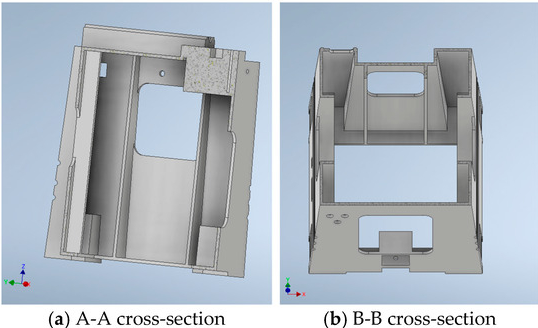
Why does rigidity matter so much? During machining, cutting forces generate vibrations that can transfer through the entire machine structure. If the bed flexes or resonates, these vibrations appear as surface finish imperfections or dimensional inaccuracies on your workpiece. The bed structure typically features a closed box-shaped design with strategically arranged ribs to combat this issue.
The arrangement of internal ribs significantly impacts performance. Longitudinal ribs improve bending and torsional rigidity, while diagonally inclined and intersecting ribs are particularly effective at increasing overall stiffness. For CNC lathes, the cross-sectional shape often adopts a closed box structure that increases the outer contour size, providing high bending and torsional rigidity while improving chip evacuation conditions.
Different CNC machine types have distinct structural requirements based on their operational demands. CNC router parts, for instance, often utilize lighter frame constructions since routers typically work with softer materials like plastics, wood, and aluminum. In contrast, milling machines and lathes require substantially heavier cnc components to handle the forces generated when cutting steel and other hard metals.
| CNC Machine Type | Typical Bed Material | Frame Configuration | Primary Structural Priority |
|---|---|---|---|
| CNC Mill / Machining Center | Grey Cast Iron | Fixed or Mobile Column, T-shaped bed | Maximum rigidity for hard material cutting |
| CNC Lathe | Grey Cast Iron | Slant or Flat Bed with closed box section | Torsional stiffness and chip evacuation |
| CNC Router | Welded Steel or Aluminum | Gantry-style open frame | Large work envelope with moderate rigidity |
As noted by Rex Plastics, CNC routers work with flat sheet stock and softer materials, which explains their lighter construction compared to mills designed for block materials and harder metals. Understanding these structural differences helps you appreciate why certain machines excel at specific applications while others struggle.
Thermal stability presents another critical consideration. During operation, heat generated by motors, spindles, and cutting processes can cause thermal expansion in structural components. Grey cast iron and engineered granite minimize this effect, while steel structures may require cooling systems or compensation algorithms to maintain accuracy. This is precisely why high-precision machines often incorporate temperature sensors throughout their frames to monitor and compensate for thermal changes in real-time.
With the foundation covered, the next logical step is exploring what sits atop this stable platform: the spindle systems that actually perform the cutting work.
Spindle Systems and Their Critical Performance Parameters
If the machine bed is the foundation, then the spindle is undoubtedly the heart of any CNC machine. This rotating assembly holds and drives cutting tools at precisely controlled speeds, directly determining what materials you can machine and how fine a surface finish you can achieve. Understanding spindle parts and their specifications empowers you to make informed decisions about machine capabilities, maintenance timing, and component replacements.
Spindle Motor and Bearing Systems
What exactly happens inside a milling spindle when you press that start button? The spindle motor converts electrical energy into rotational motion, which transfers through bearings to the tool holder and ultimately to your cutting tool. Every component in this chain affects performance, and understanding their roles helps you identify potential issues before they become costly problems.
The milling machine spindle relies on precision bearings to maintain rotational accuracy while supporting both radial and axial loads. Angular contact ball bearings are the most common choice for high-speed applications, typically arranged in pairs or sets to handle forces from multiple directions. These bearings must maintain extremely tight tolerances, often measured in microns, to prevent runout that would transfer directly to your workpiece.
When evaluating spindle specifications, three parameters demand your attention:
- RPM Range: This determines what materials and tool sizes you can effectively use. High-speed spindles reaching 24,000 RPM or higher excel at small-diameter tools and aluminum machining, while lower-speed, high-torque spindles better suit large cutters and hard materials like steel.
- Power Rating (kW/HP): This indicates how much material removal force the spindle can sustain. A 15kW spindle handles aggressive roughing operations that would stall a 7.5kW unit. Match power ratings to your typical workload rather than occasional extreme demands.
- Runout Tolerance: Measured in microns (thousandths of a millimeter), runout indicates how much the spindle nose deviates from perfect concentricity during rotation. Quality spindles maintain runout below 5 microns, with high-precision units achieving 2 microns or less. Higher runout accelerates tool wear and degrades surface finish.
The bearing preload setting also significantly impacts performance. Too little preload allows excessive play, causing chatter and poor surface finish. Too much preload generates excessive heat, accelerating bearing wear and potentially causing premature failure. Manufacturers carefully calibrate this balance during assembly, and maintaining proper lubrication helps preserve it throughout the spindle's service life.
Belt-Driven vs Direct-Drive Configurations
Ever noticed how some machines sound distinctly different during operation? The spindle drive configuration often explains this. CNC machines employ two primary methods to transfer motor power to the spindle: belt-driven systems using a spindle pulley arrangement and direct-drive configurations where the motor and spindle share a common shaft.
Belt-driven spindles use a gearbox pulley or machining pulley system that connects the motor to the spindle through timing belts or V-belts. This configuration offers several advantages. The motor sits separately from the spindle, reducing heat transfer to the cutting zone. Belt systems also provide some vibration isolation between motor and spindle. Additionally, changing pulley ratios allows manufacturers to offer different speed-torque characteristics without redesigning the entire spindle assembly.
However, belt-driven systems introduce potential maintenance points. Belts stretch over time, requiring periodic tension adjustment. Pulley alignment must remain precise to prevent premature belt wear and vibration. The gearbox pulley mechanism, while robust, adds components that eventually require service or replacement.
Direct-drive spindles eliminate the mechanical connection between motor and spindle by integrating them into a single unit. The motor rotor mounts directly on the spindle shaft, creating an extremely rigid connection with zero backlash. This configuration excels in high-speed applications where belt limitations would otherwise restrict performance. Many modern machining centers use direct-drive spindles capable of 15,000 to 40,000 RPM.
The trade-off? Direct-drive spindles transfer motor heat directly into the spindle assembly, requiring sophisticated cooling systems to maintain thermal stability. They also typically cost more to manufacture and repair than their belt-driven counterparts. When a direct-drive spindle fails, you're often replacing the entire motor-spindle unit rather than individual components.
Key Spindle Maintenance Indicators
How do you know when spindle parts need attention before a catastrophic failure ruins your workpiece or damages the machine? Experienced machinists learn to recognize subtle warning signs that indicate developing problems. Catching issues early often means the difference between a bearing replacement and a complete spindle rebuild.
Watch for these warning signs during regular operation:
- Unusual noise patterns: Grinding, squealing, or rumbling sounds during rotation often indicate bearing wear or contamination. A healthy spindle produces consistent, smooth sound at all speeds.
- Increased vibration: Use vibration monitoring equipment or simply touch the spindle housing during operation. Noticeable increases in vibration suggest bearing degradation, imbalance, or loosening components.
- Temperature rise: Bearings running hotter than normal indicate inadequate lubrication, excessive preload, or developing wear. Many machines include thermal sensors that trigger warnings when spindle temperature exceeds safe limits.
- Degraded surface finish: When parts that previously machined smoothly start showing chatter marks or rougher surfaces, spindle runout may have increased beyond acceptable limits.
- Dimensional inconsistency: Holes that should be perfectly round becoming slightly oval, or features drifting from nominal dimensions, can indicate spindle bearing wear affecting positioning accuracy.
- Visible contamination: Oil leaks around spindle seals, metal particles in coolant, or discoloration near bearings all warrant immediate investigation.
Preventive maintenance dramatically extends spindle life. This includes maintaining proper lubrication levels and quality, avoiding cold starts at high RPM, allowing adequate warm-up time before demanding operations, and keeping the machine environment clean to prevent contamination from entering bearing seals.
Understanding your spindle's capabilities and limitations sets the stage for the next critical system: the motion control components that position that spinning tool with micron-level precision across your workpiece.
Motion Control Components for Precise Axis Movement
You've got a powerful spindle spinning at thousands of RPM, but how does it get to exactly the right spot on your workpiece? This is where motion control components take center stage. These precision elements translate rotational motor output into linear axis movement with accuracy measured in microns. Without properly functioning ball screws, linear guides, servo motors, and encoders, even the most rigid machine frame and capable spindle cannot produce accurate parts.
Ball Screws and Linear Guide Systems
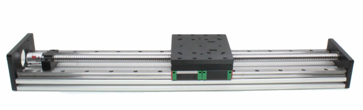
Imagine trying to push a heavy table across a room using a threaded rod. Now imagine that same motion, but smoother than silk and accurate to within a few thousandths of a millimeter. That's essentially what ball screws accomplish in CNC machines. These mechanical marvels convert rotational motion from servo motors into precise linear movement along each axis.
A ball screw assembly consists of a threaded shaft and a nut containing recirculating ball bearings. Unlike conventional lead screws where threads slide against each other, ball screws use rolling contact. The balls roll between the screw shaft and nut threads, dramatically reducing friction and virtually eliminating backlash when properly preloaded. This design enables positioning accuracies that sliding-contact systems simply cannot match.
The ball screw bearing arrangement at each end of the screw shaft plays a critical role in overall system accuracy. These support bearings must handle both radial loads and the thrust forces generated during machining operations. Typically, angular contact bearings in back-to-back or face-to-face configurations provide the necessary rigidity while accommodating thermal expansion. A worn or improperly installed ball screw bearing immediately translates into positioning errors and reduced repeatability.
Linear guides complement ball screws by constraining motion to a single axis while supporting the weight of moving components. Modern CNC machines predominantly use linear ball guides (also called linear motion guides or profile rails) rather than traditional dovetail slideways. These guides feature precision-ground rails with recirculating ball or roller bearings in the carriage blocks. The result? Smooth motion with minimal friction, high load capacity, and excellent geometric accuracy over the full travel range.
Several factors affect linear guide performance:
- Preload class: Higher preload increases rigidity but also increases friction and heat generation. Manufacturers select preload based on the balance between precision requirements and thermal considerations.
- Accuracy grade: Guides are manufactured to different precision classes, with tighter tolerances commanding higher prices but delivering better positioning accuracy.
- Lubrication: Proper lubrication prevents premature wear and maintains smooth operation. Many modern guides include automatic lubrication ports connected to the machine's central lubrication system.
- Contamination protection: Seals and wipers prevent chips and coolant from entering the bearing raceways, where they would cause rapid wear and accuracy degradation.
Servo Motors and Encoder Feedback Loops
What actually makes those ball screws rotate with such precise control? Servo motors provide the muscle, while encoders supply the intelligence. Together with the servo amplifier (sometimes called a servo amp), these components form a closed-loop control system that continuously monitors and corrects axis position in real-time.
A servo motor differs fundamentally from a standard electric motor. While conventional motors simply spin when powered, servo motors respond to command signals with precisely controlled rotation. The dc motor encoder mounted on the motor shaft continuously reports the exact rotational position back to the control system. This feedback enables the machine to know exactly where each axis is positioned at any given moment.
Here's how the closed-loop system works: The CNC controller sends a position command to the servo amplifier, which converts this signal into the appropriate current to drive the motor. As the motor rotates, the encoder generates pulses that represent incremental position changes. The servo amp compares the actual position (from encoder feedback) against the commanded position and makes continuous adjustments to eliminate any error. This happens thousands of times per second, enabling the smooth, accurate motion CNC machines are known for.
The servo amplifier serves as the critical link between the controller's low-power command signals and the motor's power requirements. Modern servo amplifiers use sophisticated algorithms to optimize motor response, minimize following error, and prevent oscillation. Some advanced systems incorporate vector drive technology, which provides superior torque control and efficiency by precisely managing the motor's magnetic field orientation. Adequate cooling is essential for these power electronics, which is why many systems include a dedicated drive fan to prevent thermal issues during demanding operations.
Encoder resolution directly impacts achievable positioning accuracy. Higher resolution encoders generate more pulses per revolution, enabling finer position discrimination. However, resolution alone doesn't guarantee accuracy; the encoder's precision and the overall system calibration matter equally.
| Precision Level | Typical Application | Servo Motor Power Range | Encoder Resolution | Positioning Accuracy |
|---|---|---|---|---|
| Standard | General machining, prototyping | 1-3 kW | 2,500-5,000 PPR | ±0.01 mm (±0.0004") |
| High Precision | Mold making, aerospace components | 2-5 kW | 10,000-17,000 PPR | ±0.005 mm (±0.0002") |
| Ultra Precision | Optical components, medical devices | 3-7 kW | 1,000,000+ counts/rev (absolute) | ±0.001 mm (±0.00004") |
Notice how encoder resolution requirements increase dramatically as precision demands rise. Standard machining might use incremental encoders with a few thousand pulses per revolution, while ultra-precision applications often employ absolute encoders with millions of counts per revolution. Absolute encoders offer an additional advantage: they maintain position knowledge even after power loss, eliminating the need for homing routines after each startup.
The interaction between these motion control components creates a system where each element depends on the others. A high-resolution encoder paired with a sluggish servo amp cannot achieve its potential accuracy. Similarly, a powerful servo motor driving a worn ball screw with excessive backlash will produce inconsistent results regardless of control system quality. This interdependence explains why experienced technicians evaluate the entire motion system when troubleshooting positioning problems rather than focusing on individual components.
Proper tuning of the servo system parameters—including proportional gain, integral gain, and derivative gain (PID settings)—significantly impacts machine performance. Under-tuned systems respond slowly and may exhibit following errors during rapid movements. Over-tuned systems can oscillate or produce jerky motion. Many modern controllers include auto-tuning features that simplify this process, but manual refinement often achieves superior results for demanding applications.
With precise motion control established, the next essential element is the interface that allows operators to command and monitor these sophisticated systems: the control panel and CNC controller.
Control Systems and Operator Interface Components
You've got precision motion control, a powerful spindle, and a rock-solid frame. But how do you actually tell the machine what to do? This is where the control panel cnc and controller unit become your primary interface with all that sophisticated hardware. Think of the control panel as the brain of the CNC machine, translating your intentions into coordinated movements that produce finished parts. Without understanding this critical interface, even the most capable machine remains just an expensive piece of metal.
Control Panel Functions and Operator Interface
When you approach a cnc machine panel for the first time, the array of buttons, switches, and screens can seem overwhelming. However, according to YEU-LIAN, a leading control panel manufacturer, understanding the basic layout and functions transforms this apparent complexity into an intuitive workspace. Every element serves a specific purpose in connecting you to the machine's capabilities.
The typical cnc milling machine control panel combines physical buttons for immediate machine control with a digital display screen for program visualization and parameter adjustment. This hybrid approach gives operators tactile feedback for critical functions while providing the flexibility of software-based interfaces for more complex operations.
What functions will you find on a well-designed control panel? Here are the essential elements:
- Power on/off key: Controls the main power supply to the machine, initiating startup sequences and shutdown procedures.
- Display screen: Shows current parameters, program code, axis positions, spindle speed, feed rates, and diagnostic information in real-time.
- Mode selection switches: Allow switching between manual operation, MDI (Manual Data Input), memory mode for running stored programs, and edit mode for program modifications.
- Jog keys: Enable manual movement of individual axes for setup operations, tool changes, and positioning before automatic cycles.
- Feed rate and spindle speed overrides: Rotary switches that let operators adjust programmed speeds in real-time, typically from 0% to 150% of programmed values.
- Cycle start and feed hold buttons: Control program execution, allowing operators to start, pause, and resume machining operations.
- Emergency stop (E-stop): A large, clearly marked button that immediately halts all machine motion and cuts power to drives when pressed. This is your ultimate safety control.
- Coolant controls: Activate and deactivate coolant flow during machining operations.
- MPG (Manual Pulse Generator): A handwheel that provides precise manual axis movement, often used during setup and fine adjustments.
- Alphanumeric keypad: Allows direct entry of coordinates, program codes, and parameter values.
Beyond the visible panel components, internal elements handle the actual signal processing. These include the breakout board, I/O boards for input/output signal management, PLC (Programmable Logic Controller) for sequence control, and power supply systems. The PLC deserves special mention because it manages the logical operations that coordinate multiple machine functions simultaneously, such as ensuring the spindle is running before allowing a feed move.
How CNC Controllers Process Commands
Ever wonder what happens between pressing cycle start and seeing the tool begin cutting? The CNC controller performs an intricate dance of code interpretation, motion planning, and real-time coordination. Understanding this process helps you write better programs and troubleshoot issues more effectively.
CNC machines communicate through standardized programming languages, primarily g and m codes haas and other manufacturers have refined over decades. G-codes control geometry and motion, telling the machine where to go and how to get there. M-codes handle auxiliary functions like spindle activation, coolant control, and tool changes. Together, these codes form complete machining programs that transform raw material into finished parts.
Here's a simplified breakdown of command processing:
- Program loading: The controller reads the part program from memory, USB input, or network connection and stores it in working memory.
- Code interpretation: The controller parses each line, identifying G-codes, M-codes, coordinates, and feed rate specifications.
- Motion planning: The system calculates the optimal path between points, considering acceleration limits, cornering speeds, and programmed feed rates.
- Interpolation: For curved paths or diagonal moves, the controller breaks complex motions into tiny incremental steps that multiple axes execute simultaneously.
- Signal generation: The controller sends position commands to servo amplifiers, which drive the motors to execute the planned motion.
- Feedback monitoring: Encoder signals continuously report actual positions, allowing the controller to make real-time corrections.
Modern controllers also incorporate advanced features that optimize machining performance. For example, haas g187 is a smoothness setting that controls how the controller handles acceleration and deceleration at corners and direction changes. Adjusting this parameter lets operators balance surface finish quality against cycle time based on specific part requirements. Lower smoothness values prioritize speed, while higher values produce smoother motion and better surface finish on contoured surfaces.
The Human-Machine Interface (HMI) extends beyond physical buttons to include conversational programming features, graphical simulation, and touch-screen controls on many modern machines. These interfaces reduce programming complexity by allowing operators to input parameters in familiar terms rather than raw G-code. Some systems even offer on-machine CAM capabilities for simple parts, eliminating the need for external programming software.
A well-designed control panel significantly impacts operator efficiency and error reduction. As YEU-LIAN emphasizes, layout and component configuration that match natural operating habits reduce training time and minimize mistakes during production. Ergonomic considerations, button placement, and clear labeling all contribute to a safer, more productive work environment.
With control systems translating your commands into precise machine movements, the next critical consideration is what happens at the cutting edge itself: the tooling systems that actually remove material from your workpiece.
Tooling Systems and Tool Management Components
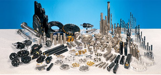
What good is a perfectly tuned spindle if the cutting tool wobbles in its holder? Tooling for CNC machines represents the critical connection point between your machine's capabilities and actual material removal. The cnc tool interface directly affects surface finish quality, dimensional accuracy, and tool life. Understanding tool holders, chucks, and tool management systems empowers you to maximize machining performance while minimizing costly errors.
Tool Holders and Chuck Systems
When you define chucks and tool holders, you're describing the mechanical devices that grip cutting tools and connect them to the spindle. This connection must be rigid, concentric, and repeatable. Any runout or looseness at this interface transfers directly to your workpiece as dimensional errors or poor surface finish.
According to CNCCookbook, different tool holder types excel in different applications. The choice involves balancing precision, versatility, ease of use, and cost against your specific machining requirements. Here's what you need to know about common chuck types and their applications:
- ER Collet Chucks: The workhorses of general machining, offering good precision and excellent versatility. A single chuck accommodates multiple shank sizes through interchangeable collets. Proper torque is critical—ER32 collets require approximately 100 ft/lbs for optimal performance, far more than many machinists realize.
- Shrink-Fit Holders: Deliver exceptional precision and rigidity through thermal interference fit. Heat expands the holder bore, the tool shank inserts, and cooling creates an extremely rigid connection. Best for high-speed finishing and demanding accuracy requirements, though they require special heating equipment.
- Hydraulic Chucks: Use oil pressure to create uniform clamping force around the tool shank. They provide excellent runout characteristics and vibration damping, making them ideal for finishing operations and long-reach applications.
- Milling Chucks (Side-Lock): Feature set screws that lock against a Weldon flat on the tool shank. While less precise than other options, they provide extremely secure clamping that prevents tool pullout during aggressive roughing operations.
- Power Chucks (Lathe Applications): Hydraulically or pneumatically actuated chucks for workholding on turning centers. Available in two-jaw, three-jaw, and four-jaw configurations for different workpiece geometries.
The precision difference between holder types is substantial. Set screw holders typically exhibit 0.0005" to 0.001" runout, while quality shrink-fit holders achieve 0.0001" or better. For high-speed machining where tool balance matters, this difference directly impacts achievable surface finish and tool life.
Automatic Tool Changers and Tool Setting
Imagine having to manually change tools between every operation on a complex part. Automatic tool changers (ATCs) eliminate this bottleneck, enabling unattended machining of multi-operation parts. These mechanisms store multiple tools in a magazine or carousel and swap them into the spindle on command, typically completing changes in seconds.
ATC designs vary based on machine type and tool capacity:
- Arm-type changers: A mechanical arm retrieves tools from a stationary magazine and exchanges them with the spindle. Common on vertical machining centers.
- Carousel/turret systems: Tools mount directly in a rotating carousel that indexes to position the required tool for spindle pickup.
- Chain-type magazines: Store large numbers of tools (60+) in a chain loop, offering high capacity for complex parts requiring many tools.
However, simply loading a tool isn't enough for precision machining. The machine must know the exact length and diameter of each tool to position cuts accurately. This is where tool setting systems become essential.
A renishaw tool setter or similar device enables automatic tool measurement directly on the machine. These systems use touch probes or laser beams to precisely measure tool length and diameter, automatically updating the controller's tool offset tables. According to Renishaw, their tool measurement systems help manufacturers reduce scrap rates, eliminate machine down-time, and improve component quality through automated tool management.
The renishaw probe technology extends beyond tool setting to include workpiece probing for automated part setup and in-process inspection. By probing the workpiece before machining, operators can automatically establish work coordinates without manual measurement. In-cycle probing verifies critical dimensions during the machining process, enabling real-time offset adjustments that ensure parts meet specifications.
For Haas machines specifically, the haas locating puck provides a standardized reference point for probe calibration and tool setting. This ground steel puck mounts in the machine table and serves as a known reference surface, ensuring consistent and accurate probe calibration across tool changes and machine startups.
The benefits of automated probing and tool measurement are substantial:
- Reduced setup time: Automated probing eliminates manual measurement steps, getting parts into production faster.
- Improved accuracy: Precise tool measurement prevents dimensional errors caused by incorrect tool length compensation.
- Broken tool detection: Systems can verify tool presence and integrity before and after operations, preventing scrap from machining with damaged tools.
- Extended unattended operation: Reliable tool management enables longer periods of lights-out machining.
Proper tool holding and management form a system where each element supports the others. The best tool setter cannot compensate for a worn collet that doesn't grip consistently. Similarly, a precision shrink-fit holder delivers maximum benefit only when paired with accurate tool length measurement. Investing in quality tooling systems pays dividends through improved part quality, reduced scrap, and increased machine utilization.
With tools properly held and measured, the next consideration is keeping everything running smoothly: the coolant and lubrication systems that protect both tools and machine components during operation.
Coolant and Lubrication Systems for Optimal Performance
Ever noticed how a CNC machine sounds different when coolant floods the cutting zone versus running dry? That audible difference reflects something far more significant happening at the tool-workpiece interface. Coolant and lubrication systems directly influence tool life, surface finish quality, and even the dimensional accuracy of your finished parts. According to research cited by Frigate, fluid-related inefficiencies can contribute up to 20% of total machining costs, while properly engineered coolant systems can increase tool life by over 200%.
These auxiliary systems often receive less attention than spindles or servo motors, yet they work continuously to protect both your cutting tools and machine components. Understanding how coolant delivery, filtration, lubrication, and chip management work together helps you maintain peak performance and avoid costly failures.
Coolant Delivery and Filtration Systems
What happens when coolant reaches the cutting zone? It performs multiple critical functions simultaneously. The fluid absorbs heat generated by the cutting process, preventing thermal damage to both tool and workpiece. It lubricates the interface between chip and tool, reducing friction and cutting forces. And it flushes chips away from the cutting area, preventing re-cutting that accelerates tool wear and damages surface finish.
Modern CNC machines employ several coolant delivery methods, each suited to different applications:
- Flood coolant: The most common method, delivering high volumes of coolant across the cutting zone through adjustable nozzles. Effective for general machining but may not penetrate deep holes or confined pockets.
- Through-spindle coolant (TSC): Pushes coolant through the spindle and out through the cutting tool itself. According to Haas, this delivers coolant precisely to the cutting edge, even in deep-hole drilling and pocket milling operations where flood coolant cannot reach.
- High-pressure coolant: Delivers coolant at pressures up to 300 psi or higher, breaking chips effectively and improving penetration in difficult-to-reach areas.
- Programmable coolant nozzles: Automatically adjust coolant direction based on tool length, eliminating manual adjustments and ensuring consistent delivery across tool changes.
- Minimum Quantity Lubrication (MQL): Applies a fine mist of lubricant rather than flood coolant, ideal for applications where water-based coolants are unsuitable or when near-dry machining is preferred.
However, coolant effectiveness degrades without proper filtration. Chips, fines, and tramp oil contaminate the fluid over time, reducing cooling efficiency and potentially damaging both the workpiece and machine components. A cnc coolant filtration system removes these contaminants, extending coolant life and maintaining consistent machining performance.
According to EdjeTech, centralized coolant filtration systems can handle up to 1500 gallons per hour or more, effectively managing coolant across multiple machines. These systems integrate various filtration technologies including paper bed filters, magnetic separators for ferrous particles, and oil skimmers that remove tramp oil floating on the coolant surface. Coalescers and oil water separators recover usable oil while maintaining coolant purity.
Lubrication and Chip Management
While coolant protects the cutting zone, separate lubrication systems protect the machine itself. Ball screws, linear guides, and way surfaces all require consistent lubrication to maintain accuracy and prevent premature wear. Most CNC machines incorporate automatic lubrication systems that deliver precise oil quantities through an oil tube network to critical wear points on programmed intervals.
Central lubrication systems typically use progressive distributors that sequentially meter oil to multiple lubrication points from a single reservoir. This ensures every bearing, guide, and ball screw receives the correct amount of lubricant regardless of operating conditions. The oil distribution system monitors for blockages or failures, triggering alarms if any lubrication point fails to receive its required dose.
Vector fans and vector fan assemblies help maintain proper operating temperatures throughout the machine by providing cooling airflow to electrical cabinets, servo amplifiers, and other heat-generating components. Proper ventilation prevents thermal issues that could affect both component life and machining accuracy.
Chip management presents another critical consideration. Accumulated chips can damage way covers, contaminate coolant, and create fire hazards with certain materials. Chip conveyors automatically transport chips out of the machine enclosure to collection bins, enabling extended unattended operation. Different conveyor types suit different chip characteristics, from small curly chips to long stringy swarf.
Way covers protect precision linear guides and ball screws from chip contamination and coolant intrusion. These accordion-style or telescoping covers seal the guideway area while accommodating axis motion. Damaged or worn way covers allow contamination to reach bearing surfaces, accelerating wear and degrading accuracy.
When auxiliary system components fail, you'll often need specialized repair parts. For hydraulic systems that power tool changers, work holding, and other actuators, hyd cylinder repair kits and hyd cyl repair kits provide the seals and components needed to restore proper operation without replacing entire assemblies.
Maintenance Indicators for Auxiliary Systems
How do you know when these behind-the-scenes systems need attention? Regular monitoring catches problems before they affect production or cause expensive damage. Watch for these warning signs:
- Coolant appearance changes: Cloudy coolant, unusual odors, or visible oil slicks indicate contamination requiring filtration system attention or coolant replacement.
- Concentration drift: Coolant concentration that falls outside manufacturer specifications affects both cooling performance and corrosion protection. Regular testing with a refractometer catches this early.
- Reduced coolant flow: Clogged filters, worn pumps, or plugged nozzles reduce delivery volume. Monitor flow indicators and inspect nozzles regularly.
- Lubrication system faults: Most machines alarm when lubrication cycles fail to complete properly. Investigate immediately, as running without lubrication rapidly damages precision components.
- Way cover damage: Torn or collapsed way covers expose guideways to contamination. Inspect regularly and replace damaged sections promptly.
- Chip conveyor jams: Unusual noises or stopped conveyors indicate jams that require clearing before chips accumulate in the machine enclosure.
- Elevated component temperatures: Hot-running motors, drives, or hydraulic systems suggest cooling problems that need investigation.
- Hydraulic system leaks: Oil puddles or dropping reservoir levels indicate seal failures requiring repair kits or component replacement.
Implementing a structured maintenance program for auxiliary systems pays dividends through extended component life, consistent machining performance, and reduced unplanned downtime. Many shops overlook these systems until failures occur, but proactive attention prevents the cascade of problems that neglected coolant and lubrication create.
With your machine's auxiliary systems maintaining proper operating conditions, the next consideration is knowing when components need replacement and how to plan maintenance effectively before problems impact production.
Maintenance Planning and Troubleshooting Common Part Failures
When does a strange noise become a warning sign? How do you distinguish between normal wear and imminent failure? Understanding component lifespan expectations and recognizing early warning signs separates proactive maintenance from expensive emergency repairs. According to AMT Machine Tools, material quality, usage frequency, and regular maintenance significantly impact CNC lathe longevity, and the same principles apply across all CNC machine types.
The challenge many shops face isn't knowing that maintenance matters, but rather knowing when to act. As noted by ToolsToday, most CNC issues stem from a few common causes: mechanical wear, programming errors, or neglected maintenance. Learning to recognize the warning signs early means the difference between a planned repair cnc operation and an emergency that halts production for days.
Recognizing Component Wear and Failure Signs
What does your machine tell you before a component fails? Every CNC machine communicates through sounds, vibrations, temperatures, and machining results. Training yourself to notice subtle changes transforms you from reactive to proactive.
Spindle bearings typically provide 10,000 to 20,000 hours of service under normal operating conditions. However, improper lubrication, contamination, or running at excessive speeds dramatically shortens this lifespan. You'll notice bearing degradation through increasing vibration, unusual noise patterns during rotation, and gradually worsening surface finish on machined parts. Temperature monitoring provides another early indicator, as worn bearings generate more heat than healthy ones.
Ball screws and linear guides follow similar patterns. Under proper lubrication and within rated loads, these components often last 15,000+ hours. Backlash that increases over time, positioning errors that appear and grow, and visible wear marks on guide rails all signal approaching end-of-life. Clean chips and dust daily and check lubrication lines regularly, as backlash and overheating often stem from neglected maintenance.
Servo motors and drives rarely fail without warning. Watch for following errors that trigger alarms, motors running hotter than normal, or unusual sounds during acceleration and deceleration. Encoder problems, shorted wires, or controller issues can be dangerous if handled improperly, so a licensed technician should handle diagnostics for electrical components.
Control system components typically offer the longest service life, often exceeding 15-20 years with proper care. However, power supply issues, failing capacitors, and connector degradation eventually occur. Intermittent errors, unexplained resets, or display anomalies warrant investigation before complete failure strands you mid-production.
Maintenance Planning for Critical Parts
How do you decide between repair and replacement? Several factors guide this decision. First, consider the component's remaining useful life versus repair cost. Rebuilding a spindle makes sense when bearings account for most of the wear, but extensive shaft damage might justify replacement. Second, evaluate downtime impact. Sometimes a quick replacement gets you running faster than waiting for repair cnc services, even if the replacement costs more.
When searching for cnc repair near me or evaluating cnc machine repair service options, consider the technician's experience with your specific machine brand and model. Bed leveling, ball screw replacement, and servo tuning are best left to experienced CNC service pros with access to proper diagnostic equipment. If you're running into recurring crashes or inconsistent tolerances, a technician with access to OEM diagnostic software can spot faults not visible through manual inspection.
For hydraulic systems, keeping hydraulic cylinder repair parts on hand minimizes downtime when seals fail. Common wear items like seals, O-rings, and wipers are inexpensive insurance against extended production losses.
The following table organizes common symptoms, their probable component causes, and recommended actions to help you troubleshoot effectively:
| Symptom | Probable Component Failure | Recommended Action |
|---|---|---|
| Increasing spindle vibration or noise | Spindle bearings worn or contaminated | Monitor temperature; schedule bearing replacement before catastrophic failure |
| Growing positioning errors on one axis | Ball screw wear, loose coupling, or encoder degradation | Check backlash measurement; inspect coupling; verify encoder signals |
| Inconsistent surface finish | Spindle runout, tool holder wear, or vibration issues | Measure spindle runout; inspect tool holders; check machine leveling |
| Axis moves rough or binds | Linear guide contamination, inadequate lubrication, or rail damage | Clean and inspect guideways; verify lubrication system operation |
| Servo alarms or following errors | Servo amplifier, motor, encoder, or wiring issues | Check connections; review alarm codes; contact cnc machine repair services |
| Intermittent control system errors | Power supply degradation, failing capacitors, or connector issues | Inspect connections; check power supply voltages; plan control upgrade |
| Hydraulic system leaks or slow response | Seal wear, pump degradation, or valve issues | Replace seals using repair kits; check pump pressure; inspect valves |
| Coolant delivery reduced or inconsistent | Clogged filters, worn pump, or plugged nozzles | Replace filters; inspect pump; clean or replace nozzles |
Developing a structured maintenance schedule prevents many failures before they occur. Daily tasks should include chip removal, coolant level checks, and visual inspection of way covers. Weekly activities might include lubrication system verification and coolant concentration testing. Monthly checks should cover backlash measurement on critical axes and spindle runout verification. Annual maintenance typically includes comprehensive alignment checks, servo tuning verification, and electrical connection inspection.
Documentation proves invaluable for maintenance planning. Track operating hours, record any anomalies noticed during operation, and log all maintenance activities. Over time, this data reveals patterns that help predict when components will need attention. A spindle that consistently shows bearing degradation at 12,000 hours on your specific machine tells you exactly when to schedule the next replacement.
Bottom line: Most CNC issues stem from a few common causes, and knowing the warning signs allows you to act early. Don't be afraid to bring in expert help when needed. A well-tuned machine is a productive machine, and investing in proper cnc machine repair service when required protects your equipment investment for years to come.
With maintenance planning established, the final consideration is knowing where to source quality replacement parts when components do need replacing, and how to evaluate suppliers to ensure you're getting components that meet your machine's demanding requirements.
Sourcing Quality CNC Parts and Evaluating Suppliers
You've identified a worn ball screw or failing spindle bearing. Now what? Finding the right cnc replacement parts isn't as simple as searching online and clicking "buy." The components you select directly impact machine accuracy, reliability, and longevity. According to Titan Machinery, the choice between original and aftermarket parts "depends on context and priorities," and understanding these trade-offs helps you make decisions that balance cost, quality, and operational requirements.
Whether you're sourcing haas parts for your machining center or seeking cnc spare parts for an older machine, the evaluation process remains consistent. Quality indicators, compatibility verification, and supplier certification all factor into making the right choice for your specific situation.
OEM vs Aftermarket Part Considerations
When that critical component fails, you'll face the age-old question: original or aftermarket? Each option carries distinct advantages and limitations that affect your operation differently depending on your priorities.
OEM (Original Equipment Manufacturer) parts, sometimes called "genuine" parts, come directly from your machine's manufacturer. Haas replacement parts, for example, are engineered specifically for Haas machines and meet the original design specifications. According to Titan Machinery, genuine parts "have been developed specifically for your equipment's design, meet the intended safety and performance standards, and often come with a warranty from the manufacturer."
The benefits of OEM components are compelling:
- Guaranteed compatibility: Parts designed for your exact machine model fit correctly without modification.
- Quality assurance: Manufacturing standards match original specifications.
- Warranty protection: Many machines retain warranty coverage when using genuine parts installed by authorized technicians.
- Technical support: Access to haas service or equivalent manufacturer support when issues arise.
- Documented specifications: Complete technical data available for installation and verification.
Aftermarket parts are manufactured by third parties and designed to fit various makes and models. They typically cost less upfront because manufacturers "utilize inferior materials and less strict requirements," though this isn't universally true. Quality varies significantly between aftermarket suppliers, from excellent alternatives to inadequate substitutes.
When might aftermarket make sense? If you're maintaining older equipment no longer supported by the original manufacturer, aftermarket or remanufactured components may be your only option. For non-critical wear items like way covers or coolant nozzles, quality aftermarket suppliers can provide adequate performance at lower cost. However, for precision components like haas spare parts affecting positioning accuracy, the savings rarely justify potential quality compromises.
Consider this scenario: You need replacement ball screw bearings for a ten-year-old machining center. Haas automation parts from the manufacturer guarantee compatibility and precision, but cost significantly more than aftermarket alternatives. The decision hinges on how critical positioning accuracy is for your typical work. If you're machining aerospace components with tight tolerances, OEM is the clear choice. For less demanding applications, a reputable aftermarket supplier might suffice.
Quality Indicators When Sourcing Components
How do you distinguish quality suppliers from those selling substandard components? According to KESU Group, evaluating CNC service providers and component suppliers requires examining technical capabilities, quality control systems, and operational reliability through measurable parameters.
When evaluating potential suppliers for cnc spare parts or precision components, examine these key quality indicators:
- Industry certifications: ISO 9001:2015 indicates adherence to international quality standards. For automotive applications, IATF 16949 certification demonstrates even more rigorous quality management requirements. Certified manufacturers like Shaoyi Metal Technology maintain these standards through documented processes and regular audits.
- Tolerance capabilities: Request specific tolerance ranges the supplier can achieve. Quality suppliers provide detailed specifications rather than vague claims. Precision levels of ±0.005 mm or better indicate high-capability manufacturing.
- Inspection methodologies: Ask about CMM (Coordinate Measuring Machine) capabilities, surface finish measurement, and in-process inspection procedures. Suppliers using Statistical Process Control (SPC) demonstrate commitment to consistent quality.
- Material certifications: Reputable suppliers provide material test certificates documenting alloy composition, heat treatment, and mechanical properties. This documentation proves especially critical for safety-related components.
- Equipment capabilities: Modern, well-maintained manufacturing equipment produces more consistent results. Ask about machine age, calibration schedules, and maintenance programs.
- Track record: Request case studies, customer references, or sample parts with measurement reports. A supplier confident in their quality welcomes this scrutiny.
Compatibility verification deserves special attention when sourcing replacement components. Even "equivalent" parts may differ in subtle ways that affect fit or function. Document your existing component specifications before searching for replacements. Note not just dimensions but also material grades, surface treatments, and any special features like lubrication ports or mounting configurations.
For critical applications requiring high-tolerance replacement parts, working with certified precision manufacturers reduces risk significantly. Shaoyi Metal Technology, for example, combines IATF 16949 certification with strict Statistical Process Control to deliver components meeting demanding automotive and industrial specifications. Their precision CNC machining services demonstrate the quality infrastructure necessary for reliable replacement components.
Making the Final Sourcing Decision
Ultimately, the right sourcing decision balances multiple factors specific to your situation. Consider these questions:
- Is the machine under warranty that could be voided by non-OEM parts?
- How critical is this component to positioning accuracy and part quality?
- What's the true cost of failure, including downtime and potential scrap?
- Does the supplier provide adequate documentation and technical support?
- Can you verify the supplier's quality claims through certifications or sample evaluation?
For machines still under manufacturer support, genuine parts often make the most sense despite higher costs. The warranty protection, guaranteed compatibility, and available technical support through services like haas service provide value beyond the component itself. When genuine parts aren't available or cost-prohibitive, focus on suppliers with documented quality systems, relevant certifications, and willingness to provide verification data.
Remember that the cheapest option rarely delivers the best value when machining precision matters. A bearing that fails after 2,000 hours costs far more than one lasting 10,000 hours when you factor in replacement labor, machine downtime, and potential damage to other components. Invest in quality components from reputable suppliers, maintain proper documentation, and your CNC machines will deliver reliable performance for years to come.
Frequently Asked Questions About CNC Machine Parts
1. What are the 7 major parts of a CNC machine?
The seven major CNC machine parts include the Machine Control Unit (MCU) that processes commands, input devices for loading programs, the drive system with servo motors and ball screws, machine tools like spindles and cutting implements, the feedback system with encoders for positioning accuracy, the bed and table providing structural stability, and the cooling system managing heat and chip evacuation. Each component works interdependently to achieve precision machining results.
2. What are CNC machine parts?
CNC machine parts are the mechanical, electrical, and control components that work together to execute automated precision machining. These include structural elements like the machine bed and frame, motion control components such as ball screws and linear guides, spindle assemblies for rotating cutting tools, servo motors with encoders for axis movement, control panels for operator interaction, tooling systems including tool holders and automatic tool changers, and auxiliary systems for coolant delivery and lubrication.
3. How long do CNC machine components typically last?
Component lifespan varies significantly based on usage and maintenance. Spindle bearings typically provide 10,000 to 20,000 hours under normal conditions. Ball screws and linear guides often exceed 15,000 hours with proper lubrication. Control system components can last 15-20 years with proper care. However, improper lubrication, contamination, or exceeding rated specifications dramatically shortens these lifespans. Regular maintenance and early detection of wear signs extend component service life substantially.
4. Should I use OEM or aftermarket CNC replacement parts?
The choice depends on your priorities and application requirements. OEM parts guarantee compatibility, meet original specifications, maintain warranty coverage, and include manufacturer technical support. Aftermarket parts cost less but quality varies significantly between suppliers. For precision components affecting positioning accuracy, OEM parts from certified suppliers like those with IATF 16949 certification typically justify the investment. For non-critical wear items, reputable aftermarket suppliers may provide adequate performance at lower cost.
5. How can I tell when CNC machine parts need replacement?
Watch for warning signs including unusual spindle noise or vibration, increasing positioning errors on specific axes, degraded surface finish on machined parts, axes moving roughly or binding, servo alarms or following errors, and intermittent control system errors. Temperature increases in spindles or motors, visible contamination or leaks, and growing backlash measurements also indicate developing problems. Documenting operating hours and tracking anomalies helps predict when components will need attention.