 Small batches, high standards. Our rapid prototyping service makes validation faster and easier —

Press Tool And Die Secrets: From Raw Concept To Production Floor
What Press Tools and Dies Actually Do in Manufacturing
Ever wondered how your car door panels, smartphone components, or kitchen appliances get their precise shapes? The answer lies in a fundamental manufacturing process that shapes our modern world: press tool and die operations. Whether you're an engineer evaluating tooling options, a buyer sourcing manufacturing partners, or simply curious about metalworking fundamentals, understanding these essential components will transform how you approach production decisions.
A press tool is a specialized assembly embedded in a press machine, designed to shape, cut, or form metal sheets using applied force. The die is the specific component within this assembly that determines the final shape and dimensions of the workpiece.
The Essential Role of Press Tools in Modern Manufacturing
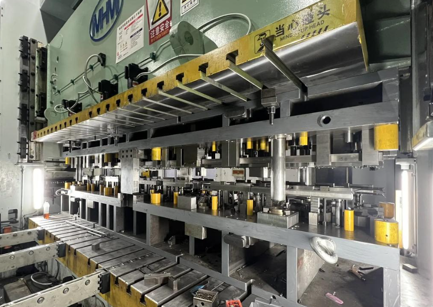
Think of a press tool as the complete system that makes metal forming possible. It's an assembly consisting of multiple components—including the die tool itself, punches, holders, and various accessories—all working together to transform flat metal sheets into precisely shaped parts. When mounted in a press machine, this assembly applies tremendous force to reshape metal according to exact specifications.
The beauty of this die tooling approach lies in two critical advantages. First, it enables mass production at remarkable speeds—you can produce thousands of identical components efficiently. Second, it delivers exceptional accuracy. Whether you manufacture one part or ten thousand, each piece maintains the same exact dimensions and shape. This consistency is why industries from automotive to aerospace rely heavily on press and die operations.
Understanding Dies as Precision Shaping Components
So, what are dies exactly? Imagine them as specialized molds or templates that define your final product's geometry. A metal die is precision-engineered with specific contours, edges, and surfaces that correspond to your desired part shape. When the press applies force, the metal workpiece conforms to these carefully designed features.
Dies come in two fundamental categories based on their function:
- Cutting dies: These feature sharp edges designed to shear, punch, blank, or trim sheet metal
- Forming dies: These shape and bend the workpiece without removing material
Each die for press applications requires meticulous engineering. The design must account for material properties, desired tolerances, and production volume requirements. A well-designed die ensures that every single part emerging from the press meets your quality standards.
How Press Tools and Dies Work Together
Here's a helpful analogy: picture your teeth. Your upper teeth function like the punch (the tool), while your lower teeth act like the die. Together, they cut food or create impressions—much like how a press tool assembly shapes metal components.
In operation, the process flows seamlessly. A metal sheet or strip feeds into the press machine. The upper portion of the assembly—typically containing the punch—descends with controlled force. The metal compresses against the die below, and depending on the tooling configuration, gets cut, formed, bent, or shaped into the final component. Stripper plates prevent the workpiece from sticking, guide pins ensure perfect alignment, and the cycle repeats with precision.
Understanding this relationship matters because every decision you make about tooling—from material selection to die type—directly impacts your manufacturing outcomes. Production costs, part quality, lead times, and scalability all connect back to how well your press and die systems are designed and maintained.
For engineers and manufacturing professionals, mastering these fundamentals isn't just academic knowledge. It's the foundation for making informed decisions about tooling investments, supplier partnerships, and production strategies that will shape your manufacturing success.
Major Die Types and When to Use Each One
Now that you understand the fundamentals of press tools and dies, let's explore the different types available and when each makes sense for your project. Choosing the right stamping die isn't just a technical decision—it directly affects your production costs, lead times, and part quality. Think of it like selecting the right vehicle for a journey: a sports car, delivery truck, and family sedan all get you from point A to point B, but each excels in different situations.
Before diving into specific die types, let's clarify three essential operations you'll encounter repeatedly:
- Blanking: Cutting a flat shape from sheet metal where the cut-out piece becomes your finished part. A blanking die essentially punches out the workpiece you need.
- Piercing: Creating holes or openings in the workpiece where the cut-out material becomes scrap. Think of it as the opposite of blanking—you're keeping the sheet with holes, not the pieces removed.
- Forming: Bending, drawing, or shaping the metal without removing material. Forming dies reshape rather than cut.
Progressive Dies for High-Volume Sequential Operations
Imagine an assembly line where each station performs a specific task, and your workpiece automatically advances through all of them. That's exactly how progressive stamping dies operate. A metal coil feeds continuously through the die, and with each press stroke, the strip advances to the next station where another operation occurs—perhaps blanking at station one, piercing at station two, and forming at station three.
The engineering genius behind punch press dies of this type lies in their efficiency. Because all operations happen in sequence within a single tool, you eliminate part handling between steps. This translates to remarkable production speeds—often hundreds or thousands of parts per hour.
Progressive dies shine when you need:
- High-volume production runs (typically 10,000+ parts)
- Small to medium-sized parts that stay attached to the carrier strip
- Multiple operations combined efficiently
- Consistent, repeatable quality across massive quantities
The tradeoff? Initial tooling costs run higher due to the complexity of designing multiple stations. However, for large production volumes, the per-part cost drops dramatically, making these stamping dies extremely cost-effective over time.
Compound Dies for Single-Stroke Multi-Feature Parts
What if you need exceptional precision on a relatively simple part? Compound dies perform multiple cutting operations simultaneously in a single press stroke at one station. Unlike progressive dies that sequence operations across multiple stations, compound dies accomplish everything at once.
A typical compound blanking die might cut the outer profile while simultaneously piercing interior holes—all in one stroke. This approach delivers several advantages:
- Superior flatness and dimensional accuracy
- Excellent concentricity between features (holes align perfectly with outer edges)
- Efficient material usage with minimal scrap
- Lower tooling costs compared to progressive dies
These press cutting dies work best for flat parts without complex three-dimensional forming requirements. If your component needs bending or deep drawing, you'll likely need a different approach. However, for precision washers, gaskets, electronic components, and similar flat parts, compound dies deliver outstanding results.
Combination Dies: The Hybrid Approach
Sometimes you need the best of both worlds. Combination dies merge cutting and forming operations into a single tool, performing both types of work in one press stroke. Picture a die stamp that blanks your part shape while simultaneously bending flanges or creating embossed features.
This hybrid approach offers flexibility for parts requiring both material removal and shape formation. The key distinction from compound dies is the inclusion of forming operations—not just multiple cutting operations. Combination dies fill the gap between purely cutting-focused compound dies and the sequential nature of progressive dies.
Transfer Dies for Complex Multi-Station Work
For larger, more intricate parts that cannot remain attached to a carrier strip, transfer die stamping provides the solution. In this process, individual parts are mechanically or robotically transferred from one stamping station to the next. Each station contributes specific operations—punching, bending, drawing, trimming—building the final product through sequential processing.
According to manufacturing experts, transfer die stamping offers flexibility that other methods cannot match. You can reorient parts between stations, accommodate larger workpieces, and incorporate operations that would be impossible with the part attached to a strip. This makes transfer stamping dies ideal for automotive body panels, appliance housings, and other substantial components.
The tradeoffs include higher operational costs due to complex setup requirements and the need for skilled labor. Setup times run longer, especially for intricate parts. However, transfer dies accommodate both short and long production runs with remarkable versatility.
Choosing the Right Forming Dies for Your Application
How do you decide which die type fits your project? Consider these critical factors:
| Die Type | Operation Complexity | Production Volume | Part Complexity | Typical Applications |
|---|---|---|---|---|
| Progressive | Multiple sequential stations | High volume (10,000+) | Small to medium parts, moderate complexity | Electrical contacts, brackets, automotive clips |
| Compound | Single station, simultaneous cuts | Low to medium volume | Flat parts requiring precision | Washers, gaskets, laminations |
| Combination | Single station, cutting + forming | Low to medium volume | Parts needing cut features and formed shapes | Hinges, simple brackets with bends |
| Transfer | Multiple stations, parts transferred individually | Flexible (short to long runs) | Large, complex 3D shapes | Automotive panels, appliance housings, cookware |
The engineering rationale behind your choice should balance initial tooling investment against per-part production costs. Progressive dies demand higher upfront investment but deliver lower per-part costs at scale. Compound and combination dies offer economical tooling for simpler parts or lower volumes. Transfer dies provide the flexibility to handle complex geometries that other methods simply cannot achieve.
Understanding these distinctions empowers you to have informed conversations with tooling suppliers and make decisions that align with both your technical requirements and budget constraints. With the right stamping die selection, you'll optimize quality, efficiency, and cost-effectiveness throughout your production lifecycle.
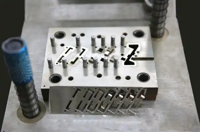
Critical Components Inside Every Die Set
You've learned about die types and when to use them—but what actually goes on inside these precision tools? Understanding the individual components within a die set isn't just academic knowledge. It's the key to recognizing quality, troubleshooting production issues, and making informed decisions when evaluating tooling suppliers. Think of it this way: knowing how a car engine works helps you understand why some vehicles outperform others. The same principle applies to die assembly components.
A complete set of die consists of structural elements, working components, and auxiliary systems that must function together with remarkable precision. According to industry experts at U-Need, a small error of just a few micrometers in one component can trigger a chain reaction of failures—wrong part dimensions, premature tool wear, costly unscheduled downtime, and elevated scrap rates. Let's examine each critical element.
Die Shoes and Plates as the Foundation
Every reliable die set begins with a solid foundation. Die shoes serve as the large, heavy base plates that form the top and bottom halves of the entire assembly. Picture them as the skeleton that holds everything else in precise alignment.
- Lower die shoe: Mounts directly to the press bed or bolster plate, providing a stable base for all lower die components
- Upper die shoe: Attaches to the press slide or ram, carrying the upper die components that descend during each press stroke
- Die plates: Also called die shoes or press die set foundations, these plates provide mounting surfaces where punches, buttons, springs, and other components are secured
Material selection matters significantly here. Most die shoes are manufactured from steel for durability and rigidity, though aluminum offers a lightweight alternative when combined with strengthening alloys. The choice depends on your specific application requirements, press tonnage, and production volume expectations.
Behind the punches and die buttons, you'll find backing plates—hardened plates that distribute force and prevent localized stress damage. These often-overlooked components protect your die shoe investment by absorbing impact loads that would otherwise deform softer base materials over millions of press cycles.
Punch and Stripper Mechanisms Explained
Now we reach the working components—the parts that directly contact and transform your metal workpiece. These elements experience the greatest stresses, friction, and wear. Their design, material composition, and manufacturing precision determine whether your finished parts meet specifications.
- Punches: The male components that perform piercing, blanking, or forming operations. Available in various nose shapes—round, oblong, square, rectangular, hexagonal, or custom profiles—punches press into the metal sheet to create your desired features
- Die buttons: The female counterparts to punches in cutting operations. These precision-ground bushings feature holes matching the punch profile with specific clearance allowances, typically 5-10% of the material thickness
- Die retainers: Placed on die plates to hold cutting and forming components firmly in position. Quality retainers like those manufactured from through-hardened alloy steel enable precise punch positioning and prevent stacking tolerance errors
The clearance between punch and die button—called the "die break"—is critical. Too tight, and you'll experience excessive tool wear. Too loose, and your cut edges will show burrs and poor quality. This tolerance relationship directly determines whether your parts meet specifications or end up as scrap.
Once material is pierced or blanked, metal elasticity causes the workpiece to grip the punch tightly. Here's where stripper plates become essential:
- Stripper plates: Remove the workpiece material from the punch as it retracts, preventing jamming and ensuring smooth cycling
- Die springs: Helical, high-force compression springs that provide the stripping force needed to hold metal sheets in place during forming and release parts after operations complete
Die springs come in mechanical (wire coil) and nitrogen gas varieties. Mechanical springs offer simplicity and reliability, while nitrogen gas springs deliver consistent force throughout their stroke—particularly valuable for deep drawing operations where force consistency matters.
Guide Systems for Alignment Accuracy
Imagine trying to cut paper with scissors where the blades don't align properly—you'd get torn edges and frustration. The same principle applies to die sets, except the consequences involve damaged tooling and rejected parts. Guide systems ensure the upper and lower die halves meet with perfect precision every single stroke.
- Guide pins: Hardened, precision-ground pins mounted on one die shoe that maintain alignment during the press stroke. Manufactured to tolerances within .0001" (one ten-thousandth of an inch) to ensure exact positioning
- Guide bushings: Precision sleeves on the opposing die shoe that receive the guide pins. The fit between pin and bushing determines alignment accuracy
- Pilots: Smaller pins that locate and position the workpiece material precisely before each operation, particularly critical in progressive dies where strip advancement must be exact
Two main guide pin types serve different applications. Friction pins (straight pins slightly smaller than their bushing bore) provide accurate guidance but require more effort to separate die halves. Ball-bearing pins glide on sequences of ball bearings within aluminum cages, offering easier separation and smoother operation—making them the industry standard for most applications.
Why Component Quality Determines Part Quality
Here's the connection that transforms good manufacturing into great manufacturing: every tolerance stack-up in your die components directly affects your final part dimensions. A die shoe that's slightly out of flat, guide pins with minor runout, or punches ground just slightly off-center—these small imperfections compound across your die assembly.
Consider the precision requirements for different applications:
- General commercial parts: Tolerances of ±0.005" to ±0.010" are typically acceptable
- Precision components: Tolerances tighten to ±0.001" to ±0.003"
- Critical aerospace or medical parts: Tolerances may reach ±0.0005" or tighter
Achieving these tolerances requires die sets manufactured with even tighter internal specifications. If your finished part needs ±0.002" accuracy, your die components must be manufactured to significantly better tolerances to account for assembly stack-ups, thermal expansion, and wear over time.
This is precisely why experienced engineers evaluate potential die suppliers based on their manufacturing capabilities, metrology equipment, and quality control processes. The cheapest die set often becomes the most expensive when you factor in scrap rates, rework, and production delays caused by inadequate precision.
With a clear understanding of what's inside your tooling, you're now equipped to evaluate die designs, discuss specifications with suppliers, and recognize quality differences that directly impact your manufacturing success.
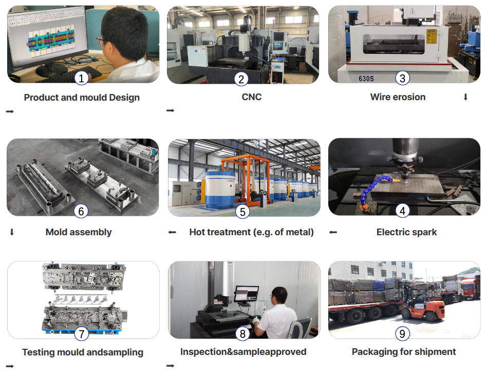
The Press Tool Design Process from Concept to Production
You now understand die types and their internal components—but how does a manufacturing die actually come to life? The journey from initial concept to production-ready tooling follows a systematic engineering process that separates successful projects from costly failures. As one industry veteran notes, spending extra time in early design stages can save weeks of tool modifications later. Let's walk through the complete die manufacturing workflow that transforms your part requirements into precision tooling.
- Part Analysis and Feasibility Assessment
- Material Selection and Die Type Determination
- CAD Modeling and Design Development
- Simulation and Virtual Validation
- Steel Selection and Die Machining
- Prototype Testing and Final Validation
Part Analysis and Feasibility Assessment
Every successful tool and die manufacturing project begins with a critical question: can this part actually be produced as designed? This isn't about doubt—it's about engineering rigor. A design might look perfect on screen but prove physically impossible to stamp efficiently.
During this phase, experienced engineers examine your part design through the lens of manufacturability. They're looking for potential issues that could cause problems during production:
- Draft angles: Parts with perfectly vertical walls won't release cleanly from the die. Adding slight angles ensures proper ejection after each press stroke
- Wall thickness uniformity: Inconsistent material thickness can cause warping, stress concentrations, and dimensional instability
- Parting line location: Where the upper and lower die halves meet affects visible seams, material flow, and overall part quality
- Feature complexity: Sharp internal corners, deep draws, and tight tolerances require specific tooling approaches
This Design for Manufacturability (DFM) review is collaborative. Your engineering team works alongside the die maker to optimize the part design for the stamping process. The goal isn't to change your functional requirements—it's to ensure those requirements can be achieved reliably at production volumes. Changes made during this stage cost almost nothing compared to modifications after tooling is built.
CAD Modeling and Simulation Integration
Once feasibility is confirmed, the design moves into digital development. Modern die making relies heavily on sophisticated CAD/CAM software that streamlines everything from blank design to strip layout and forming analysis. According to Cimatron, integrated design environments enable toolmakers to save time and improve quality even when producing the most complex dies.
The CAD modeling phase encompasses several critical decisions:
- Blank design: Determining the optimal flat pattern that will form into your finished part with minimal material waste
- Strip layout: For progressive dies, engineers determine station count, pitch distance, strip width, and nesting parameters to maximize efficiency
- Forming sequence: Establishing the order and method of each forming operation to achieve desired geometry without overstressing the material
- Punch and matrix design: Creating the specific cutting and forming tools using advanced surface and solid modeling capabilities
Why does simulation matter so much? Think of it as a crystal ball for your die machining project. Mold flow and forming simulations predict exactly how metal will behave during stamping—where it will stretch, compress, thin, or potentially crack. Engineers can test multiple design approaches digitally before cutting any steel.
Real-time simulation during the design phase catches problems early. If analysis reveals risk of material thinning in a critical area, designers can modify draw depths, add draw beads, or adjust blank holder pressure—all within the software. Finding and fixing such issues digitally takes hours. Discovering them after the tool is built takes weeks of welding, re-machining, and retrials.
Collision detection and motion analysis validate that all moving components operate without interference. Designers visualize vertical axis movements, analyze kinematics, and verify clearances throughout the press stroke cycle. This virtual validation eliminates costly surprises during physical tryout.
Prototype Testing and Design Validation
Digital validation provides confidence, but physical reality delivers proof. The transition from CAD model to physical tooling involves precision manufacturing processes that transform your validated design into hardened steel components.
Steel selection represents a critical decision point. For stamping dies, H13 tool steel is the industry standard because it offers excellent resistance to the thermal cycling and mechanical stresses of production stamping. Machining dies from inferior materials might save money initially, but premature wear and failure quickly erases any savings.
The machining process combines multiple technologies:
- CNC milling: Computer-controlled cutting tools carve the main die shapes from steel blocks with high precision
- EDM (Electrical Discharge Machining): For fine details, sharp corners, and complex geometries, controlled electrical sparks erode steel to exact specifications
- Grinding and polishing: Final surface finishing achieves the smooth, precise surfaces required for quality stamped parts
- Heat treatment: Vacuum furnace processing hardens the steel to 44-48 HRC, providing the durability needed for millions of production cycles
After assembly, the moment of truth arrives: the T1 trial. This first physical test runs actual production material through the completed die. Engineers inspect initial parts for visual defects, then measure critical dimensions on coordinate measuring machines (CMM). The dimensional report reveals whether every specification matches the engineering drawings.
Successful validation means your die for manufacturing is ready for production. If adjustments are needed, they're made precisely based on measured data—not guesswork. This systematic approach ensures that when tooling reaches your production floor, it delivers parts meeting your exact specifications from the first stroke forward.
Understanding this workflow helps you evaluate potential tooling partners, set realistic project timelines, and recognize the engineering decisions that determine whether your manufacturing die investment delivers long-term value or ongoing headaches.
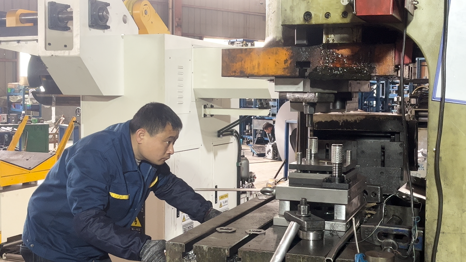
Matching Press Machines to the Right Tooling
You've designed the perfect die—but will it perform optimally in your press machine? This critical question often gets overlooked, yet the relationship between your metal press and compatible tooling directly determines production success. Think of it like pairing an engine with a transmission: even the best components underperform when mismatched. Understanding how different press machine for metal applications work alongside specific die configurations will transform your equipment decisions from educated guesses into strategic investments.
According to manufacturing experts at Eigen Engineering, selecting the correct metal press machine is more than a technical choice—it's a strategic decision affecting production speed, part quality, maintenance requirements, and long-term costs. Let's explore how each press type pairs with your tooling.
Hydraulic Press Tooling Requirements
When working with heavier or high-tensile materials, hydraulic press tooling becomes the preferred solution. These machines generate force through fluid compression, delivering consistent pressure throughout the entire stroke. Imagine squeezing a tube of toothpaste—the pressure remains steady from start to finish. That's how a hydraulic press die set operates.
What makes hydraulic press die configurations unique? Several factors distinguish their tooling requirements:
- Full tonnage availability: Unlike mechanical presses, hydraulic systems deliver maximum force at any point in the stroke—critical for deep drawing operations where consistent pressure prevents material tearing
- Adjustable speed control: Tooling can be designed for variable approach speeds, slower forming speeds, and rapid return strokes
- Dwell capability: Dies can be designed to hold at bottom dead center under full pressure—essential for certain forming and coining operations
- Overload protection: Built-in pressure relief prevents die damage from unexpected resistance
The tradeoff? Hydraulic systems operate slower than mechanical alternatives. Your steel press tooling must account for longer cycle times in production planning. However, for complex stamped metal parts requiring controlled force application, this consistency proves invaluable.
Mechanical Press Die Compatibility
Need speed? Mechanical presses employ a flywheel to generate force, making them the workhorses of high-volume metal forming press operations. These machines excel at repetitive stamping where cycle time directly impacts profitability.
Designing dies for mechanical presses requires understanding their unique characteristics:
- Fixed stroke profile: Force peaks near bottom dead center, so die designs must account for this energy curve
- High-speed capability: Progressive and compound dies thrive in mechanical presses running hundreds of strokes per minute
- Consistent timing: The predictable stroke pattern enables precise automation integration
- Snap-through energy: The flywheel's stored energy provides the "punch" needed for blanking and piercing operations
However, mechanical presses offer less control at the bottom of the stroke compared to hydraulic alternatives. For operations requiring precise force modulation throughout forming, this limitation matters. Your die design must accommodate these physics—ensuring critical forming happens where the press delivers optimal force.
Servo Press: The Best of Both Worlds
Modern servo press technology represents the new frontier in metal press capabilities. These machines use advanced servo motors to provide programmable control over speed, position, and force throughout every stroke cycle. According to Tolomatic, servo-electric presses offer significant advantages in precision, programmability, energy efficiency, and flexibility compared to traditional hydraulic machines.
Servo press benefits for die compatibility include:
- Infinite motion profiles: Program different speeds for approach, forming, and return phases—optimizing each for your specific die requirements
- Real-time force monitoring: Ram force, speed, and position are continuously monitored and adjusted throughout each cycle
- Quick changeover: Stored programs enable rapid die changes with optimized parameters for each tool
- Energy efficiency: Motors only consume power during actual work, reducing operating costs
These capabilities make servo presses ideal for precision die and stamping applications in electronics, medical devices, and high-end automotive components where accuracy trumps raw speed.
Matching Tonnage to Die Design
How much force does your die actually need? This question determines press selection more than any other factor. Undersized presses struggle and fail; oversized presses waste capital and floor space.
Tonnage calculations must account for:
- Material type and thickness: Harder materials and thicker gauges require proportionally more force
- Cutting perimeter: Blanking and piercing force equals material shear strength multiplied by cut length and thickness
- Forming requirements: Drawing, bending, and coining operations each have specific force formulas
- Safety margin: Most engineers specify 20-30% additional capacity beyond calculated requirements
| Press Type | Compatible Die Configurations | Tonnage Considerations | Speed Capabilities | Best Applications |
|---|---|---|---|---|
| Hydraulic | Deep draw dies, compound dies, transfer dies | Full tonnage throughout stroke; ideal for heavy forming | 10-30 strokes per minute typical | Large panels, deep-drawn parts, high-tensile materials |
| Mechanical | Progressive dies, blanking dies, high-speed compound dies | Peak tonnage near bottom; size for worst-case loading | 60-1,500+ strokes per minute | High-volume production, electrical components, fasteners |
| Servo | All die types; excels with precision forming dies | Programmable force profiles; real-time adjustment | Variable; optimized per operation | Precision parts, complex forming, quick-change environments |
The relationship works both ways: press capabilities influence die design, and die requirements guide press selection. A metal forming press with insufficient tonnage will damage tooling and produce defective parts. Conversely, a die designed for slow hydraulic operation may not survive the snap-through forces of a high-speed mechanical press.
Understanding these interdependencies helps you make equipment decisions that optimize both tooling investment and production efficiency. When evaluating new press equipment or designing dies for existing machines, always consider this critical partnership between machine and tooling.
Cost Factors That Drive Press Tool Investment Decisions
You've selected your die type, understood the components, and matched your press machine—but what will this tooling actually cost? More importantly, how do you evaluate whether that investment makes financial sense? Understanding the economics behind die press investments separates informed decision-makers from those who face budget surprises months into production. Let's explore the cost factors that truly matter.
According to manufacturing experts at Die-Matic, an extensive list of factors impacts overall tooling costs: materials, die equipment, production volume, part complexity, lead time, labor costs, and waste. The challenge isn't just knowing these factors exist—it's understanding how they interact to determine your total investment.
Initial Investment vs Long-Term Value
Here's a reality check that surprises many first-time buyers: the initial purchase price of your custom die represents only a fraction of your total expenditure. Smart manufacturers focus on Total Cost of Ownership (TCO)—a calculation that examines complete costs from purchase through the end of the tool's useful life.
What drives your upfront tooling investment?
- Profile complexity: Simple, symmetrical shapes cost significantly less to manufacture than complex, asymmetrical profiles with internal voids. According to industry analysis, complexity is the primary cost driver in die manufacturing
- Size and material requirements: Larger dies require more steel, more machining time, and more robust press equipment
- Tolerance specifications: Precision dies with tight tolerances demand additional grinding, EDM work, and quality verification steps
- Number of stations or cavities: Progressive dies with multiple stations cost more than single-station compound dies
- Surface finish requirements: Parts requiring specific textures or mirror finishes need additional die polishing and treatment
The real question isn't "what's the cheapest die?" but rather "what die delivers the best value over its production life?" Investing in high-quality tool design ensures accurate, consistent production while minimizing errors and rework. More durable tools require less maintenance and reduce replacement costs over millions of press cycles.
How Production Volume Affects Tooling ROI
Imagine buying a $50,000 precision die to produce 100 parts versus 1,000,000 parts. The math changes dramatically. This is the core principle of amortization—spreading your fixed tooling cost across your entire production run.
Consider this example: a $1,500 die used to produce 100,000 parts adds only $0.015 per unit to your cost. As production volume increases, this per-unit tooling expense approaches zero, making material and labor the dominant expenses. This principle is why dies manufacturing for high-volume applications delivers exceptional returns despite higher initial investments.
When evaluating tooling ROI, consider these volume-related factors:
- Breakeven analysis: Calculate the production quantity where tooling investment pays for itself through per-part savings compared to alternative manufacturing methods
- Economies of scale: Standardizing parts across different products can increase effective volume and reduce per-unit costs
- Die life expectancy: Quality tooling rated for millions of cycles provides better long-term value than cheaper alternatives requiring earlier replacement
- Secondary operation elimination: Custom die equipment that integrates multiple features can eliminate downstream machining, welding, or assembly—dramatically improving total cost per part
The key insight? Don't compare die prices in isolation. Compare total production costs across the expected volume, including all downstream operations your die design might eliminate.
Hidden Costs in Die Manufacturing
Beyond the obvious expenses lurk cost factors that catch unprepared buyers off guard. According to ABDO Solutions, TCO involves accounting for all costs and benefits over the lifetime of a purchase—including indirect costs, opportunity costs, and hidden expenses.
Watch for these often-overlooked cost drivers:
- Design iterations: Insufficient upfront DFM (Design for Manufacturability) review leads to costly redesigns and tooling adjustments after initial trials
- Material waste: Poorly optimized strip layouts increase scrap rates throughout your entire production run
- Maintenance and sharpening: Precision dies require scheduled maintenance. Budget for periodic sharpening, component replacement, and preventive care
- Downtime costs: Unexpected tool failures halt production lines. The cost of idle equipment and labor often exceeds the repair expense
- Quality failures: Inadequate die equipment produces parts requiring rework or causing warranty claims—costs that compound over time
- Lead time premiums: Rush orders and expedited timelines carry significant price premiums. Planning ahead reduces these expenses
Working with experienced die shops provides another often-overlooked advantage: their expertise helps you avoid costly mistakes. Early prototyping in the design phase identifies potential issues before mass production, enabling manufacturers to avoid expensive redesigns and tooling modifications later in the process.
The right manufacturing partner knows how to balance value with affordability—helping you save money on metal components without compromising quality.
When budgeting for your next press tool investment, resist the temptation to focus solely on the quoted die price. Instead, build a comprehensive cost model that accounts for production volume, expected die life, maintenance requirements, and the downstream savings your tooling design enables. This framework transforms tooling decisions from price comparisons into strategic investments that deliver measurable returns.
With a clear understanding of cost factors, you're now equipped to evaluate tooling proposals intelligently—and that evaluation naturally leads to questions about maintaining your investment for maximum lifespan.
Maintaining Press Tools for Maximum Lifespan
You've invested significantly in quality tooling—but how do you protect that investment over millions of press cycles? Maintenance isn't just about fixing what's broken. It's about preventing failures before they halt production, ship defective parts, or damage expensive die tools beyond repair. According to manufacturing experts at The Phoenix Group, a poorly defined die shop management system can dramatically decrease press line productivity and increase costs far beyond the visible repair expenses.
Here's the reality: poor die maintenance causes quality defects during production, drives up sorting costs, increases the likelihood of shipping defective parts to customers, and risks expensive forced containments. Lost press time while making temporary modifications "under the ram" doubles your maintenance costs when those fixes must be permanently corrected before the next production run.
Preventive Maintenance Schedules That Extend Die Life
Strategic tooling dies maintenance shifts your approach from reactive crisis management to proactive lifecycle management. Rather than waiting for failures, you address potential issues before they disrupt production. This systematic approach treats your press dies as valuable production assets rather than disposable consumables.
A comprehensive maintenance schedule should include these essential tasks:
- After every production run: Clean all die surfaces, remove metal debris and lubricant buildup, inspect cutting edges visually for chips or damage
- Weekly or after set intervals: Check guide pin and bushing wear, verify spring tension and condition, lubricate moving components
- Monthly: Measure critical dimensions against baseline specifications, inspect steel dies for surface cracks or fatigue indicators, verify alignment systems
- Quarterly: Complete tear-down inspection of high-wear components, regrind cutting edges as needed, replace worn springs and bushings
- Annually: Full die audit including dimensional verification, hardness testing of working surfaces, and comprehensive documentation updates
Regrinding represents one of the most critical maintenance skills. It's far more than simply "sharpening"—it's a precision machining process that restores exact tool geometry. Proper technique includes selecting the correct grinding wheel for your steel type, maintaining consistent coolant flow to prevent thermal damage, and removing only the minimum material necessary to restore sharp cutting edges.
Recognizing Early Warning Signs of Die Wear
Your pressing die communicates its condition through the parts it produces. Learning to read these signals enables predictive maintenance—addressing problems before they cause production failures. According to wear analysis experts at Keneng Hardware, several distinct mechanisms cause die deterioration.
Watch for these early warning indicators:
- Increased burr height: When cut edges show progressively larger burrs, your punch-to-die clearance has increased due to wear
- Dimensional drift: Parts gradually moving out of specification indicate tool wear affecting critical dimensions
- Surface scratches on formed parts: Scoring on part surfaces reveals abrasive wear or material adhesion on die surfaces
- Inconsistent hole sizes: Variation in pierced features suggests punch wear or alignment degradation
- Material galling: Built-up metal deposits on machine dies indicate inadequate lubrication or material compatibility issues
- Increased press tonnage requirements: When the same operation requires more force, friction from worn surfaces is likely the cause
Different materials accelerate specific wear modes. Advanced high-strength steels cause rapid abrasive wear on cutting edges. Stainless steel tends toward adhesive wear and galling. Aluminum alloys, despite being softer, react with tool surfaces and build up deposits. Understanding your material's "personality" helps predict which wear modes to monitor most closely.
Troubleshooting Common Stamping Defects
When quality issues emerge, systematic troubleshooting traces symptoms back to root causes. This structured approach prevents the common mistake of addressing visible problems while ignoring underlying failures that will recur.
Common defect patterns and their typical causes include:
- Excessive burrs: Worn cutting edges, improper clearance, dull punches requiring sharpening
- Part distortion or warping: Uneven stripper pressure, worn guide systems causing misalignment, improper blank holder force
- Cracking during forming: Material overstressing, insufficient lubrication, worn draw radii on tooling dies
- Inconsistent dimensions: Guide pin wear, loose components, thermal expansion during extended runs
- Surface defects: Material buildup on die surfaces, inadequate cleaning between runs, contaminated lubricant
The 5-Why method proves invaluable for root cause analysis. When a punch fails prematurely, keep asking "why" until you reach a process or human-level cause you can actually address. Perhaps the punch failed because of chipping, which occurred because of inadequate lubrication, which happened because the lubrication system wasn't checked during setup, which resulted from incomplete setup procedures. Now you've identified a corrective action that prevents recurrence.
Connecting maintenance to production outcomes reveals the true value of systematic care. Well-maintained tooling produces consistent parts, reduces scrap rates, minimizes unplanned downtime, and extends die life—often by years. The investment in regular maintenance pays returns through every aspect of your manufacturing operation, from quality metrics to customer satisfaction.
With your maintenance program established, the next consideration becomes equally important: selecting a manufacturing partner capable of designing and building tooling that performs reliably throughout its intended lifecycle.
Choosing a Reliable Die Manufacturing Partner
You've mastered the technical fundamentals—die types, components, design processes, press matching, cost factors, and maintenance strategies. But here's the question that ultimately determines your manufacturing success: who will actually build your tooling? Selecting the right die maker isn't just about finding the lowest quote. It's about identifying a partner whose capabilities, quality systems, and engineering expertise align with your production requirements.
According to industry experts, the choice of punch and die manufacturers can either make or break a business. The right partner consistently produces highly sophisticated parts, ensuring the safety and reliability of your products while improving productivity and cost efficiency. Let's explore the evaluation criteria that separate exceptional stamping tool and die suppliers from the rest.
Certifications That Signal Manufacturing Excellence
When evaluating potential die manufacturers, certifications provide objective evidence of quality management systems and industry-specific capabilities. Think of certifications as a manufacturer's credentials—they demonstrate verified competence in meeting demanding standards.
Key certifications to look for include:
- IATF 16949: The gold standard for automotive suppliers, this certification indicates rigorous quality management systems specifically designed for the automotive supply chain. If you're producing automotive components, working with an IATF 16949-certified partner significantly reduces qualification headaches
- ISO 9001: The foundational quality management certification demonstrating systematic process control and continuous improvement commitment
- AS9100: Essential for aerospace applications, indicating compliance with the stringent requirements of aviation and defense industries
- ISO 14001: Environmental management certification showing responsible manufacturing practices
Beyond certifications, assess the technical expertise and experience of your prospective partner. Only when a supplier demonstrates technical competence in the design and construction of precision die and stamping tooling can they consistently deliver superior results. Ask pointed questions: How do they ensure production methods remain reliable and efficient? Can they foresee problems and provide tailored solutions?
For example, Shaoyi's precision stamping die solutions demonstrate what certification-backed excellence looks like in practice—their IATF 16949 certification combined with advanced CAE simulation capabilities enables defect-free results that meet demanding OEM standards.
Evaluating Prototyping and Lead Time Capabilities
In today's competitive manufacturing environment, speed matters. Your die maker's ability to move quickly from concept to physical tooling can mean the difference between capturing market opportunities and watching competitors win contracts.
When assessing lead time capabilities, consider these factors:
- Rapid prototyping capacity: Can the supplier produce prototype tooling quickly for design validation? Some stamping die manufacturers offer prototyping in as little as 5 days—a capability that dramatically accelerates your development cycles
- Simulation-driven design: Advanced CAE (Computer-Aided Engineering) simulation capabilities enable virtual validation before steel is cut, reducing trial-and-error iterations
- In-house machining equipment: Suppliers with comprehensive CNC machining, EDM, and grinding capabilities control their schedules rather than depending on subcontractors
- Scalability: Can the provider transition smoothly from low-volume prototypes to high-volume production tooling without quality degradation?
According to Ohio Valley Manufacturing, quality control measures implemented throughout the manufacturing process—from design through testing—identify and address defects before they become production problems. This proactive approach keeps projects on schedule.
Lead time commitments must be reliable, not aspirational. Supply chain disruptions in automotive manufacturing cause cascade failures across production lines. Ask potential partners about their track record: What percentage of projects deliver on the original timeline? How do they handle unexpected delays?
Quality Metrics That Matter in Die Manufacturing
Certifications and speed mean nothing if the resulting tooling fails to produce quality parts. The metrics that truly matter reveal a die maker's ability to deliver production-ready tooling that performs from day one.
Evaluate potential metal stamping dies suppliers using these quality indicators:
- First-pass approval rate: What percentage of dies produce acceptable parts on the initial trial? Industry-leading suppliers achieve rates above 90%—Shaoyi, for instance, maintains a 93% first-pass approval rate, minimizing costly rework and delays
- Dimensional capability studies: Can the supplier provide Cpk data demonstrating consistent performance within specified tolerances?
- Material expertise: Does the partner understand the specific requirements of your materials—whether high-strength steel, aluminum, or specialty alloys?
- Full-cycle support: The best partners offer comprehensive capabilities from design concept through prototyping, production ramp-up, and ongoing support
- Customer testimonials and references: What do existing customers say? A trusted provider earns loyalty through consistent performance
Tools and processes matter equally. According to industry analysis, advanced production capabilities including CNC machining, progressive die stamping, and automatic quality control systems enable the precision and consistency that demanding applications require. Evaluate whether your prospective supplier invests in current technology or relies on aging equipment.
Building a Long-Term Partnership
The best die manufacturers become strategic partners rather than transactional vendors. Customer service plays an essential role—the right providers work closely with you from start to finish, addressing concerns promptly and ensuring satisfaction throughout the relationship.
Consider these partnership qualities:
- Collaborative approach: Does the supplier engage proactively in design optimization, or simply build what you specify?
- Communication transparency: Will they flag potential issues early, or will you discover problems at delivery?
- Continuous improvement mindset: Do they invest in advancing their capabilities and passing benefits to customers?
- Warranty and support: What guarantees back the tooling investment? Quality die manufacturers stand behind their work
Your manufacturing success shouldn't be left to chance. The time invested in thoroughly evaluating die manufacturers pays dividends through every production run—in quality, efficiency, and peace of mind. Whether you're sourcing your first stamping tool and die or expanding your supplier base, these evaluation criteria will guide you toward partners capable of supporting your long-term manufacturing goals.
Frequently Asked Questions About Press Tools and Dies
1. What is the die in press tool?
A die is a specialized precision component within a press tool assembly that determines the final shape and dimensions of metal workpieces. Dies come in two main categories: cutting dies with sharp edges for shearing, punching, blanking, or trimming operations, and forming dies that bend or shape metal without removing material. The die works in conjunction with punches and other components to transform flat metal sheets into precisely shaped parts through applied force.
2. What is a die press used for?
A die press is used to shape, cut, or form metal sheets into precise components through applied force. Common applications include blanking (cutting flat shapes), piercing (creating holes), and forming (bending or drawing). Industries from automotive to aerospace rely on die press operations because they enable mass production at high speeds while maintaining exceptional accuracy across thousands of identical parts.
3. How many types of die sets are used in a press tool?
Four main die types are commonly used: progressive dies for high-volume sequential operations, compound dies for single-stroke multi-feature flat parts, combination dies that merge cutting and forming in one stroke, and transfer dies for complex multi-station work on larger components. Each type serves specific production needs based on volume requirements, part complexity, and manufacturing goals.
4. What is the difference between tool and die and stamping?
Tool and die refers to the design and manufacturing of the specialized equipment (dies, punches, and assemblies) used in metalworking. Stamping is the actual production process where these tools are used in a press machine to shape metal into desired forms. Essentially, tool and die is where production capability is created, while stamping is the process that uses these tools to manufacture parts at scale.
5. How do I choose the right die manufacturing partner?
Evaluate potential partners based on certifications (IATF 16949 for automotive), simulation capabilities, prototyping speed, and first-pass approval rates. Look for suppliers with comprehensive in-house machining, transparent communication, and proven track records. Quality partners like those with 93% first-pass approval rates and rapid prototyping capabilities can significantly reduce development timelines and ensure production-ready tooling from day one.