 Small batches, high standards. Our rapid prototyping service makes validation faster and easier —

CNC Lathing Vs Manual Turning: The Productivity Gap Nobody Mentions
Understanding CNC Lathing and Its Role in Modern Manufacturing
Ever wondered what separates a perfectly cylindrical aerospace component from a rough metal rod? The answer lies in CNC lathing—a technology that has fundamentally transformed how manufacturers produce precision parts. If you've searched "what is a CNC lathe" or tried to define lathe operations in modern contexts, you're about to discover why this process stands at the heart of industries demanding absolute accuracy.
CNC lathing is a subtractive machining process in which computer numerical control guides cutting tools to remove material from a rotating workpiece, creating precise cylindrical, conical, and helical shapes with tolerances measured in microns.
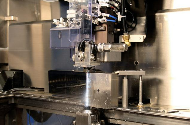
Think of it this way: while the workpiece spins at high speeds on the spindle, cutting tools move along programmed paths to shape the material exactly as designed. The "CNC" in CNC lathe stands for computer numerical control, meaning every movement follows digital instructions rather than relying on manual operator adjustments. This fundamental shift from human hands to precision programming represents nothing short of a manufacturing revolution.
The Core Mechanics Behind CNC Lathing
Understanding the lathe meaning in modern manufacturing requires grasping one essential concept: rotational machining. Unlike milling operations where the cutting tool rotates, a CNC lathe machine rotates the workpiece itself. Picture a cylindrical metal bar spinning rapidly while a stationary cutting tool approaches it, carefully removing material layer by layer.
This process enables several critical operations:
- Turning: Reducing the diameter of the workpiece to create smooth cylindrical surfaces
- Facing: Creating flat surfaces perpendicular to the rotation axis
- Grooving: Cutting channels or recesses into the material
- Threading: Producing both internal and external screw threads
- Boring: Enlarging existing holes with exceptional precision
The computer numerical control lathe interprets G-code programming—a specialized language that translates CAD designs into precise machine movements. Every cut, every path, every depth is predetermined, eliminating the variability that plagued traditional manual operations.
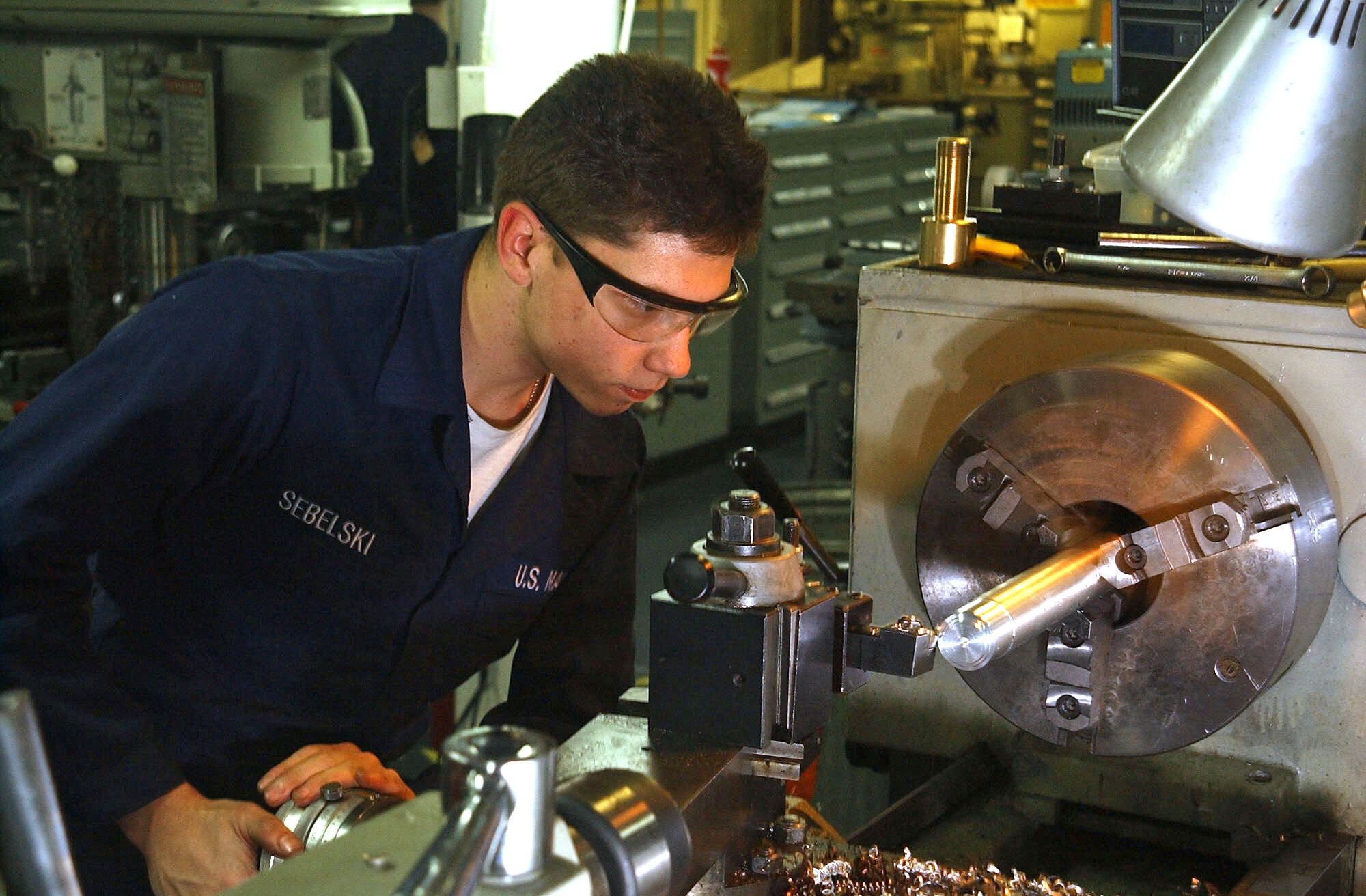
From Manual Turning to Automated Precision
Before CNC turning technology emerged, machinists relied entirely on skill, experience, and steady hands. Imagine needing to produce 500 identical shafts—each one depending on an operator's ability to replicate exact movements. The results? Inconsistent tolerances, higher scrap rates, and production bottlenecks that frustrated manufacturers across industries.
The transition to CNC lathe machining solved these fundamental problems. According to industry data, modern CNC lathes achieve tolerances as tight as ±0.005mm for demanding applications, with standard precision hovering around ±0.01mm. This level of accuracy would be virtually impossible to maintain consistently through manual operations.
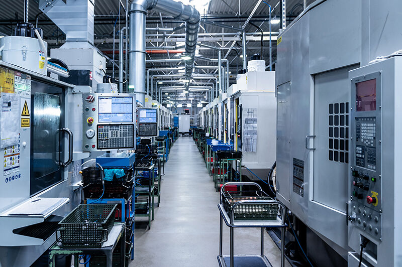
Today, CNC lathing serves as an indispensable technology across multiple sectors:
- Automotive: Engine components, transmission shafts, and precision gears
- Aerospace: Turbine elements, fasteners, and flight-critical components
- Medical devices: Surgical tools, implant components, and diagnostic equipment
- Electronics: Heat sinks, connectors, and semiconductor housings
Whether you're producing a single prototype or scaling to mass production, CNC lathe technology provides the consistency, speed, and precision that modern manufacturing demands. The productivity gap between manual turning and automated CNC processes isn't just significant—it's transformative. And understanding this gap starts with knowing exactly how these remarkable machines operate.

Essential Components of a CNC Lathe Machine
You've seen what CNC lathing accomplishes—but what actually makes these machines tick? Understanding the parts of a CNC lathe transforms you from a casual observer into someone who can diagnose problems, optimize processes, and make informed purchasing decisions. Let's break down each critical component and explore how they work together to create precision parts.
Critical Components That Power Every CNC Lathe
Every CNC lathe machine functions as an integrated system where each component plays a specific role. Think of it like an orchestra—the headstock provides power, the bed maintains stability, and the controller coordinates everything. When one element underperforms, the entire system suffers.
| Component | Primary Function | Impact on Machining | Importance Level |
|---|---|---|---|
| Headstock | Houses the main spindle and drive motor; provides rotational power | Determines maximum workpiece diameter (swing) and available cutting power | Critical |
| Bed | Serves as the machine's foundation; supports all other components | Affects vibration damping and long-term accuracy | Critical |
| Chuck | Clamps and centers the workpiece during rotation | Directly impacts part concentricity and safety | Critical |
| Tailstock | Supports the free end of long workpieces to prevent deflection | Essential for accuracy on slender parts | High (job-specific) |
| Tool Turret | Holds and indexes multiple cutting tools automatically | Enables multi-operation machining without manual intervention | Critical |
| CNC Controller | Interprets G-code and coordinates all machine movements | Determines precision, speed, and available features | Critical |
| Guideways | Precision tracks that enable smooth linear movement | Fundamental to positioning accuracy along lathe axes | Critical |
The headstock sits on the left side of a center lathe and acts as the machine's powerhouse. According to Xometry's technical resources, the headstock's dimensions dictate the lathe's "swing"—the maximum diameter of any workpiece that can fit in the machine. The main bearings within the headstock carry significant loads from cutting forces, making them a critical service item that requires monitoring, especially in heavily used machines.
The machine bed forms the foundation upon which everything rests. High-quality beds are typically manufactured from cast iron, ductile iron, or specialized materials like Granitan (an artificial casting stone). Why does material choice matter? A simple test reveals the answer: strike the bed with a hammer. A dull "thud" indicates high hysteresis—meaning the material absorbs vibrations effectively. A higher-pitched "ding" suggests poor damping properties that can compromise precision.
Many modern machines utilize a slant bed design rather than a flat configuration. This angled approach offers two advantages: gravity helps chips and coolant fall away from the cutting zone, and operators gain better access to the workpiece during setup.
The chuck physically grips the workpiece and maintains its position during rotation. Several chuck types serve different applications:
- 3-jaw self-centering chucks: Ideal for round stock; jaws move together automatically
- 4-jaw independent chucks: Each jaw adjusts separately for irregular shapes or precise centering
- Collet chucks: Provide exceptional grip accuracy for smaller diameter parts
- Hydraulic chucks: Deliver consistent clamping force for production environments
The tailstock sits opposite the headstock along the same CNC lathe axis. Its quill—a movable hollow shaft—can be driven toward the workpiece to provide support through a center point. For long or slender parts, this support prevents bending and vibration under cutting forces. Modern tailstocks can be manually positioned or programmatically controlled for automated setup.
The tool turret represents the business end of CNC lathe components. With 8, 12, or even 16 tool stations, the turret rotates automatically to bring the correct cutter into position when the program calls for a tool change. This automated indexing eliminates manual tool changes and dramatically reduces cycle times.
The Control System Brain Behind Precision Cuts
Sounds complex? Here's where everything comes together. The CNC controller serves as the machine's brain, translating G-code programming into coordinated physical movements. This sophisticated system bridges the gap between digital design and physical reality.
The control interface consists of two primary elements:
- Machine panel: Allows operators to jog the lathe axes, adjust tool positions, and manually control operational characteristics
- Control panel: Enables program entry, editing, and modification with an integrated display showing the active G-code
Popular controller manufacturers include Fanuc, Siemens, and Haas—each offering different feature sets and programming environments. The controller's sophistication directly impacts what operations the machine can perform and the precision it can achieve.
When the controller sends commands, the drive system creates physical movement. Servo motors connect to high-precision ball screws that convert rotational motion into incredibly accurate linear travel. The carriage—which holds the tool turret—travels along hardened guideways that ensure perfectly straight paths. This precision in the drive system determines whether your finished parts meet tolerance requirements or end up as scrap.
The relationship between component quality and achievable tolerances is direct and measurable. A machine with worn guideways, a headstock with degraded bearings, or an outdated controller simply cannot produce the same results as well-maintained, high-quality equipment. When manufacturers claim tolerances of ±0.005mm, they're assuming every component in the system performs as designed.
Understanding these lathe cnc parts prepares you for the next critical consideration: which type of CNC lathe best matches your production requirements?
Types of CNC Lathes and Their Specialized Applications
So you understand the components—but which CNC lathe configuration actually fits your production needs? This question trips up many manufacturers because CNC lathes aren't one-size-fits-all machines. From basic 2-axis setups handling straightforward cylindrical parts to sophisticated multi-axis systems tackling aerospace geometries, selecting the right machine type can mean the difference between profitable production and costly bottlenecks.
Matching Lathe Types to Your Production Needs
The variety of CNC lathes available today reflects decades of engineering evolution aimed at solving specific manufacturing challenges. Let's examine the primary configurations and where each excels.
| Lathe Type | Axis Configuration | Ideal Applications | Complexity Level | Typical Industries |
|---|---|---|---|---|
| 2-Axis Lathe | X, Z axes | Basic turning, facing, grooving, threading | Entry-level | General manufacturing, job shops |
| Multi-Axis Lathe (4-5+ axes) | X, Z, C, Y, B axes | Complex contours, off-center features, angled drilling | Advanced | Aerospace, defense, automotive |
| Swiss-Type Lathe | Typically 5-7+ axes | Small precision parts, long slender components | Specialized | Medical devices, watchmaking, electronics |
| Horizontal Lathe | 2-5+ axes | Shafts, longer workpieces, general turning | Standard to advanced | Automotive, industrial machinery |
| Vertical Turning Center | 2-5+ axes | Large diameter, heavy, short parts | Specialized | Energy sector, heavy equipment |
| Live Tooling Lathe | 3-5+ axes with driven tools | Milling, drilling, tapping on turned parts | Advanced | Aerospace, medical, automotive |
2-axis CNC lathes represent the workhorse configuration for standard turning operations. The X-axis controls tool movement toward and away from the workpiece centerline, while the Z-axis handles movement along the workpiece length. If your production involves straightforward cylindrical parts—shafts, bushings, or simple threaded components—a 2-axis horizontal lathe delivers reliable results without unnecessary complexity or cost.
Swiss-type CNC lathes deserve special attention for precision manufacturing. According to CNC WMT's technical analysis, these machines achieve tolerances within ±0.001mm—an order of magnitude tighter than standard configurations. The secret lies in their guide bushing design, which supports the workpiece extremely close to the cutting zone, virtually eliminating deflection and vibration during machining.
What makes Swiss-type lathes particularly valuable for medical device manufacturing? Consider surgical instruments, dental implants, and bone screws—components demanding exceptional dimensional accuracy and surface finish quality. These machines complete multiple machining processes in a single setup through multi-axis synchronous control and automatic tool changing, dramatically boosting efficiency while maintaining the stringent quality standards medical applications require.
Live tooling configurations blur the line between CNC turning centers and milling machines. By adding driven (rotating) tools to the turret, these machines can perform milling, drilling, and tapping operations without transferring the workpiece to a second machine. Imagine producing a shaft with cross-drilled holes and milled flats—all in one clamping. This capability reduces handling, eliminates setup errors between operations, and compresses lead times significantly.
When to Choose Multi-Axis Over Standard Configurations
Here's a practical question many manufacturers face: when does investing in additional axes actually pay off? The answer depends on your part geometry and production volumes.
Multi-axis CNC lathes—typically featuring 4, 5, or more axes—enable machining operations that would be impossible on simpler machines. The C-axis provides spindle positioning (indexing the workpiece to specific angular positions), while the Y-axis allows off-center cutting. Adding a B-axis introduces tilting capability for angled features.
According to RapidDirect's machine comparison, multi-axis configurations allow for greater movement flexibility and correspondingly complex part geometries, including deep channels, irregular contours, and undercuts. Aerospace components frequently require these capabilities—think turbine elements with compound angles or transmission housings with features accessible only from multiple directions.
However, multi-axis machines carry significantly higher price tags. Industry data indicates costs ranging from $120,000 to $700,000 or more for sophisticated configurations. Unless your production genuinely requires complex geometries, simpler machines often deliver better return on investment.
Horizontal versus vertical—which orientation suits your application? This distinction matters more than many operators initially realize.
A horizontal machining lathe positions the spindle horizontally, with tools mounted to cut across the rotating workpiece. This configuration dominates general manufacturing for good reason: gravity pulls chips away from the cutting zone, longer beds accommodate shaft-type components, and decades of accumulated expertise make training and troubleshooting straightforward. According to 3ERP's technical comparison, horizontal turning centers offer flexibility with longer beds suitable for extended workpieces, plus compatibility with bar feeders and tailstocks for versatile production setups.
A vertical turning center—sometimes called a vertical turret lathe or VTL—flips this orientation. The spindle points upward, and the faceplate becomes a horizontal rotating table. When does this make sense? Large diameter, heavy, and relatively short parts benefit tremendously from vertical orientation. Gravity assists workpiece seating into the chuck, and the spindle receives 360-degree support, eliminating droop that can compromise accuracy with heavy cuts.
Consider automotive applications: many car parts are machined vertically, often using twin-spindle configurations. As 3ERP notes, "you have gravity working for you; when you put the part in the chuck, it seats itself." Vertical machines also occupy smaller footprints—sometimes half that of equivalent horizontal configurations—a significant advantage for space-constrained shops.
The horizontal turning machine excels when machining longer workpieces or when established workflows already center on horizontal configurations. Meanwhile, vertical CNC turning centers handle heavy, large-diameter components with superior stability and chip management.
Understanding these distinctions prepares you for the next critical consideration: how does the complete workflow—from CAD design through finished part—actually unfold in practice?
How CNC Lathing Works From Programming to Production
You've selected your machine type—now what? The gap between owning a CNC turning machine and producing quality parts lies entirely in understanding the workflow. Unlike manual operations where skilled hands guide every cut, CNC lathe machining follows a systematic process where decisions made at each stage directly impact the final result. Let's walk through the complete journey from digital concept to inspected component.
The Complete Journey From Digital Design to Finished Part
Imagine you need to produce 200 precision shafts with tight diameter tolerances, multiple grooves, and threaded ends. How does this requirement transform into finished parts sitting in a shipping container? The answer involves seven distinct stages, each building upon the last.
- CAD Design: The process begins with a digital model created in Computer-Aided Design software. Engineers define every dimension, tolerance, and surface finish requirement. This 3D model becomes the authoritative reference for everything that follows. Critical decisions here include material selection, dimensional tolerances, and geometric tolerancing that communicates acceptable variation to downstream processes.
- CAM Programming: Computer-Aided Manufacturing software translates the CAD model into machine-readable instructions. The programmer selects cutting strategies, defines toolpaths, and specifies machining parameters. According to CNC WMT's workflow analysis, CAM software generates G-code—the language CNC lathes understand—containing instructions for spindle speed, tool movement, and feed rate.
- Program Verification: Before any metal gets cut, the program runs through simulation software. This virtual test identifies potential collisions, inefficient toolpaths, or programming errors that could damage the machine or scrap expensive material. Many shops require mandatory simulation approval before any new program touches a physical machine.
- Workpiece Setup: The raw material—bar stock, castings, or forgings—gets secured in the chuck. Operators verify proper clamping pressure, confirm the workpiece runs true (minimal runout), and position the tailstock for longer parts. This physical setup determines whether the programmed dimensions will actually be achieved.
- Tool Loading and Calibration: Each cutting tool gets mounted in its designated turret station. Operators measure tool offsets—the precise distance from the machine's reference point to each tool tip—and enter these values into the controller. Incorrect offsets translate directly into dimensional errors on finished parts.
- Machining Execution: With setup complete, the automatic lathe begins its programmed sequence. The CNC machine capabilities come into play as the controller coordinates spindle rotation, tool positioning, and cutting movements. Roughing passes remove bulk material efficiently, followed by finishing passes that achieve final dimensions and surface quality.
- Quality Inspection: Completed parts undergo dimensional verification using micrometers, bore gauges, or coordinate measuring machines (CMMs). First-article inspection confirms the setup produces conforming parts before full production proceeds. Statistical process control may track key dimensions throughout the run.
This entire sequence illustrates exactly how a turning lathe machine converts digital designs into precision-machined components. Each step involves specific decision points that separate efficient operations from frustrating troubleshooting sessions.
Critical Setup Steps That Determine Part Quality
Here's what separates experienced operators from beginners: understanding which setup decisions carry the most weight. Three areas deserve particular attention.
Workholding selection affects everything downstream. The choice between 3-jaw chucks, collet chucks, or specialty fixtures depends on several factors:
- Part geometry: Round stock suits 3-jaw chucks; irregular shapes may require 4-jaw or custom fixtures
- Required concentricity: Collet chucks typically achieve better runout than standard jaw chucks
- Clamping surface: Finished surfaces need soft jaws or protective sleeves to prevent marring
- Production volume: High-volume runs justify investment in dedicated workholding that speeds changeover
Sounds straightforward? The complexity increases when machining thin-walled parts that distort under clamping pressure, or when secondary operations require flipping the part while maintaining alignment to the first operation. Experienced operators anticipate these challenges during setup rather than discovering them after producing scrap.
Tool offset calibration directly determines dimensional accuracy. When the controller commands the tool to position at a specific diameter, it calculates the required movement based on stored offset values. An offset error of 0.05mm means every diameter cut with that tool will be 0.1mm off—a straightforward path to rejected parts.
Modern CNC lathe turning operations typically employ one of two offset calibration methods:
- Touch-off method: The operator manually jogs each tool until it contacts a reference surface, then enters the position reading as the offset
- Tool presetter: A dedicated measuring device captures tool dimensions offline, with values transferred directly to the controller
Tool presetters reduce setup time and eliminate operator-dependent variability, but they require additional capital investment and workflow integration.
Feed rate optimization balances productivity against part quality and tool life. Feed too aggressively, and you risk chatter marks on the surface, excessive tool wear, or even tool breakage. Feed too conservatively, and cycle times stretch while competitors deliver faster.
Several factors influence optimal feed rate selection:
- Material hardness: Harder materials generally require slower feeds
- Tool geometry: Insert nose radius and cutting edge preparation affect maximum sustainable feed
- Surface finish requirements: Finer finishes demand lighter cuts and slower feeds
- Machine rigidity: Less rigid setups amplify vibration at aggressive parameters
According to machining cnc lathe best practices documented by CNC WMT, the typical machining cycle includes roughing (bulk material removal), semi-finishing, and finishing operations—each with different parameter strategies. Roughing prioritizes metal removal rate with deeper cuts and faster feeds, while finishing emphasizes surface quality and dimensional accuracy with lighter, more precise passes.
Understanding these workflow stages and critical setup considerations transforms CNC lathe turning from a mysterious black box into a predictable, controllable process. But achieving consistent results also requires matching your material selection to appropriate cutting parameters—a topic that reveals significant differences in how various materials behave under the cutting tool.
Materials and Tolerances in CNC Lathe Machining
Ever wondered why the same CNC metal lathe produces mirror-like finishes on aluminum but struggles with titanium? Material selection isn't just about picking what's available—it fundamentally determines your cutting parameters, tooling choices, achievable tolerances, and even whether your project succeeds or fails. Understanding how different materials behave under the cutting tool separates efficient production from costly trial-and-error.
A precision CNC lathe can only deliver its full capability when operators match cutting strategies to material properties. Let's explore what this means across the materials you'll encounter most frequently in metal lathe machining operations.
Material Selection Strategies for Optimal Results
Different materials present distinct challenges during CNC lathing. What works brilliantly for brass will destroy your tools when applied to stainless steel. Here's what you need to know about the most commonly machined materials.
Aluminum represents the most forgiving material for CNC turning operations. Its excellent machinability allows aggressive cutting speeds—often 3-5 times faster than steel—while producing clean chips that evacuate easily. Common alloys like 6061-T6 and 7075-T6 machine predictably, though operators must watch for built-up edge formation on cutting tools when speeds drop too low. According to Protocase's CNC turning guide, aluminum bar stock remains a staple for rapid prototyping and production parts due to its combination of machinability, strength-to-weight ratio, and cost-effectiveness.
Carbon and alloy steels constitute the backbone of industrial metal lathe machine work. Materials like 1018, 1045, and 4140 offer good machinability when properly heat-treated, though hardness levels significantly impact cutting parameters. Pre-hardened steels require slower speeds, carbide tooling, and careful attention to heat management. The payoff? Steel parts deliver excellent strength and wear resistance for demanding applications.
Stainless steel introduces work-hardening behavior that catches inexperienced operators off guard. Grades like 304 and 316 tend to harden at the cutting zone if feeds are too light or if tools dwell in the cut. The solution involves maintaining consistent chip loads and using sharp, positive-rake tooling. As LS Manufacturing notes, successful CNC turning of challenging materials requires "process knowhow to tackle the challenges of each material"—and stainless steel exemplifies this principle.
Titanium presents perhaps the most demanding machining challenge. According to VMT CNC's comprehensive titanium machining guide, this material's low thermal conductivity causes heat to concentrate at the cutting edge rather than dissipating into chips. The result? Rapid tool wear, potential work hardening, and the need for specialized cutting strategies. VMT recommends cutting speeds of 60-90 m/min for turning operations—significantly slower than aluminum—with rigid setups to minimize vibrations that compromise surface quality.
Brass and bronze alloys machine beautifully, producing excellent surface finishes with minimal effort. These copper-based materials allow high cutting speeds and create small, manageable chips. Free-machining brass grades like C36000 are specifically formulated for screw machine work and represent ideal candidates for high-volume lathes metal production runs.
Plastics and composites require fundamentally different approaches than metals. Engineering plastics like Delrin, PEEK, and nylon demand sharp tooling with polished cutting edges to prevent melting or tearing. Interestingly, while most associate CNC lathing with metal parts, a cnc wood lathe applies the same rotational machining principles to wooden workpieces—though tooling, speeds, and fixturing differ substantially from metal operations. Similarly, a wood cnc lathe handles everything from furniture components to artistic turnings, demonstrating the technology's versatility beyond industrial metals.
Understanding Cutting Parameters Across Different Materials
Matching cutting parameters to material properties directly impacts surface finish, dimensional accuracy, tool life, and cycle time. The following table summarizes recommended approaches for common materials:
| Material | Cutting Speed (m/min) | Recommended Tooling | Achievable Surface Finish | Key Considerations |
|---|---|---|---|---|
| Aluminum (6061) | 200-400 | Uncoated carbide, polished rake face | Ra 0.4-1.6 μm | Watch for built-up edge; use high speeds |
| Mild Steel (1018) | 100-180 | Coated carbide (TiN, TiCN) | Ra 1.6-3.2 μm | Good baseline material; forgiving parameters |
| Stainless Steel (304) | 60-120 | Coated carbide, positive geometry | Ra 0.8-3.2 μm | Maintain chip load to avoid work hardening |
| Titanium (Ti-6Al-4V) | 60-90 | Uncoated or TiAlN-coated carbide | Ra 1.6-3.2 μm | Low speeds, rigid setup, high-pressure coolant |
| Brass (C36000) | 150-300 | Uncoated carbide or HSS | Ra 0.4-0.8 μm | Excellent finish; manages chips well |
| Engineering Plastics | 150-300 | Sharp, polished carbide | Ra 0.4-1.6 μm | Prevent melting; air blast cooling often preferred |
How do material properties affect achievable tolerances? This relationship matters more than many operators realize. Softer materials like aluminum and brass allow tighter tolerances—±0.01mm or better—because they machine predictably and generate less cutting force. According to LS Manufacturing's technical documentation, their standard precision CNC turning processes achieve ±0.01mm tolerance control, with ultra-precision machining reaching ±0.005mm for demanding applications.
Titanium and hardened steels present greater challenges. VMT CNC explains that titanium's elasticity and work hardening tendencies make maintaining dimensional accuracy difficult—the material "tends to push back against the tool, increasing cutting forces." Temperature variations during machining can also cause dimensional drift, requiring compensation strategies and more frequent inspection.
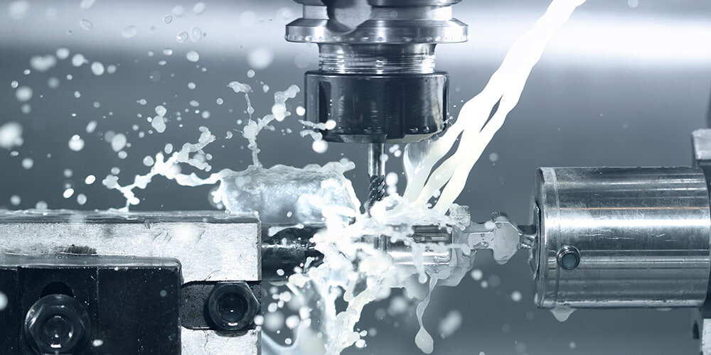
Coolant requirements vary dramatically by material. Aluminum machines well with flood coolant or mist systems, though some high-speed operations run dry. Stainless steel absolutely requires effective cooling to manage heat and extend tool life. Titanium demands high-pressure coolant—often delivered through the tool itself—to evacuate chips and cool the cutting zone effectively. VMT specifically recommends "high-pressure coolant systems" that "effectively evacuate chips, reduce cutting temperature, and prevent chip adhesion."
Plastics represent the exception: many engineering polymers machine better with air blast cooling rather than liquid coolants, which can cause thermal shock or leave residues requiring additional cleaning.
Chip management considerations also differ by material:
- Aluminum: Produces continuous chips that can wrap around the workpiece; chip breakers and appropriate speeds help
- Steel: Forms manageable chips with proper insert geometry selection
- Stainless steel: Tough, stringy chips require aggressive chip breaking strategies
- Titanium: According to VMT, tends to "produce continuous chips" that require specialized drill geometries for evacuation
- Brass: Creates small, easily managed chips—one reason it's favored for screw machine work
Understanding these material-specific behaviors transforms your precision cnc lathe from a general-purpose tool into an optimized production asset. But even with perfect material knowledge, questions remain about when CNC lathing offers genuine advantages over manual turning—and when milling might serve your needs better.
CNC Lathing Versus Manual Turning and Milling Operations
Here's the productivity question nobody wants to answer honestly: how much efficiency are you leaving on the table with manual turning? The gap between CNC and conventional lathe operations isn't just about automation—it's about fundamental differences in accuracy, consistency, and throughput that compound with every part you produce. Understanding these differences helps you make informed decisions about equipment investments, outsourcing strategies, and production planning.
But the comparison doesn't stop at manual versus CNC. Many manufacturers also wonder when a lathe serves better than a mill—or whether hybrid mill turn machines might eliminate the need to choose at all. Let's examine each comparison with the specific metrics that actually matter for production decisions.
Quantifying the Precision Advantage of CNC Control
When comparing CNC and lathe operations in manual versus automated configurations, the numbers tell a compelling story. According to industry data from CNC Yangsen, CNC lathes achieve accuracy levels of 0.001mm, while conventional lathes typically show deviations of 0.01mm depending on operator skill and environmental factors. That's a tenfold difference in precision capability.
Why does this gap exist? Consider the sources of error in each approach:
- Human variability: Manual operations depend on operator fatigue, attention, and technique—factors that fluctuate throughout a shift
- Environmental sensitivity: Temperature changes, vibrations, and humidity affect conventional lathes more significantly because operators cannot compensate as precisely as CNC sensors
- Calibration consistency: CNC systems maintain calibrated movements programmatically, while manual adjustments introduce cumulative errors
- Repeatability: Programming ensures identical toolpaths on every cycle; manual replication depends entirely on human memory and skill
The repeatability advantage deserves special emphasis. Imagine producing 500 identical shafts. On a conventional lathe, each part depends on the operator's ability to replicate exact movements, wheel positions, and cutting depths. Even skilled machinists introduce variation. CNC control eliminates this variability—part 500 matches part 1 with programmatic precision.
According to manufacturing studies cited by CNC Yangsen, aerospace applications using CNC lathes achieve accuracy of 0.002mm, meeting stringent industry requirements. Conventional machines producing similar components show accuracy around 0.01mm—acceptable for some applications but insufficient for flight-critical parts.
Production Efficiency Gains That Transform Operations
Precision alone doesn't justify equipment investments. The productivity differential between manual and CNC operations extends across multiple dimensions that directly impact your bottom line.
| Performance Metric | Manual/Conventional Lathe | CNC Lathe | Advantage Factor |
|---|---|---|---|
| Tolerance Capability | ±0.01mm (skill-dependent) | ±0.001mm (consistent) | 10x tighter tolerances |
| Setup Time (new job) | 30-60 minutes typical | 15-30 minutes with stored programs | 50% reduction |
| Per-Part Consistency | Variable; operator-dependent | Identical within machine capability | Eliminates part-to-part variation |
| Production Speed | Moderate; limited by manual feed rates | Optimized; programmed for efficiency | 30% faster cycle times typical |
| Operator Dependency | High; requires continuous skilled attention | Low; one operator can monitor multiple machines | 50% labor cost reduction potential |
| Scrap Rate | Higher; human error accumulates | Lower; consistent execution reduces waste | Significant material savings |
| Complex Geometry Capability | Limited by operator skill | Handles intricate profiles programmatically | Enables designs impossible manually |
The labor economics alone transform operational planning. According to CNC Yangsen's industry analysis, CNC lathes reduce labor costs by approximately 50%, with a 25-40% increase in overall production. A manufacturing association study indicates that CNC technology adoption has led to 20-50% productivity improvements over five-year periods.
These gains compound in high-volume production. When you're producing thousands of parts, the consistency advantage eliminates rework, reduces inspection burden, and enables statistical process control that simply isn't feasible with manual variability.
When does manual turning still make sense? Conventional lathes retain advantages in specific scenarios:
- One-off repairs: Quick fixes where programming time exceeds machining time
- Prototype exploration: Initial concept development where specifications change rapidly
- Simple, low-precision parts: Applications where ±0.1mm tolerance suffices
- Training environments: Teaching fundamental machining principles before CNC exposure
- Artistic or custom work: Pieces requiring human judgment and aesthetic decisions
However, for production manufacturing where consistency, throughput, and precision matter, CNC control delivers measurable advantages that manual operations simply cannot match.
CNC Mills and Lathes: Understanding When Each Applies
Beyond the manual versus CNC comparison, manufacturers frequently question whether mills and lathes serve interchangeable purposes. The short answer: they don't. Understanding the fundamental difference prevents costly equipment mismatches.
CNC lathes excel at producing cylindrical, conical, and helical geometries. The workpiece rotates while cutting tools approach from fixed positions. This configuration naturally produces:
- Shafts and spindles
- Bushings and bearings
- Threaded fasteners
- Tapered components
- Spherical and contoured surfaces of revolution
CNC mills handle prismatic geometries—parts with flat surfaces, pockets, and features that don't require rotation. According to Machine Station's technical analysis, mills and lathes serve fundamentally different purposes based on part geometry. Mills rotate the cutting tool while the workpiece remains stationary (or indexes), producing:
- Rectangular blocks and housings
- Pocketed components
- Parts with multiple flat faces
- Complex 3D sculptured surfaces
Can a mill replace a lathe? For some operations—yes, with 4th-axis rotary capability, a mill can perform turning-like operations. But it's rarely optimal. The inherent rigidity of a dedicated lathe, the efficiency of continuous rotation, and the tooling designed specifically for turning operations mean that CNC mills and lathes each perform their intended functions more efficiently than either attempting the other's specialty.
Mill-Turn Machines: The Hybrid Solution
What happens when your parts require both turning and milling operations? Traditionally, manufacturers transferred workpieces between machines—introducing handling time, alignment challenges, and potential for error at each transition.
Mill turn machines—also called turn mill machines or multitasking lathes—combine both capabilities in a single setup. These hybrid configurations integrate driven (rotating) milling tools with standard turning capability, enabling:
- Turned diameters with cross-drilled holes
- Shafts featuring milled flats or keyways
- Components requiring both cylindrical and prismatic features
- Parts with off-center machining requirements
A cnc mill lathe configuration—sometimes described as a lathe with mill capability—represents significant investment but delivers compelling advantages for complex parts. Consider a transmission shaft requiring turned bearing journals, milled splines, and cross-drilled oil passages. On separate machines, this part requires three setups with alignment verification at each. On a mill and lathe machine combination, everything completes in one clamping.
The productivity impact is substantial:
- Eliminated transfer time: No workpiece movement between machines
- Reduced setup errors: Single clamping maintains alignment throughout all operations
- Smaller footprint: One machine replaces two or more
- Simplified scheduling: No queue dependencies between separate operations
However, mill-turn machines carry premium price tags and require operators skilled in both turning and milling principles. For shops with simpler part requirements, dedicated CNC lathes and mills often provide better value than hybrid configurations.
The productivity gap between manual and CNC operations is real and measurable—but so are the differences in maintenance requirements, troubleshooting complexity, and operational knowledge needed to keep these machines performing at their potential.
Troubleshooting and Maintaining Your CNC Lathe
Your CNC lathe ran perfectly yesterday—so why are today's parts showing chatter marks and dimensional drift? Most CNC issues stem from a few common causes: mechanical wear, programming errors, or neglected maintenance. According to Tools Today's troubleshooting guide, knowing the warning signs and acting early saves time, tools, and money. Let's explore the practical diagnostic steps that keep your lathe machines producing quality parts consistently.
Diagnosing Common CNC Lathe Problems Before They Escalate
When surface finish deteriorates or dimensions start wandering, experienced operators don't panic—they diagnose systematically. Here are the most frequent issues you'll encounter and their root causes.
Chatter and vibration announce themselves through distinctive witness marks on the workpiece surface—regular patterns of ridges that ruin finish quality. Common culprits include:
- Worn lathe tool bits: Dull or chipped cutting edges create inconsistent cutting forces
- Improper tool overhang: Excessive extension from the turret amplifies vibration
- Loose workholding: Insufficient chuck pressure allows the workpiece to shift under cutting forces
- Worn spindle bearings: Degraded bearings introduce play that manifests as chatter
- Aggressive cutting parameters: Depths of cut or feed rates exceeding machine rigidity limits
Surface finish problems beyond chatter often trace to cutting parameter mismatches. When aluminum parts show smearing instead of clean cuts, your speeds are likely too low—causing built-up edge on the tool. When steel parts display rough finishes despite sharp tooling, feed rates may exceed what the insert nose radius can handle smoothly.
Dimensional drift during production runs signals thermal expansion or mechanical wear. As lathes machinery heats during operation, spindle growth can shift dimensions by several hundredths of a millimeter. According to industry troubleshooting resources, backlash and overheating often stem from neglected maintenance—particularly lubrication systems that fail to adequately cool and protect moving components.
Tool wear patterns tell their own diagnostic story:
- Flank wear: Normal progression; indicates appropriate parameters
- Crater wear: Excessive heat at the cutting zone; reduce speed or improve coolant
- Notch wear: Work-hardened material or depth-of-cut line issues
- Chipping: Interrupted cuts, excessive feed, or inadequate tool grade for material
Spindle issues represent serious concerns requiring immediate attention. Warning signs include unusual noise during rotation, excessive heat at the headstock, or gradual loss of surface finish quality. Machine lathes depend entirely on spindle health—when bearings degrade, every part suffers.
Preventive Maintenance Schedules That Maximize Uptime
Reactive maintenance costs more than prevention—in downtime, scrap, and emergency repair premiums. According to Haas CNC's maintenance documentation, structured maintenance programs allow you to manage your schedule rather than getting caught with untimely surprises.
Warning signs operators should monitor daily:
- Unusual sounds during spindle acceleration or deceleration
- Chips or coolant accumulating in unexpected areas
- Lubrication level indicators showing low conditions
- Hydraulic pressure readings outside normal ranges
- Axis movement hesitation or roughness during jogging
- Coolant concentration or contamination changes
- Chuck clamping pressure variations
Recommended maintenance intervals for lathes machines:
Daily tasks:
- Clean chips and debris from the work zone and way covers
- Verify coolant levels and concentration
- Check lubrication system indicators
- Wipe down guideways and exposed precision surfaces
Weekly tasks:
- Inspect and clean coolant filters
- Check hydraulic fluid levels
- Verify chuck jaw condition and clamping consistency
- Clean turret tool pockets and indexing surfaces
Monthly tasks:
- Grease tailstock components per manufacturer specifications
- Inspect spindle bearing temperature patterns
- Check way lubrication distribution
- Verify axis backlash compensation accuracy
Quarterly/annual tasks:
- Professional spindle bearing inspection
- Ball screw condition assessment
- Complete coolant system flush and refill
- Controller backup and software verification
As Tools Today emphasizes, encoder problems, shorted wires, or controller issues should be handled by licensed technicians. Similarly, bed leveling, ball screw replacement, and servo tuning require experienced CNC service professionals with access to OEM diagnostic software.
A well-maintained lathes machine is a productive machine—but even perfect maintenance doesn't eliminate the capital investment required to bring CNC capability in-house. Understanding the true cost of ownership helps you decide whether equipment purchase or outsourced manufacturing better serves your production needs.
Cost Considerations and Sourcing Strategies for CNC Lathing
You've seen the productivity advantages and precision capabilities—but what does a CNC lathe actually cost? This question trips up many manufacturers because the sticker price tells only part of the story. According to CNC Cookbook's comprehensive cost analysis, the factors driving CNC machine cost range from machine size and axis count to brand reputation and controller sophistication. Understanding these variables—and the ongoing expenses that follow—helps you make investment decisions that actually pay off.
Investment Considerations Beyond the Purchase Price
When you see a CNC lathe for sale, the advertised cnc lathe price represents just the starting point. Multiple factors determine where any specific machine falls within the broad pricing spectrum.
Machine size and work envelope dramatically impact cost. According to CNC Cookbook, machine size—typically measured as the work envelope (X, Y, and Z coordinate range)—is a huge determiner of machine cost. Compact benchtop units suitable for small parts occupy one end of the spectrum, while floor-standing machines capable of handling heavy shafts command premium pricing.
Axis count and configuration add complexity that directly correlates with price. A basic 2-axis lathe costs significantly less than multi-axis configurations. CNC Cookbook notes that "more axes make a machine more powerful, but they can also rapidly add complexity that drives up the cost." CNC lathes are often cheaper than equivalent CNC mills simply because turning operations start with fewer axes than milling operations.
Controller sophistication separates entry-level machines from production-grade equipment. Premium controllers from Fanuc, Siemens, or Haas offer advanced programming capabilities, better diagnostics, and higher precision—at correspondingly higher prices. The controller essentially determines what the machine can do and how accurately it performs.
Brand reputation and origin influence both initial cost and long-term support expectations. According to CNC Cookbook, machine origin—whether Asia (China, Korea, Taiwan, or Japan), Europe, or the US—affects pricing structures and available support networks.
Here's what realistic first-year investments look like across different capability levels, based on industry benchmarking data:
| Investment Level | Equipment Cost | First-Year Total (All-In) | Best Suited For |
|---|---|---|---|
| Entry-Level (3-Axis) | $50,000-$120,000 | $159,000-$286,000 | Job shops, low-volume production |
| Production-Grade | $100,000-$250,000 | $250,000-$450,000 | Medium-volume manufacturing |
| Professional (5-Axis) | $300,000-$800,000 | $480,000-$1,120,000 | Aerospace, complex geometries |
Why does the first-year total far exceed equipment cost? According to Rivcut's analysis, equipment cost represents only about 40% of total investment—operator costs, facility requirements, and tooling add the remaining 60%.
Calculating True Cost of Ownership for CNC Lathes
The cost of cnc lathe machine ownership extends well beyond the purchase invoice. Ongoing expenses accumulate throughout the machine's operational life, and underestimating them leads to budget shortfalls and operational headaches.
Tooling and consumables represent continuous expenditure. According to CNC Cookbook, you should plan to budget as much as you paid for the CNC machine to purchase all of the rest of the items necessary—tooling, workholding, inspection equipment, and CAM software. At minimum, budget at least half as much as the machine cost for these essential additions.
Maintenance costs for CNC lathes typically range from $1,000 to $5,000 annually for routine servicing, according to Machine Tool Specialties' cost breakdown. Additional expenses for consumables and software updates can add 10-25% to total operating costs. CNC Cookbook recommends budgeting 8-12% of equipment value annually for maintenance on professional-grade machinery.
Training investment affects both startup timeline and operational efficiency. Specialized CNC operator training typically costs $2,000-$5,000 per operator. More significantly, Rivcut's analysis identifies a 12-18 month learning curve that results in 40-60% material waste and 2-3x longer cycle times versus experienced operators. This "tuition" often costs $30,000-$80,000 in wasted material and lost productivity—expenses that rarely appear in ROI calculations.
Energy consumption adds ongoing operational expense. CNC machines draw significant power during operation, with larger spindle motors and high-speed operations consuming more electricity. Optimizing cycle times and implementing sleep mode functions can reduce CNC energy expenses by as much as 30%, according to industry data.
Facility requirements often surprise first-time buyers. Heavier machines require special crews for installation ("rigging"), specific electrical configurations, and potentially compressed air systems. Phase converters for home shops, climate control for precision work, and adequate floor space all add costs that must be budgeted upfront.
New, Used, or Refurbished: Making the Right Choice
The pre-owned market presents substantial savings opportunities, though pricing varies considerably based on age, condition, and maintenance history. A cnc used lathe or cnc lathe used from a reputable dealer can conserve initial capital while delivering capable performance.
When evaluating a used lathe or browsing cnc lathes for sale listings, consider these key decision factors:
- Documented maintenance history: Machines with complete service records present lower risk than those with unknown backgrounds
- Spindle hours and condition: Spindle health determines achievable precision; worn bearings require expensive replacement
- Controller generation: Older controllers may lack features, parts availability, or software support
- Available support: Can you source replacement parts? Does the original manufacturer still support this model?
- Accuracy verification: Request ball bar testing or laser calibration reports before purchase
- Electrical compatibility: Verify voltage and phase requirements match your facility
- Warranty or guarantee terms: Reputable dealers offer limited warranties even on used equipment
According to Machine Tool Specialties, opting for a used CNC lathe can conserve initial capital but might lead to increased short-term maintenance needs. Conversely, a meticulously maintained machine often requires minimal retrofitting and delivers years of reliable service.
The Outsourcing Alternative: Accessing Capability Without Capital Risk
Here's a question worth considering: does your production actually require owning CNC equipment, or do you need CNC lathing capability?
According to Rivcut's manufacturing strategy analysis, for volumes under 300 parts annually, outsourcing typically delivers 40-60% lower total cost when factoring in all hidden expenses, faster time-to-market, and reduced risk. The break-even point for moderate complexity parts sits at 500-800 parts per year over 3-4 years.
Outsourcing CNC lathing eliminates several cost categories entirely:
- Zero capital investment: No $150,000-$450,000 upfront equipment purchase
- No learning curve waste: Professional shops already have experienced operators
- Eliminated maintenance burden: Equipment upkeep becomes the supplier's responsibility
- Instant scalability: Volume fluctuations don't require equipment additions
- Access to expertise: DFM (Design for Manufacturing) support prevents costly redesigns
Professional shops deliver parts in 1-3 days versus the weeks or months required to set up in-house capabilities. For time-sensitive prototyping or production, this speed advantage often justifies per-part premiums by enabling faster product development cycles.
For automotive applications demanding stringent quality standards, IATF 16949 certified suppliers like Shaoyi Metal Technology offer an alternative path—accessing precision CNC lathing capabilities through outsourced manufacturing rather than capital equipment investment. With lead times as fast as one working day and Statistical Process Control (SPC) ensuring consistent quality, manufacturers can scale from rapid prototyping to mass production for chassis assemblies and custom metal components without the overhead of equipment ownership. Explore outsourced CNC machining solutions at Shaoyi's automotive machining services.
Whether you pursue equipment ownership or manufacturing partnerships, understanding the complete cost picture—initial investment, ongoing expenses, hidden costs, and alternatives—ensures your decision supports long-term operational success rather than creating financial strain.
Taking Your Next Steps in CNC Lathe Manufacturing
You've explored what is cnc lathe technology, examined machine components, compared configurations, and calculated costs—now what? The path forward depends entirely on your specific situation: production volumes, part complexity, quality requirements, and timeline constraints. Whether you're a hobbyist exploring precision turning, a job shop expanding capabilities, or a production manufacturer scaling operations, your next steps should align with your actual needs rather than aspirational equipment purchases.
Building Your CNC Lathing Strategy for Success
Before committing capital or signing supplier contracts, answer four critical questions that determine the right approach for your operation.
What are your volume requirements? As established in our cost analysis, the break-even point for in-house CNC lathing typically falls between 500-800 parts annually over a 3-4 year period. Below this threshold, outsourcing generally delivers better economics. Above it, equipment ownership becomes increasingly attractive—assuming you have the expertise to operate efficiently.
How complex are your parts? Simple cylindrical components suit basic 2-axis CNC lathe machines, while parts requiring milled features, off-center drilling, or compound angles demand multi-axis configurations or mill-turn capabilities. Mismatching equipment to part requirements wastes capital on unnecessary capability—or leaves you unable to produce what you need.
What quality standards must you meet? According to American Micro Industries' certification guide, certified professionals and processes support the precision and consistency that modern manufacturing demands. For automotive applications, IATF 16949 certification provides the global standard for quality management, combining ISO 9001 principles with sector-specific requirements for continuous improvement and defect prevention. Medical device manufacturing requires ISO 13485 compliance, while aerospace demands AS9100 certification.
How quickly do you need production capability? Building in-house expertise takes 12-18 months to reach efficient operation, according to industry benchmarks. Outsourcing to established suppliers provides immediate access to production-ready capability—often with lead times measured in days rather than months.
Next Steps Toward Precision Manufacturing Excellence
Your path forward differs based on your operational context. Here's practical guidance tailored to each scenario.
For hobbyists and makers:
- Start with benchtop CNC turning lathe units in the $3,000-$15,000 range to learn fundamentals without major capital risk
- Focus on aluminum and brass initially—forgiving materials that build confidence before tackling steel or stainless
- Invest in CAM software training before purchasing equipment; programming skill matters more than machine sophistication
- Join online communities and local makerspaces to accelerate learning and access shared resources
- Consider manual lathe experience first to understand turning principles before adding CNC complexity
For job shops expanding capabilities:
- Evaluate your current job mix to identify which parts would benefit most from CNC turning capability
- Consider used or refurbished equipment from reputable dealers to reduce initial investment while testing market demand
- Calculate true ROI including operator training, tooling investment, and the 12-18 month learning curve productivity impact
- Develop relationships with industrial lathe service providers for backup capacity during equipment downtime or demand spikes
- Pursue relevant certifications—ISO 9001 at minimum—to access customers requiring documented quality systems
For production manufacturers:
- Conduct make-versus-buy analysis for each part family, considering total cost of ownership rather than per-part quotes alone
- For automotive applications, prioritize suppliers with IATF 16949 certification and demonstrated Statistical Process Control (SPC) implementation
- Establish dual-source strategies that balance in-house capability with qualified external partners for surge capacity
- Invest in automation—bar feeders, parts catchers, and lights-out capability—to maximize equipment utilization
- Implement preventive maintenance programs that protect your capital investment and ensure consistent quality
The application of cnc lathe machine technology spans virtually every manufacturing sector, but success depends on matching your approach to your actual requirements. What is cnc lathe capability worth if you're paying for features you'll never use? Conversely, underinvesting in equipment or supplier relationships creates quality problems that damage customer relationships.
For readers seeking immediate production capacity without capital investment, certified manufacturing partners offer a compelling alternative. Shaoyi Metal Technology's precision CNC machining services scale seamlessly from rapid prototyping to mass production, backed by IATF 16949 certification and strict Statistical Process Control. Whether you need complex chassis assemblies or custom metal components, their facility delivers high-tolerance parts with lead times as fast as one working day. Explore reliable manufacturing solutions at Shaoyi's automotive machining services.
The productivity gap between manual turning and CNC lathing is real—but so is the gap between strategic equipment decisions and impulsive purchases. Armed with the knowledge from this guide, you're equipped to make choices that deliver genuine competitive advantage rather than expensive lessons. Your next step? Define your requirements clearly, evaluate your options honestly, and move forward with confidence toward precision manufacturing excellence.
Frequently Asked Questions About CNC Lathing
1. What is CNC lathing?
CNC lathing is a subtractive machining process where computer numerical control guides cutting tools to remove material from a rotating workpiece. Unlike manual turning that relies on operator skill, CNC lathes follow programmed G-code instructions to create precise cylindrical, conical, and helical shapes with tolerances as tight as ±0.005mm. This technology powers critical manufacturing across automotive, aerospace, and medical device industries.
2. What is lathing in machining?
Lathing refers to rotational machining where the workpiece spins while stationary cutting tools shape it. Operations include turning (reducing diameter), facing (creating flat surfaces), grooving, threading, and boring. CNC lathing automates these operations through digital programming, eliminating human variability and enabling complex geometries impossible with manual techniques.
3. What is the difference between CNC lathing and CNC milling?
CNC lathes rotate the workpiece while cutting tools remain stationary, making them ideal for cylindrical parts like shafts and bushings. CNC mills rotate the cutting tool while the workpiece stays fixed, excelling at prismatic geometries with flat surfaces and pockets. Mill-turn machines combine both capabilities for complex parts requiring both turning and milling operations in a single setup.
4. How much does a CNC lathe machine cost?
CNC lathe prices range from $50,000-$120,000 for entry-level 3-axis machines to $300,000-$800,000 for professional 5-axis configurations. However, first-year total costs including tooling, training, and facility requirements can reach 1.5-2x the equipment price. For manufacturers producing under 500 parts annually, outsourcing to IATF 16949 certified suppliers often delivers 40-60% lower total cost.
5. What materials can be machined on a CNC lathe?
CNC lathes machine metals including aluminum (fastest cutting speeds), steel, stainless steel, titanium, brass, and bronze. Engineering plastics like Delrin and PEEK require sharp tooling to prevent melting. Each material demands specific cutting parameters—aluminum allows speeds of 200-400 m/min while titanium requires only 60-90 m/min due to heat concentration at the cutting edge.