 Small batches, high standards. Our rapid prototyping service makes validation faster and easier —

From Blueprint To Factory Floor: How CNC Machine Manufacturing Really Works
Understanding CNC Machine Manufacturing and Why It Matters
Every smartphone in your pocket, every aircraft soaring overhead, and every medical implant saving lives shares something in common: they were shaped by machines so precise they can work within tolerances thinner than a human hair. But here's the question few people ask—who builds these remarkable machines?
When you search for information about CNC machine manufacturing, you'll find countless articles about using CNC machines to cut parts. That's CNC machining services. What we're exploring here is fundamentally different: the actual process of designing, engineering, and assembling the computer numerical control machines themselves. So, what is CNC in this context? It refers to Computer Numerical Control—the technology that allows machines to execute precise movements based on digital instructions.
Understanding what does CNC stand for is just the starting point. The real story lies in how these sophisticated pieces of equipment come to life, from initial concept sketches to fully operational machines ready for factory floors worldwide.
From Blueprint to Production Floor
Imagine the journey of a CNC machine before it ever cuts its first piece of metal. It begins as an idea shaped by market research and engineering calculations. Manufacturers study what industries need—whether that's aerospace companies demanding five-axis capability or medical device makers requiring micron-level precision.
The CNC meaning extends far beyond simple automation. According to industry experts, this machining manufacturing process involves careful planning at every stage. Engineers use CAD software to create detailed 3D models of every component, from massive cast iron frames to tiny ball bearings. They run virtual stress tests and motion simulations before a single piece of metal is cut.
This conceptual phase is where quality begins. A manufacturer that rushes through design—skipping stress analysis or prototype testing—produces machines that struggle under real production conditions. The best CNC machine manufacturers invest months in refining designs before moving to fabrication.
The Machines Behind the Machines
Why does machine manufacturing at this level matter? Consider this: every CNC machine in operation today was built by another precision manufacturing system. It's machines all the way down. The quality of your CNC equipment directly depends on the capabilities of the manufacturer who built it.
"A CNC machine is only as good as its weakest component. If any critical part isn't machined with care, the entire machine suffers—and so does every product it creates."
This insight captures why understanding CNC machine manufacturing is essential for two distinct audiences. First, engineers and manufacturing professionals seeking to understand how these complex systems work. Second, procurement specialists evaluating potential suppliers for major equipment purchases.
The CNC definition that matters here encompasses the entire ecosystem: precision casting of machine bases, grinding of ways and surfaces, assembly procedures requiring geometric calibration, and rigorous quality testing. Each step demands expertise that separates reliable industrial equipment from machines that create headaches.
As precision manufacturing continues evolving with technologies like IIoT and AI-driven analytics, the machines enabling this revolution must themselves be manufactured to increasingly demanding standards. Whether you're looking to understand the process or evaluate manufacturers for procurement, the chapters ahead will take you through every stage of how CNC machines are truly made.
Evolution from NC to Modern CNC Technology
How did we get from skilled machinists manually cranking handwheels to machines that can run unattended for 24 hours straight? The answer involves punch cards, Cold War funding, and a Mickey Mouse ashtray. Understanding this evolution isn't just historical trivia—it helps you appreciate why modern CNC machines work the way they do and what capabilities you should expect when evaluating equipment today.
The journey from manual to numerical control machine technology began with a fundamental problem: human operators, no matter how skilled, couldn't consistently reproduce the same precise movements thousands of times. The machining meaning shifted from pure craftsmanship to programmable precision.
The Punch Tape Era and Early Automation
In 1946, John Parsons and Frank Stulen were working on helicopter rotor blades for Sikorsky Aircraft. They faced a challenge—cutting complex curved surfaces that required perfect consistency. Stulen's brother worked at IBM with punch card readers, sparking an idea. What if machines could follow coded instructions instead of relying on human hand-eye coordination?
Their early prototype was surprisingly labor-intensive. One operator would call out coordinates from a chart while two others manually adjusted the X and Y axes. But Parsons saw something bigger: what if the punch cards could control the machine directly?
The U.S. Air Force recognized the potential and funded MIT's Servomechanisms Laboratory with a $200,000 contract (roughly $2.5 million today). By 1952, MIT demonstrated the first working NC system on a retrofitted Cincinnati milling machine—using punch tape instead of cards for faster data input.
Here are the key technological milestones that shaped early NC and CNC machine development:
- 1949: U.S. Air Force funds MIT to develop numerical control technology
- 1952: First working NC machine demonstrated at MIT; Arma Corporation announces first commercial NC lathe
- 1955-1959: Commercial NC machines from Bendix and Kearney & Trecker enter the market
- 1959: APT (Automatically Programmed Tools) language presented—the foundation for modern G-code
- 1960s: Transistors replace vacuum tubes, making NC machines smaller and more reliable
- 1970: First microprocessors enable true computer numerical control
- 1976: Fanuc releases Model 2000C—widely considered the first modern CNC controller
Early NC machines had serious limitations. Creating punch tapes was almost as time-consuming as the machining itself. A task that took 8 hours to machine might require equal time just to produce the tape. Some historians note this actually served certain purposes—moving programming work from unionized factory floors to design offices.
Digital Revolution in Machine Control
The real transformation came when computers replaced punch tape entirely. During MIT's Whirlwind Navy Computer project, engineer John Runyon discovered that real-time computer control could slash programming time from 8 hours to 15 minutes. This breakthrough pointed toward the future of types of computer numerical control systems.
By the 1970s, microprocessors made computers small enough and affordable enough for factory floors. Companies like Fanuc, Siemens, and Allen-Bradley launched controllers that offered flexibility impossible with paper-based systems. Operators could modify programs on the fly, store multiple part programs, and achieve precision that punch tape couldn't match.
The 1980s and 1990s brought CAD/CAM integration—engineers could design parts digitally and automatically generate toolpaths. Multi-axis machines appeared, allowing complex geometries in single setups. What once required multiple operations on different machines could now happen in one clamping.
Why does this history matter for today's buyers and manufacturers? Because the NC and CNC machine evolution reveals what truly drives quality: control system sophistication, programming flexibility, and the ability to maintain precision over millions of cycles. When you evaluate a modern NC CNC machine or even a computer numerical control router, you're looking at technology refined through seven decades of continuous improvement.
The progression from punch tape to AI-assisted toolpath optimization follows a clear logic—each generation solved problems the previous one couldn't. Today's CNC machines with IoT connectivity and digital twin capabilities exist because engineers kept pushing boundaries that started with Parsons and Stulen's helicopter blade project. And with these control systems now established, the next question becomes: what physical components translate digital commands into actual cutting action?
Critical Components That Power CNC Machines
You've seen how punch tape evolved into sophisticated digital control systems. But here's the thing—those control signals are useless without physical components capable of translating digital commands into micron-precise movements. What actually makes a CNC machine move, cut, and hold tolerances that would have seemed impossible to machinists a generation ago?
Every CNC device consists of interconnected systems working in harmony. When any single component falls short, the entire machine suffers. Understanding these CNC parts isn't just academic—it's essential knowledge for anyone evaluating CNC equipment purchases or troubleshooting performance issues.
Motion Systems and Precision Mechanics
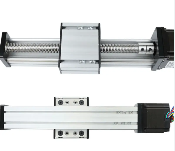
Imagine trying to position a cutting tool within 0.001 millimeters—roughly 1/70th the width of a human hair. That's what motion systems accomplish thousands of times per machining cycle. Two components make this possible: ball screws and linear guides.
Ball screws convert rotational motion from motors into linear movement. Unlike standard lead screws that use sliding contact, ball screws use recirculating steel balls between the screw shaft and nut. This rolling contact reduces friction by up to 90%, enabling higher speeds with less heat generation. Precision ball screws are ground—not rolled—to achieve positioning accuracies of ±0.004mm per 300mm of travel.
Where do these critical CNC parts come from? Japan dominates high-precision ball screw manufacturing, with companies like THK and NSK supplying premium machines worldwide. Taiwan produces mid-range options, while Chinese manufacturers increasingly compete in both segments. The grinding process requires specialized equipment itself—creating a fascinating supply chain where precision machinery builds precision machinery.
Linear guides (also called linear rails) support and constrain axis movement. They must handle substantial cutting forces while maintaining smooth, accurate travel. Premium guides use recirculating ball or roller bearings within precision-ground rails. The contact geometry determines load capacity, rigidity, and lifespan.
Here's what separates good motion systems from great ones: preload. Manufacturers apply controlled tension between balls and raceways to eliminate play. Too little preload allows backlash that destroys accuracy. Too much creates friction and premature wear. Getting this balance right requires engineering expertise and quality control that entry-level manufacturers often lack.
Control Architecture and Electronics
The brain of any CNC machine is its controller—the electronic system that interprets G-code programs and orchestrates all machine functions. Modern CNC control systems from Fanuc, Siemens, Heidenhain, and Mitsubishi represent decades of refinement. They process millions of calculations per second to coordinate multi-axis movements with spindle operations and coolant flow.
Controllers don't work alone. They communicate with servo motors and drives that power each axis. Unlike simple stepper motors (which move in fixed increments and can lose position under load), servo systems use closed-loop feedback. Encoders mounted on motors and sometimes directly on axis components continuously report actual position back to the controller.
This feedback loop enables remarkable precision. If cutting forces push an axis slightly off course, the servo system detects the error and corrects immediately—often within milliseconds. High-end machines use glass scale encoders with 0.0001mm resolution mounted directly on each axis, providing absolute position confirmation independent of motor feedback.
The CNC tools ecosystem also includes auxiliary controls for tool changers, pallet systems, chip conveyors, and coolant pumps. Integration quality matters enormously. A machine might have excellent axis components but suffer from poorly implemented tool changer logic that creates positioning errors during automated operation.
Spindle Technology and Power Transmission
If motion systems position the CNC tool, the spindle does the actual work. This rotating component holds cutting tools and delivers the power needed to remove material. Spindle quality directly determines what materials you can cut, how fast you can cut them, and what surface finishes you'll achieve.
According to industry experts, CNC spindle motors are high-performance, torque-dense motors designed for computer numerically controlled machinery. These motors can achieve high speeds and torque levels while maintaining accuracy through precision bearings and specially designed rotors. The rotor spins while precision bearings support it at either end, and the interaction between stator windings and rotor allows speeds up to 20,000 RPM or higher while maintaining precision.
Two main spindle motor types dominate CNC equipment:
- AC induction motors: The most common choice due to low cost and reliability. They're rugged and well-suited to industrial applications where consistent performance matters more than maximum speed.
- Brushless DC motors: Increasingly popular in high-end applications where speed and precision are paramount. Without brushes, they reduce friction and increase reliability for demanding operations.
Spindle bearings represent another critical CNC part affecting performance. Angular contact bearings arranged in sets provide the rigidity needed for heavy cutting while ceramic hybrid bearings enable higher speeds with reduced heat. Bearing preload, lubrication systems, and thermal management all influence how long a spindle maintains its accuracy.
Below is a comprehensive comparison of major CNC machine components:
| Component | Primary Function | Precision Requirements | Typical Manufacturing Origins |
|---|---|---|---|
| Ball Screws | Convert rotational to linear motion | ±0.004mm per 300mm (precision grade) | Japan (THK, NSK), Taiwan, Germany |
| Linear Guides | Support and constrain axis movement | ±0.002mm straightness per meter | Japan, Taiwan, Germany (Bosch Rexroth) |
| Servo Motors | Power axis movement with feedback | Encoder resolution to 0.0001mm | Japan (Fanuc, Yaskawa), Germany (Siemens) |
| CNC Controllers | Process programs and coordinate systems | Nanometer interpolation capability | Japan (Fanuc), Germany (Siemens, Heidenhain) |
| Spindles | Hold tools and deliver cutting power | Runout under 0.002mm | Switzerland, Germany, Japan, Italy |
| Tool Changers | Automate tool selection and exchange | Repeatability within 0.005mm | Japan, Taiwan, domestic to machine builder |
Understanding this component breakdown reveals why CNC machines at different price points perform so differently. A budget machine might use rolled ball screws instead of ground ones, stepper motors instead of servos, or spindle bearings with wider tolerances. Each compromise affects accuracy, speed capability, and longevity.
When evaluating CNC equipment, asking about component sourcing tells you volumes about build quality. Manufacturers using premium Japanese motion components and German or Japanese controllers are investing in performance. Those keeping component origins vague may be cutting corners that show up as problems months into production.
With these critical components explained, the next logical question becomes: how do different combinations of these parts create the various machine types you'll encounter—from simple 3-axis mills to complex multi-axis turning centers?
Types of CNC Machines and Their Manufacturing Applications
Now that you understand what components make CNC machines work, here's the natural next question: how do manufacturers combine these parts into different machine types? The answer depends entirely on what you need to produce. A shop making flat aluminum plates has vastly different requirements than one crafting titanium aerospace components with compound curves.
The types of CNC machines available today range from straightforward 3-axis mills to sophisticated multi-axis systems capable of machining complex geometries in single setups. Understanding these configurations helps you match equipment to applications—whether you're evaluating manufacturers or planning production capacity.
Milling Machines and Vertical Machining Centers
When most people picture CNC equipment, they're imagining a milling machine. CNC mills use rotating cutting tools to remove material from stationary workpieces. The spindle moves relative to the part, carving away metal, plastic, or composite materials layer by layer.
Vertical machining centers (VMCs) position the spindle vertically—pointing downward toward the workpiece. This configuration excels at flat surfaces, pockets, and features on the top of parts. Gravity helps with chip evacuation, and operators can easily see what's happening during cutting.
A standard 3-axis VMC moves the cutting tool along X (left-right), Y (front-back), and Z (up-down) directions. According to AMFG's comprehensive guide, these machines are well-suited for simpler, flat, and less intricate cuts—ideal for creating straightforward molds or basic components like rectangular plates.
Horizontal machining centers (HMCs) rotate the spindle 90 degrees, positioning it parallel to the floor. This orientation offers advantages for certain applications:
- Better chip evacuation—gravity pulls chips away from the cutting zone
- Superior rigidity for heavy cuts on large workpieces
- Easier access to multiple sides of box-shaped parts
- Often equipped with pallet changers for continuous production
CNC milling machines handle an enormous range of materials and applications. From prototyping shops cutting aluminum housings to production facilities machining hardened steel dies, the cnc mill machine remains the workhorse of subtractive manufacturing.
Turning Centers and Swiss-Type Precision
While milling machines rotate the tool, turning centers rotate the workpiece. CNC lathe machining excels at creating cylindrical parts—shafts, bushings, fittings, and any component with rotational symmetry.
A computer numerical control lathe holds bar stock or a workpiece in a chuck that spins at high speed. Stationary or live cutting tools then remove material as the part rotates. Modern CNC turning centers often include live tooling—driven spindles that enable milling, drilling, and tapping operations without moving parts to a second machine.
For parts requiring exceptional precision, Swiss-type lathes represent the pinnacle of turning technology. Originally developed for Swiss watchmaking, these machines use a unique guide bushing system that supports the workpiece extremely close to the cutting zone. According to Zintilon's technical comparison, this design significantly reduces part deflection, enabling tighter tolerances and smoother surfaces on long, slender components.
Key differences between standard CNC lathes and Swiss-type machines:
- Part size: Swiss lathes excel at small parts typically under 32mm diameter; standard lathes handle larger workpieces
- Length-to-diameter ratio: Swiss machines are ideal for slender parts with ratios exceeding 3:1
- Precision: Swiss lathes achieve tighter tolerances due to guide bushing support
- Production volume: Swiss machines optimize for high-volume runs with automated bar feeding
- Complexity: Swiss lathes often complete parts in single setups, eliminating secondary operations
Medical device manufacturers, electronics companies, and aerospace suppliers rely heavily on Swiss-type turning for components like bone screws, electrical contacts, and hydraulic fittings where precision is non-negotiable.
Multi-Axis Configurations for Complex Geometries
What happens when 3-axis movement isn't enough? Complex parts with undercuts, compound angles, or sculpted surfaces require additional degrees of freedom. This is where 4-axis and 5-axis machines shine.
A 4-axis machine adds one rotational axis—typically called the A-axis—which rotates around the X-axis. This allows machining features on multiple sides of a part without manual repositioning. Imagine machining a cylinder with features at different angular positions; the 4th axis rotates the workpiece to present each feature to the cutter.
5-axis CNC machines add two rotational axes to the standard three linear movements. As AMFG explains, these machines can approach the workpiece from virtually any angle, enabling complex cuts and intricate three-dimensional shapes with heightened precision. The two additional axes are typically:
- A-axis: Rotation around the X-axis, allowing tilting of the cutting tool or workpiece
- B-axis: Rotation around the Y-axis, permitting swiveling from varied perspectives
CNC mills configured with 5-axis capability prove essential for industries demanding advanced geometries. Aerospace manufacturers use them for turbine blades and structural components. Medical device companies machine orthopedic implants with organic contours. Mold makers create complex cavity shapes that would require multiple setups on simpler machines.
The advantages of 5-axis machining extend beyond capability to efficiency. Parts that might require five or six setups on a 3-axis machine can often be completed in one clamping. This reduces handling, eliminates repositioning errors, and dramatically cuts cycle times for complex components.
| Machine Type | Axis Configuration | Typical Applications | Precision Capabilities |
|---|---|---|---|
| 3-Axis VMC | X, Y, Z linear | Flat parts, simple molds, plates, brackets | ±0.025mm to ±0.01mm |
| 3-Axis HMC | X, Y, Z linear | Box-shaped parts, production machining | ±0.02mm to ±0.008mm |
| 4-Axis Mill | X, Y, Z + A rotation | Cylindrical parts, multi-face machining | ±0.02mm to ±0.01mm |
| 5-Axis Mill | X, Y, Z + A, B rotation | Aerospace components, medical implants, complex molds | ±0.01mm to ±0.005mm |
| CNC Lathe | X, Z linear (+ live tooling) | Shafts, bushings, general turned parts | ±0.025mm to ±0.01mm |
| Swiss-Type Lathe | Multiple axes with guide bushing | Small precision parts, medical, electronics | ±0.005mm to ±0.002mm |
| Mill-Turn Center | Multiple linear + rotational | Complex parts requiring both turning and milling | ±0.015mm to ±0.005mm |
The choice between types of CNC machines ultimately comes down to matching capabilities to requirements. A shop producing simple brackets wastes money on 5-axis equipment. Conversely, trying to machine turbine blades on a 3-axis mill creates endless headaches with fixtures and setups.
Understanding these distinctions matters whether you're specifying equipment for purchase or evaluating a contract manufacturer's capabilities. The right machine for your application delivers precision, efficiency, and cost-effectiveness. The wrong choice means compromises that ripple through every part you produce.
With machine types now clear, the next question becomes even more fundamental: how are these sophisticated machines themselves designed, built, and brought to life?
How CNC Machines Are Designed and Built
You now understand the types of CNC machines available and the components inside them. But here's what almost nobody talks about: how are these sophisticated machines actually manufactured? While countless articles explain CNC machining services—using machines to cut parts—surprisingly few reveal how CNC machine manufacturers build the machines themselves.
The process involves precision at every stage, from casting massive iron bases to final calibration checks measured in microns. Understanding this journey helps you appreciate why quality varies so dramatically between manufacturers—and what separates machines that hold tolerance for decades from those that struggle within months.
Precision Casting and Base Construction
Every CNC machine starts with its foundation: the base or bed. This isn't just a chunk of metal holding everything together. It's a precision-engineered structure that determines the machine's rigidity, vibration damping, and long-term accuracy.
According to WMTCNC's technical documentation, machine tool bases are typically manufactured from gray cast iron or high-strength cast iron. These materials offer critical properties: excellent vibration damping, thermal stability, and the ability to be machined to precise specifications. For CNC grinding machine applications especially, casting quality directly determines machining precision.
The casting process follows a carefully controlled sequence:
- Pattern creation: Engineers design patterns matching the final bed geometry, including internal ribbing structures that optimize rigidity while minimizing weight
- Mold preparation: Sand molds are created from patterns, incorporating gating systems that control how molten metal flows
- Metal melting and pouring: Iron is heated to approximately 1,400°C and poured into molds; chemical composition is monitored and adjusted to ensure consistent material properties
- Controlled cooling: Castings cool slowly to prevent internal stresses that could cause warping or cracking over time
- Artificial aging: Castings undergo heat treatment cycles with documented temperature curves to relieve residual stresses before machining
Quality-focused CNC machine manufacturers like those documented by WMTCNC use premium materials—HT200 and HT250 cast iron grades—rather than recycled scrap iron. Certified foundries perform pre-furnace chemical analysis on each batch. Test bars verify mechanical properties before castings move to machining.
Why does this matter for cnc design quality? Castings made from impure scrap materials suffer oxidation during melting, creating defects like slag inclusions, porosity, and cold shuts. These hidden flaws reduce guideway rigidity and hardness, ultimately causing precision loss that becomes apparent only after months of operation.
The weight and wall thickness of machine bases also affect performance. Premium manufacturers use finite element analysis to design reinforcing ribs of sufficient height, ensuring dense castings with minimal internal stress. Budget manufacturers often reduce wall thickness to 8-10mm with rib heights under 10mm—severely compromising rigidity. When manually pushing such a machine's column, worktable runout can reach 0.05mm, making precision work impossible.
Assembly Sequences and Geometric Alignment
Once castings are aged and rough-machined, the real precision work begins. CNC machine assembly requires geometric alignment measured in microns—and the sequence matters enormously.
CNC machining tools are used to prepare critical surfaces on the cast components. Ways and guideways receive precision grinding to achieve flatness and parallelism specifications. The surfaces where linear guides mount must be ground to exacting tolerances—typically within 0.002mm per meter of straightness.
According to Renishaw's machine tool manufacturing case study, leading manufacturers use laser alignment systems throughout assembly. HEAKE Precision Technology, for example, uses the XK10 alignment laser system from initial base casting installation, ensuring each structure is assembled accurately to maintain straightness and parallelism of linear rails.
The assembly sequence typically proceeds as follows:
- Base preparation: Cast bed is mounted on leveling fixtures; reference surfaces are verified with laser systems
- Linear rail installation: Precision ground rails are mounted to machined ways; parallelism between rails is verified to within microns
- Ball screw mounting: Drive screws are installed with controlled preload; alignment with linear guides is confirmed
- Saddle and table assembly: Moving components are fitted; bearing preload is adjusted for smooth travel without play
- Column erection: Vertical structures are mounted; perpendicularity to the base is verified and adjusted
- Spindle head installation: The spindle assembly mounts to the column; runout and alignment are measured and corrected
- Control system integration: Motors, encoders, and wiring are connected; servo tuning begins
Traditional measurement methods—granite squares and dial gauges—are cumbersome and require multiple operators. Modern CNC machine manufacturers using laser alignment systems complete measurements faster with single operators, generating detailed reports that document assembly quality for customer records.
The guideway surface width and length directly affect how long a machine maintains accuracy. Premium manufacturers ensure that even at maximum table travel, the worktable's center remains supported by the base guideway. Machines with short bedways lose their center of gravity at extreme positions, producing parts that are thicker on outer surfaces than inner—a defect that's nearly impossible to correct through programming.
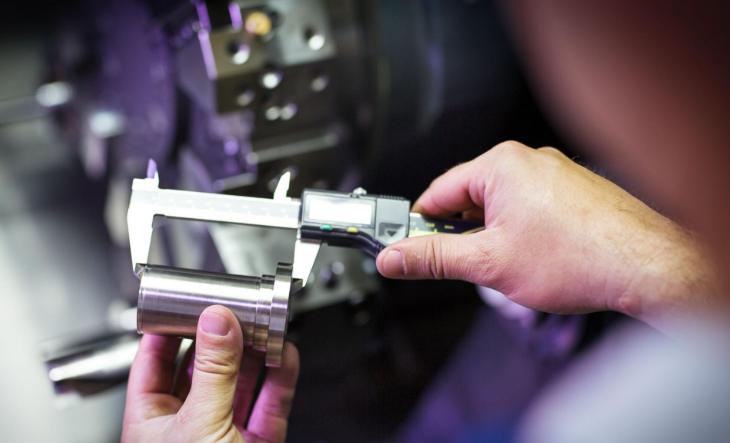
Calibration and Quality Verification
Assembly completion marks the beginning, not the end, of quality assurance. Every CNC cut the machine will ever make depends on calibration performed before shipment.
Modern CNC machine manufacturers implement multi-stage verification protocols. According to Renishaw's documentation, quality control testing includes machine casting inspections, software debugging, geometric accuracy tests, positioning accuracy tests, cutting trials, and running tests. All test data is fully documented to demonstrate readiness for customer acceptance.
Geometric verification confirms that axes move truly perpendicular and parallel as designed. Laser interferometer systems like the Renishaw XL-80 measure positioning accuracy across full axis travels, detecting errors as small as 0.0001mm. When errors are found, manufacturers can apply software compensation—but only if the underlying mechanical quality supports it.
The calibration and testing sequence includes:
- Geometric error mapping: Laser systems measure straightness, squareness, parallelism, and angular errors on all axes
- Positioning accuracy verification: Interferometer readings across full travel confirm positioning repeatability
- Thermal compensation calibration: Machines run through warm-up cycles while sensors track dimensional changes
- Test cutting: Sample parts are machined and measured to verify real-world performance
- Documentation: All calibration data is recorded, creating a baseline for future maintenance reference
According to MSP's accuracy verification guidance, comprehensive machine checking reveals whether errors are kinematic (correctable through software) or mechanical (requiring physical intervention). This distinction is critical—software compensation can mask mechanical problems but cannot eliminate them.
What separates exceptional CNC machine manufacturers from average ones often comes down to this final stage. Some manufacturers rush calibration to meet delivery deadlines. Others—those building machines for demanding industries—invest hours in verification and fine-tuning. The difference shows up in every part the machine produces for years afterward.
Test cuts verify that theoretical calibration translates to real-world performance. Machinists run sample parts, measuring features against specifications. If results fall outside tolerance, engineers trace problems back through the assembly process, making corrections until performance meets standards.
This rigorous approach to building CNC machines explains why quality equipment commands premium prices—and why cutting corners during manufacturing creates machines that disappoint. Understanding the manufacturing process also reveals why ongoing maintenance becomes essential for preserving the precision built into every machine at the factory.
Maintenance and Lifecycle Management for CNC Equipment
You've seen how CNC machines are engineered and assembled with micron-level precision. But here's the reality that many manufacturers learn the hard way: all that careful calibration means nothing if maintenance falls by the wayside. A machine that held ±0.005mm tolerances at installation can drift into scrap-producing territory within months without proper care.
According to research from Aberdeen, 82% of companies have experienced unplanned downtime over the past three years. For CNC machining equipment specifically, these unexpected breakdowns create a domino effect—missed deadlines, scrapped parts, and repair costs that dwarf what preventive maintenance would have required.
Whether you're running a single CNC machine used for prototyping or managing dozens of cnc machining centers across multiple production lines, understanding maintenance requirements determines whether your equipment delivers decades of reliable service or becomes a constant source of frustration.
Preventive Maintenance Protocols
Think of preventive maintenance as an investment rather than an expense. According to research from Deloitte, manufacturers implementing preventive maintenance programs typically see 25-30% fewer equipment failures, 70% reduction in emergency repairs, and up to 35% lower maintenance costs over time.
Daily maintenance forms the foundation of machine working reliability. These quick checks take 10-15 minutes per machine but catch most problems before they escalate:
- Lubrication verification: Confirm automatic lubrication systems have adequate oil; check indicator lights showing last lubrication cycle
- Coolant inspection: Verify levels, check concentration with a refractometer, and look for contamination or unusual odor indicating bacterial growth
- Hydraulic system check: Inspect oil levels against sight glass; low hydraulic fluid causes weak clamping that compromises safety and accuracy
- Safety systems test: Verify all emergency stops function correctly; test limit switches preventing over-travel
- Visual inspection: Clean chips from the machine bed, inspect way covers for damage, and check spindle area for buildup
Weekly maintenance digs deeper into industrial machining equipment condition. Air filters need attention—especially in dusty environments. Coolant nozzles can clog with chips, reducing cooling effectiveness. Ball screws and linear ways require inspection for signs of wear, contamination, or insufficient lubrication.
Monthly and quarterly tasks address components that don't need constant attention but are too critical to neglect:
- Coolant concentration testing: Use a refractometer to verify 5-10% concentration; pH should remain between 8.5-9.5
- Filter replacement: Replace air, hydraulic, and coolant filters according to usage intensity
- Belt inspection: Check drive belts for proper tension, alignment, cracking, or glazing
- Backlash testing: Use machine diagnostics or MDI to verify axis positioning accuracy
- Spindle runout check: Dial indicator readings exceeding 0.0002" indicate bearing wear requiring attention
Wear Patterns and Component Replacement
Every type of machine experiences predictable wear patterns. Understanding these helps you anticipate maintenance needs rather than reacting to failures.
Coolant-related problems rank among the most common issues. Bacterial growth leads to foul odors, reduced performance, and potential health concerns. According to Blaser Swisslube's coolant management guide, maintaining proper concentration and pH can extend coolant life by 3-4 times compared to poorly managed systems.
Ball screws and linear guides experience gradual wear that manifests as increasing backlash. When positioning errors creep upward despite software compensation, replacement becomes necessary. Spindle bearings represent another high-value wear item—early detection through vibration monitoring or temperature tracking prevents catastrophic failures that damage spindles beyond repair.
When should you service versus replace components? Consider these guidelines:
- Service when: Problems are caught early; wear is within adjustable limits; component costs exceed repair costs by less than 3x
- Replace when: Wear exceeds adjustment capability; repeated repairs indicate systemic failure; downtime costs from unreliability exceed replacement costs
- Annual considerations: Hydraulic oil changes, spindle bearing inspections, ballscrew and guide wear measurements, and complete machine calibration against baseline specifications
For annual maintenance, many operations bring in the manufacturer's service technician. These specialists have diagnostic tools, detailed service manuals, and access to performance data from similar machines. While this service carries costs, it's typically far less expensive than downtime from undiagnosed problems developing into major failures.
Maximizing Machine Uptime and Accuracy
The most successful operations view maintenance strategically. According to industry research, unplanned downtime can cost manufacturers anywhere from $10,000 to $250,000 per hour depending on the industry. For CNC equipment, even a few hours of unexpected breakdown represents thousands in lost revenue.
Modern computerized maintenance management systems (CMMS) transform how facilities handle maintenance. These platforms automatically generate preventive maintenance work orders based on calendar time, operating hours, or custom triggers. Technicians receive mobile notifications, complete tasks, and document results without touching paper.
Key operational practices that maximize equipment longevity include:
- Warm-up procedures: Run spindles and axes through warm-up cycles before precision work; thermal stability directly affects accuracy
- Environmental control: Maintain consistent shop temperature; machines calibrated at 20°C drift as ambient conditions change
- Operator training: Experienced operators notice when machine sounds change or behavior shifts; document this knowledge for team sharing
- Data tracking: Monitor calibration trends over time; increasing corrections indicate wear requiring attention
- Spare parts inventory: Stock critical components like filters, belts, and common wear items to minimize downtime waiting for parts
CNC machines typically provide reliable service for 15-20 years with proper maintenance. Annual reviews help identify when machines approach the end of their useful life—comparing repair costs, downtime frequency, and capability limitations against replacement investments.
The bottom line? You're either paying for maintenance on your schedule or paying much more for repairs on the machine's schedule. Organizations that implement systematic preventive maintenance programs, supported by proper documentation and trained personnel, consistently outperform those relying on reactive approaches. And as these machines increasingly connect to factory networks and cloud systems, maintenance itself is evolving—which brings us to smart manufacturing and Industry 4.0 integration.
Smart Manufacturing and Industry 4.0 Integration
Maintenance programs keep machines running—but what if your equipment could tell you when problems are developing before they cause downtime? What if you could test new CNC programs without risking crashes on actual machines? This is exactly what Industry 4.0 technologies now enable.
According to Visual Components, Industry 4.0 refers to the emergence of cyber-physical systems that create a step-change in manufacturing capabilities—comparable to earlier revolutions brought by steam, electricity, and computerization. In practical terms, this means combining advanced sensor technologies with internet connectivity and artificial intelligence to create smart manufacturing systems.
For CNC machine manufacturing, these technologies transform how equipment operates, how maintenance happens, and how new machines are commissioned. Understanding what is CNC programming in this connected environment means recognizing that code doesn't just control cutting anymore—it generates data that drives continuous improvement.
Connected Machines and Real-Time Monitoring
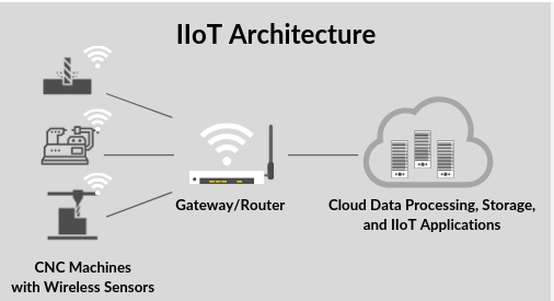
Imagine walking onto a factory floor where every computer numerically controlled machine reports its status in real time. Spindle loads, axis positions, coolant temperatures, and vibration signatures stream continuously to central monitoring systems. This isn't futuristic—it's happening now in advanced manufacturing facilities worldwide.
IoT (Internet of Things) integration enables CNC equipment to communicate with factory networks, cloud platforms, and enterprise systems. Sensors embedded throughout machines capture data that was previously invisible to operators and managers.
Key Industry 4.0 features transforming CNC machine manufacturing include:
- Real-time status monitoring: Dashboard displays show machine utilization, cycle times, and production counts across entire facilities
- Automated alerts: Systems notify maintenance teams when parameters drift outside normal ranges—before problems affect parts
- Energy monitoring: Power consumption tracking identifies inefficiencies and supports sustainability initiatives
- OEE calculation: Overall Equipment Effectiveness metrics are calculated automatically from machine data rather than manual logs
- Remote diagnostics: Machine builders can troubleshoot problems from anywhere, often resolving issues without on-site visits
For a cnc machining business, this connectivity delivers tangible benefits. Production managers see instantly which machines are running, which are idle, and which need attention. Scheduling becomes more accurate when actual cycle times replace estimates. Quality teams trace problems back to specific machines, tools, and operating conditions.
Modern CNC machine manufacturers increasingly build connectivity into their equipment from the design stage. Controllers from Fanuc, Siemens, and others include standardized communication protocols like MTConnect and OPC-UA that simplify integration with factory systems. What once required custom programming now works through configuration.
Predictive Analytics and Smart Maintenance
Remember that 82% of companies experiencing unplanned downtime we mentioned earlier? Predictive analytics aims to eliminate those surprises entirely. Instead of waiting for failures or replacing components on fixed schedules regardless of actual condition, smart systems analyze data patterns to predict when maintenance will actually be needed.
Here's how it works in practice. Vibration sensors on spindle bearings continuously capture frequency signatures. Machine learning algorithms learn what normal operation looks like for each specific machine. When subtle changes appear—perhaps increased vibration at certain RPMs—the system flags developing problems weeks before catastrophic failure would occur.
Computer numerical control programming now extends beyond toolpaths to include condition monitoring parameters. A computer numerically controlled cnc machinist working with modern equipment monitors not just part quality but machine health indicators that predict future performance.
Benefits of predictive maintenance for CNC operations include:
- Reduced unplanned downtime: Problems are addressed during scheduled maintenance windows rather than causing emergency stoppages
- Optimized parts inventory: Replacement components are ordered when actually needed rather than stockpiled "just in case"
- Extended component life: Parts run until they actually need replacement rather than being discarded based on conservative time-based schedules
- Lower maintenance costs: Resources focus on equipment that needs attention rather than unnecessary preventive work
- Improved safety: Developing failures are caught before they create hazardous conditions
The cncs program that drives a modern machine generates gigabytes of data daily. Sophisticated analytics platforms process this information, correlating cutting parameters with tool wear, environmental conditions with dimensional accuracy, and maintenance history with failure patterns. Each production cycle makes the predictive models smarter.
Digital Twins and Virtual Commissioning
Perhaps no Industry 4.0 concept captures imagination quite like digital twins. According to Visual Components, a digital twin is a virtual recreation of a physical system—a computer model that looks, acts, and behaves just like the physical system it replicates. Furthermore, connections between the two enable data exchange so the virtual system can synchronize with the real system.
A digital twin is far more than a CAD model. It includes multi-physics simulation that replicates speeds, loads, temperatures, pressures, inertia, and external forces. For CNC equipment, this means testing programs virtually before risking actual machines and workpieces.
Virtual commissioning takes this concept specifically into machine building. As Visual Components explains, it involves simulating control logic and signals that will enable automation to work—completing system controls validation before physical systems exist. For CNC machine manufacturers, this dramatically shortens project timelines.
Key applications of digital twins in CNC manufacturing include:
- Program verification: Test toolpaths in virtual environments, catching collisions and inefficiencies before any metal is cut
- Operator training: Train personnel on virtual machines without tying up production equipment or risking crashes
- Process optimization: Experiment with cutting parameters, tooling changes, and fixture modifications in simulation
- Predictive modeling: Combine real-time machine data with simulation to predict how changes will affect outcomes
- Remote collaboration: Engineers worldwide can analyze the same virtual machine simultaneously
The benefits extend throughout equipment lifecycle. According to industry research, virtual commissioning can begin while physical construction is underway—making commissioning a parallel rather than sequential activity. Problems in system logic or timing are discovered earlier. Changes can often be made quickly with minimal impact on project duration.
For organizations evaluating CNC machine manufacturers, asking about digital twin capabilities reveals technological sophistication. Manufacturers offering virtual commissioning can demonstrate machine behavior before physical delivery. Training can begin before equipment arrives. Integration issues are identified and resolved in simulation rather than on the production floor.
These smart manufacturing technologies aren't just nice-to-have features—they're becoming competitive necessities. Operations running Industry 4.0-enabled equipment gain visibility, reduce costs, and respond faster to problems than those relying on traditional approaches. As you evaluate CNC machines and manufacturers, understanding these capabilities helps you assess which partners are positioned for the future of manufacturing.
Evaluating CNC Machines and Selecting Manufacturers
You've explored how CNC machines work, how they're built, and how smart manufacturing transforms operations. Now comes the critical question many buyers struggle with: how do you actually evaluate CNC machines and choose the right manufacturer? Lists of top rated cnc machines are everywhere—but without evaluation criteria, those rankings mean little for your specific needs.
The difference between the best cnc machines for your application and an expensive disappointment often comes down to asking the right questions. Price matters, certainly. But focusing only on purchase price ignores factors that determine whether equipment delivers value for years—or headaches within months.
Precision and Repeatability Standards
When manufacturers quote accuracy specifications, are they comparing apples to apples? Not always. Understanding how precision is measured helps you cut through marketing claims to find equipment that genuinely meets your requirements.
Positioning accuracy describes how close the machine moves to commanded positions. A specification of ±0.005mm means the axis should land within 5 microns of where the program tells it to go. But this single number doesn't tell the whole story.
Repeatability measures consistency—how closely the machine returns to the same position over multiple attempts. For production work, repeatability often matters more than absolute accuracy. A machine that consistently lands 0.003mm off-target can be compensated; one that varies unpredictably cannot.
When evaluating the best cnc milling machine options for precision work, look for these specifications:
- ISO 230-2 compliance: This standard defines how positioning accuracy and repeatability should be measured—ensuring comparable specifications between manufacturers
- Volumetric accuracy: How the machine performs across its entire working envelope, not just along individual axes
- Thermal stability: How accuracy changes as the machine warms up during operation
- Geometric accuracy: Squareness, parallelism, and straightness of axis movements
Request actual calibration reports—not just catalog specifications. Reputable manufacturers provide laser interferometer data showing measured performance on each machine. If a vendor can't produce this documentation, consider it a warning sign.
Build Quality and Rigidity Assessment
Specifications on paper mean nothing if mechanical quality doesn't support them. The best cnc mill maintains accuracy under cutting loads that would cause lesser machines to deflect and chatter.
Rigidity starts with the machine base. As we discussed earlier, quality castings from controlled iron compositions outperform those made from recycled scrap. But how can buyers assess this without metallurgical testing?
Look for these build quality indicators:
- Base construction: Ask about casting source, material grade, and stress-relieving processes; reputable manufacturers document their foundry partnerships
- Guideway type: Box ways provide maximum rigidity for heavy cutting; linear guides offer speed advantages for lighter work
- Spindle bearing configuration: Angular contact bearings in matched sets indicate quality; ask about preload methods and thermal management
- Component sourcing: Premium machines use Japanese or German ball screws, linear guides, and controllers; vague answers about component origins suggest cost-cutting
Physical inspection reveals what specifications cannot. When evaluating best cnc machines in person, push firmly on the spindle head and table. Quality machines feel solid and immovable. Budget equipment may flex noticeably—a sign of inadequate rigidity that will show up in part quality.
Service Networks and Long-Term Support
A machine that runs flawlessly needs occasional maintenance. One that develops problems needs responsive support. Before purchasing, investigate what happens after the sale.
According to Shibaura Machine's TCO analysis, true total cost of ownership extends far beyond purchase price. After-purchase costs include operator and maintenance staff training, perishable tooling, utilities, depreciation, and ongoing machine maintenance. Manufacturers report that maintenance costs vary significantly based on machine build quality.
Key service considerations include:
- Geographic coverage: How far is the nearest service technician? Response time matters when production is down
- Parts availability: Are common wear items stocked locally, or do they ship from overseas?
- Training programs: Does the manufacturer offer operator and maintenance training? What does it cost?
- Remote diagnostics: Can technicians troubleshoot problems remotely before dispatching service calls?
- Warranty terms: What's covered, for how long, and what voids coverage?
Talk to existing customers—not references provided by the manufacturer, but shops you find independently. Ask about service response times, parts costs, and whether they'd buy from the same cnc machine brands again.
| Evaluation Criteria | What to Look For | Why It Matters |
|---|---|---|
| Positioning Accuracy | ISO 230-2 certified measurements; actual calibration reports | Determines whether the machine can produce parts to your tolerance requirements |
| Repeatability | Specifications under ±0.003mm for precision work; consistency across temperature changes | Production parts must be consistent; poor repeatability means scrap and rework |
| Spindle Quality | Runout under 0.002mm; documented bearing configuration; thermal compensation | Surface finish and tool life depend on spindle precision and stability |
| Controller Capability | Major brands (Fanuc, Siemens, Heidenhain); look-ahead processing; connectivity options | Programming flexibility, feature availability, and long-term support depend on controller choice |
| Structural Rigidity | Documented casting quality; appropriate guideway type for application; solid feel when pushed | Rigidity determines cutting performance, accuracy under load, and long-term stability |
| Service Support | Local technicians; stocked parts; reasonable response time commitments | Downtime costs far exceed service contract costs; poor support multiplies problems |
| Total Cost of Ownership | Energy consumption; maintenance requirements; expected consumable costs; resale value | Purchase price represents only 20-40% of lifetime equipment cost |
Before finalizing any purchase, request test cuts on actual machines. Provide your own material and part design—not a demonstration piece the manufacturer has optimized. Measure results with your own inspection equipment. A vendor confident in their equipment welcomes this scrutiny; one who resists may be hiding capability limitations.
Verification procedures should include running the machine through warm-up cycles, then cutting test parts at the beginning and end of a shift. Compare dimensional results to verify thermal stability. Check surface finishes against your quality requirements. If possible, observe the machine running unattended to assess reliability in automated operation.
Choosing among cnc brands ultimately requires balancing capability against budget, service against features, and present needs against future growth. The evaluation framework above gives you the tools to make that decision based on evidence rather than marketing claims. With clear criteria in hand, you're prepared to assess not just individual machines but the manufacturers behind them—and to consider the strategic factors that determine long-term partnership success.
Strategic Considerations for CNC Manufacturing Partnerships
You now have the technical knowledge to evaluate individual machines and manufacturers. But here's the bigger picture question: how do you build lasting partnerships with cnc manufacturing companies that will support your production needs for years to come? The answer goes beyond equipment specifications to encompass quality systems, operational flexibility, and strategic alignment.
Whether you're sourcing precision components from cnc manufacturing shops or considering major equipment acquisitions, understanding what separates reliable partners from problematic suppliers prevents costly mistakes. The evaluation criteria we covered provide a starting point—but strategic partnerships require examining certifications, scalability, and long-term support capabilities that determine whether a relationship thrives or struggles.
Quality Certifications and Industry Standards
When evaluating cnc machine companies for automotive, aerospace, or medical applications, certifications aren't just nice credentials—they're often mandatory requirements. More importantly, the rigor required to achieve and maintain these standards reveals how seriously a manufacturer approaches quality.
IATF 16949 represents the gold standard for automotive supply chain quality management. This certification—developed by the International Automotive Task Force—goes far beyond basic ISO 9001 requirements. It demands documented processes for defect prevention, reduction of variation in the supply chain, and continuous improvement methodologies.
Why does this matter for your procurement decisions? A cnc machining co holding IATF 16949 certification has demonstrated:
- Process control rigor: Every manufacturing step follows documented procedures with defined quality checkpoints
- Traceability systems: Parts can be traced back to specific machines, operators, material lots, and process parameters
- Corrective action protocols: When problems occur, root cause analysis prevents recurrence rather than just addressing symptoms
- Supplier management: Sub-tier suppliers are evaluated and monitored to maintain quality throughout the supply chain
- Customer-specific requirements: Systems accommodate unique specifications from different OEMs
Statistical Process Control (SPC) capabilities transform quality from inspection-based to prevention-based. Rather than checking parts after machining and sorting out defects, SPC monitors processes in real time—catching drift before it produces out-of-tolerance parts.
For example, Shaoyi Metal Technology combines IATF 16949 certification with strict SPC implementation for their automotive CNC machining services. This dual approach ensures high-tolerance components meet specifications consistently—not just during initial qualification runs but throughout production campaigns.
Other certifications to consider based on industry requirements include:
- AS9100: Aerospace quality management standard with enhanced requirements for risk management and configuration control
- ISO 13485: Medical device quality management with emphasis on regulatory compliance and product safety
- NADCAP: Special process accreditation for heat treating, non-destructive testing, and other critical operations
Scaling from Prototype to Production
Imagine finding the perfect cnc co for your prototype development—only to discover they can't scale when your product succeeds. Or conversely, partnering with high-volume cnc machine producers who can't be bothered with small prototype runs. The most valuable manufacturing relationships offer flexibility across the entire product lifecycle.
What does scalability actually look like in practice? Consider these capability indicators:
- Equipment diversity: Shops with both Swiss-type lathes for precision components and larger machining centers for structural parts can handle varied requirements
- Capacity headroom: Partners running at 100% utilization can't absorb your growth; look for 70-80% utilization with room to expand
- Process documentation: Detailed process sheets and programs developed during prototyping transfer seamlessly to production runs
- Quality system scalability: SPC sampling strategies that work for 100 pieces must adjust appropriately for 100,000 pieces
Lead time capabilities often separate adequate suppliers from exceptional partners. When market opportunities emerge, waiting weeks for prototype iterations costs competitive advantage. The best cnc manufacturing companies offer rapid prototyping with turnaround times measured in days rather than weeks—some achieving lead times as fast as one working day for urgent requirements.
Shaoyi Metal Technology exemplifies this scalability approach, offering seamless transitions from rapid prototyping to mass production. Their facility handles everything from complex chassis assemblies to custom metal bushings, with lead times designed around customer urgency rather than internal convenience.
"The true test of a manufacturing partnership isn't how well things go when everything runs smoothly—it's how quickly and effectively your partner responds when challenges arise."
Partnering for Precision Manufacturing Success
Strategic partnerships extend beyond transactional vendor relationships. The most successful manufacturing collaborations involve shared problem-solving, transparent communication, and mutual investment in long-term success.
When evaluating potential cnc machine producers as partners, consider these strategic factors:
- Technical collaboration: Does the manufacturer offer Design for Manufacturability (DFM) feedback? Partners who improve your designs create more value than those who simply quote what you send
- Communication practices: How quickly do they respond to inquiries? Are project updates proactive or only when you ask? Responsiveness during quoting predicts responsiveness during production
- Problem resolution: Ask about recent quality escapes and how they were handled; transparent discussion of problems and solutions indicates maturity
- Investment trajectory: Is the company reinvesting in new equipment, training, and capabilities? Stagnant operations eventually fall behind
- Cultural alignment: Do their priorities match yours? A partner focused on premium quality frustrates customers chasing lowest price, and vice versa
Geographic considerations also matter for strategic partnerships. While global sourcing offers cost advantages, consider supply chain resilience, shipping times, communication barriers, and intellectual property protections. The lowest piece-price means little if logistics delays halt your production line.
For automotive applications specifically, working with certified specialists like Shaoyi Metal Technology provides advantages that general-purpose shops cannot match. Their combination of automotive-focused CNC machining capabilities, IATF 16949 certification, and SPC-driven quality systems addresses the demanding requirements that automotive OEMs and Tier 1 suppliers face.
Building successful partnerships with cnc manufacturing companies requires looking beyond immediate project needs to long-term alignment. The evaluation frameworks we've covered throughout this article—from understanding machine components to assessing build quality to verifying Industry 4.0 capabilities—all feed into partnership decisions. Equipment matters, certifications matter, scalability matters. But ultimately, partnerships succeed when both organizations commit to shared success in precision manufacturing.
Frequently Asked Questions About CNC Machine Manufacturing
1. What is a CNC machine in manufacturing?
A CNC machine (Computer Numerical Control machine) is automated equipment controlled by pre-programmed software that executes precise cutting, drilling, milling, and other machining tasks with minimal human intervention. CNC machine manufacturing specifically refers to the process of designing, engineering, and assembling these sophisticated machines themselves—from precision casting of iron bases to final calibration and quality testing—rather than simply using them for machining services.
2. What are the main types of CNC machines used in manufacturing?
The primary types include 3-axis vertical machining centers (VMCs) for flat parts and simple molds, horizontal machining centers (HMCs) for box-shaped components, CNC lathes and turning centers for cylindrical parts, Swiss-type lathes for small precision components, and 4-axis and 5-axis machines for complex geometries requiring multiple-angle access. Each type combines specific component configurations to address different manufacturing applications and precision requirements.
3. What components are critical for CNC machine precision?
Key precision components include ball screws that convert rotational to linear motion with positioning accuracies of ±0.004mm, linear guides supporting axis movement with micron-level straightness, servo motors with closed-loop feedback systems, CNC controllers processing millions of calculations per second, and spindles delivering cutting power with runout under 0.002mm. Premium Japanese and German components from manufacturers like THK, NSK, Fanuc, and Siemens typically indicate higher build quality.
4. How are CNC machines manufactured and calibrated?
CNC machine manufacturing begins with precision casting of machine bases using controlled iron compositions and stress-relieving heat treatments. Assembly follows careful sequences with laser alignment systems ensuring micron-level geometric accuracy. Final calibration involves laser interferometer measurements of positioning accuracy, geometric error mapping, thermal compensation calibration, and test cutting verification. This rigorous process determines whether machines maintain tolerances for decades of production use.
5. What certifications should I look for when selecting CNC manufacturing partners?
For automotive applications, IATF 16949 certification demonstrates rigorous quality management including process control, traceability systems, and corrective action protocols. Statistical Process Control (SPC) capabilities indicate prevention-based quality approaches. Aerospace suppliers should hold AS9100 certification, while medical device manufacturers need ISO 13485 compliance. Partners like Shaoyi Metal Technology combine IATF 16949 certification with SPC implementation for consistent high-tolerance automotive component production.