 Small batches, high standards. Our rapid prototyping service makes validation faster and easier —

Cnc Lathe Machining Decoded: Components, Costs & Partner Selection
What CNC Lathe Machining Actually Means
Ever wondered what makes modern manufacturing so incredibly precise? The answer often lies in CNC lathe machining—a process that transforms raw materials into flawless cylindrical components with remarkable accuracy.
A CNC lathe machine is an automated machine tool that rotates a workpiece on a spindle while computer-controlled cutting tools shape it into precise cylindrical or conical forms, achieving tolerances as tight as one-thousandth of an inch.
So, what is a CNC lathe exactly? It's a computer numerical control lathe that replaces manual adjustments with programmable instructions. Instead of relying on an operator's steady hand and years of training, the machine interprets digital commands to control cutting speed, tool position, and depth with extraordinary consistency. This technology matters deeply to engineers sourcing precision components, procurement specialists evaluating suppliers, and manufacturing decision-makers seeking competitive advantages in quality and throughput.
The Core Principle Behind Rotational Precision
To define lathe in its simplest terms, imagine a pottery wheel—but engineered for metal, plastic, or composite materials. The definition of lathe centers on rotation: the workpiece spins while a stationary or moving cutting tool removes material layer by layer.
What does a lathe do in practical manufacturing? It creates parts with rotational symmetry—think shafts, bushings, fasteners, and pipe fittings. The lathe meaning extends beyond simple turning; these machines can drill, bore, thread, and face surfaces with a single setup. According to Fictiv's machining analysis, CNC lathes can deliver tolerances to a thousandth of an inch in minutes, while manual methods require hours of setup and measurement.
From Manual Craft to Digital Control
The transition from manual to CNC operation represents more than technological advancement—it's a fundamental shift in manufacturing capability. Manual lathes demand highly skilled operators with years of training who must constantly calculate, measure, and adjust. A CNC lathe machine eliminates this variability by executing programmed sequences with perfect repeatability.
Here's what this digital control actually delivers:
- Real-time feedback: The computer interprets cutting resistance and automatically adjusts parameters
- Multi-axis coordination: Simultaneous movements that human operators simply cannot replicate
- Consistent quality: Every part matches the previous one, enabling true interchangeability in assemblies
Research indicates that machines retrofitted with CNC technology produce parts 75-300% faster than their manual counterparts. What does lathe do when computer-controlled? It transforms from a skilled craft into a scalable, repeatable manufacturing process—one where precision doesn't depend on who's operating the machine, but on the quality of programming and equipment.
Essential Components That Drive Precision
Understanding what a CNC lathe can accomplish starts with knowing what's inside it. Picture a symphony orchestra—each instrument plays a distinct role, yet the magic happens when they perform together. The parts of a CNC lathe work the same way. Every component influences machining capability, from the raw power delivered to the workpiece to the microscopic precision of each cut.
When you examine a lathe diagram, you'll notice these machines aren't simple tools. They're integrated systems where the quality of each element directly impacts your final part. Let's break down the CNC lathe components that matter most.
- Headstock and Spindle: Houses the main drive motor and spindle, delivering rotational power to spin the workpiece at controlled speeds
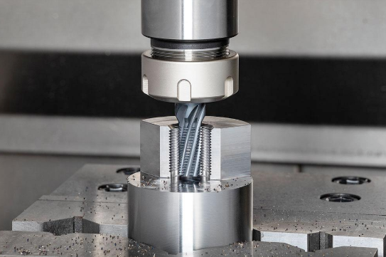
- Chuck: Grips the workpiece securely, ensuring concentricity and preventing slippage during cutting operations
- Tailstock: Provides end support for long or slender parts, preventing deflection and vibration
- Carriage and Cross-slide: Positions the cutting tools along the CNC lathe axis paths (X and Z) with servo-driven precision
- Tool Turret: Holds multiple cutting tools and indexes them automatically for multi-operation efficiency
- CNC Controller: The brain that interprets G-code programs and coordinates all machine movements
- Machine Bed: The foundation providing rigidity and vibration absorption—typically cast iron for thermal stability
The Spindle System and Rotational Power
Think of the headstock as your lathe's powerhouse. Located on the left side of the machine, it contains the spindle, drive motor, and gear system. According to Mekalite's comprehensive guide, the quality of the headstock directly affects both power delivery and rotational accuracy.
What makes the spindle so critical? It's the rotating shaft that transfers motor power to your workpiece. Key specifications include maximum RPM (revolutions per minute) and bore diameter—the hole through its center that determines the largest bar stock you can feed through. Higher spindle speeds enable faster material removal on softer materials like aluminum, while robust torque handles demanding cuts in steel and titanium.
The chuck mounts directly onto the spindle face. This is where precision begins. A 3-jaw self-centering chuck automatically centers round stock, making it ideal for production work. Need to grip irregular shapes? A 4-jaw independent chuck lets you adjust each jaw separately. For maximum accuracy in high-volume runs, collet chucks provide the tightest grip with minimal runout.
On the opposite end, the tailstock slides along the bed's guideways. When you're machining a long shaft, the cutting forces can cause the free end to flex. The tailstock's quill—a hollow shaft with a center point—engages the workpiece end, counteracting those forces. This support is essential for achieving tight tolerances and smooth surface finishes on slender parts.
How the Turret Enables Multi-Operation Efficiency
Here's where CNC technology truly shines. The CNC lathe turret is an indexable disc or block holding 8, 12, or even 16 tool stations. When your program calls for a different operation—say, switching from rough turning to threading—the turret rotates automatically, bringing the correct tool into cutting position in seconds.
Imagine the carriage lathe setup of earlier decades: an operator manually changing tools, repositioning, and recalibrating for each operation. Today's turret systems eliminate that downtime entirely. As noted by Force One's component guide, modern CNC lathes can include live tooling on the turret, enabling milling and drilling operations while the part remains clamped—no secondary machine required.
The carriage and cross-slide move the turret along the machine's axes. In a standard 2-axis configuration, the Z-axis runs parallel to the spindle (left-right movement), while the X-axis moves perpendicular (in-out movement). These lathe cnc parts travel on hardened, precision-ground guideways, driven by servo motors and ball screws that convert rotation into exact linear positioning.
Orchestrating all this motion is the CNC controller—the brain interpreting every programmed command. Popular controller brands like Fanuc, Siemens, and Haas provide the human-machine interface where operators load programs, monitor status, and make real-time adjustments. The controller's quality determines how precisely and quickly the machine can execute complex tool paths.
| Component | Manual Lathe | CNC Lathe |
|---|---|---|
| Tool Positioning | Hand wheels and manual measurement | Servo motors with sub-micron feedback |
| Tool Changes | Manual removal and installation | Automated turret indexing in seconds |
| Spindle Speed Control | Gear selection or belt adjustment | Variable frequency drive with programmed RPM |
| Operation Sequencing | Operator skill and memory | G-code program with perfect repeatability |
| Tailstock Movement | Manual positioning and locking | Programmable quill advance (on advanced models) |
| Coolant Application | Manual or simple on/off | Programmable flow targeting specific operations |
The parts of a cnc lathe represent decades of engineering refinement. Each component exists because precision manufacturing demands it. When you're evaluating machining partners or specifying equipment, understanding these fundamentals helps you ask better questions—and recognize quality answers. With the anatomy clear, the next logical step is exploring how different lathe types apply these components for specific manufacturing challenges.
CNC Lathe Types and When to Use Each
Now that you understand the components powering these machines, a bigger question emerges: which type of CNC lathe actually fits your project? Choosing the wrong configuration means wasted time, inflated costs, and parts that don't meet specifications. The right choice? It accelerates production, reduces setups, and delivers precision matched to your exact requirements.
Think of CNC lathe types like vehicles. A compact sedan handles city commutes efficiently, but you wouldn't haul construction materials with it. Similarly, a 2 axis cnc lathe excels at straightforward cylindrical parts, while a multi-axis machine tackles geometries that would otherwise require multiple operations. Let's decode which machine belongs in your manufacturing workflow.
Matching Axis Count to Part Complexity
The number of axes determines what movements the machine can execute—and ultimately, what shapes it can produce. A 2 axis lathe operates along the X-axis (perpendicular to the spindle) and Z-axis (parallel to the spindle). This configuration handles facing, straight turning, tapering, threading, and grooving with excellent efficiency.
When does a 2 axis lathe make sense? According to JSWAY's comparison analysis, these machines excel at producing cylindrical shapes like shafts, rods, and bushings. Their simplicity translates to reduced setup time, lower error rates, and more affordable costs. For small to medium production runs of straightforward parts, the 2 axis lathe delivers faster results due to streamlined operations.
But what happens when your part demands more? A 3 axis lathe adds a Y-axis—enabling off-center drilling, milling flats, and creating features that don't align with the spindle centerline. This capability eliminates secondary operations on separate milling machines, keeping parts clamped in a single setup for better accuracy.
Multi-axis configurations (4-axis and beyond) introduce rotational axes that unlock truly complex geometries. These machines can produce intricate components with exceptional precision in a single setup—reducing handling, improving concentricity, and minimizing cumulative tolerance errors. Industries like aerospace, automotive, medical, and defense rely heavily on multi-axis capabilities for parts that simply cannot be made efficiently on simpler equipment.
Here's the tradeoff: multi-axis lathes carry higher upfront costs and demand skilled programmers. As the reference materials note, the learning curve for effective multi-axis operation is steep, requiring comprehensive training. However, for production involving complex parts, the reduced cycle times and eliminated secondary setups often justify that investment.
When Swiss-Type Precision Makes the Difference
Swiss-type lathes occupy a specialized niche that conventional lathes cannot fill. Originally developed for watchmaking, these machines add a critical feature: a guide bushing that supports the workpiece extremely close to the cutting zone.
Why does this matter? When machining long, slender parts, cutting forces can cause deflection—the free end flexes away from the tool, destroying accuracy. According to Impro Precision's analysis, the Swiss lathe's guide bushing supports the workpiece right where the tool operates, dramatically reducing deflection. The result? Parts with length-to-width ratios of 20:1 and small diameters under 0.125 inches become practical—dimensions that would challenge conventional equipment.
Swiss lathes can operate with up to 13 axes and mount as many as 28 tools simultaneously. They perform turning, milling, drilling, boring, and knurling in a single process. Combined with automatic bar loaders, these machines enable lights-out production runs with minimal operator intervention.
Typical Swiss lathe applications include:
- Medical implants and surgical instruments requiring ultra-precision
- Miniature electronic connectors with intricate features
- Watch components and precision instrument parts
- Hydraulic valve components and aerospace fasteners
- Musical instrument posts and small shafts
The cnc auto lathe functionality of Swiss machines means consistent quality across thousands of parts. By using smaller bar stock, they also reduce material waste—a significant cost advantage for expensive alloys used in medical and aerospace applications.
Horizontal vs. Vertical Configuration Decisions
Beyond axis count and Swiss-type designs, the spindle orientation fundamentally shapes what a lathe handles best. A horizontal cnc lathe positions the spindle parallel to the floor, making it the default choice for most turning applications. According to Dongs Solution's configuration guide, horizontal lathes excel with long, cylindrical parts and handle heavier materials like high-strength plastics and aluminum efficiently.
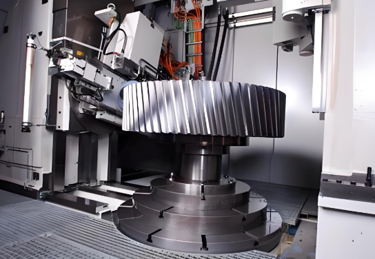
Vertical CNC lathes flip the orientation—the spindle points upward. This configuration shines for large, heavy workpieces where gravity assists loading and chip removal. Chips fall away naturally instead of accumulating in the cutting zone, reducing cleanup and improving surface finish. Operators also gain better visibility during machining, making setup verification easier.
Which configuration fits your operation? Consider these factors:
- Part geometry: Horizontal for long cylindrical parts; vertical for large-diameter, heavy workpieces
- Chip management: Vertical lathes offer easier, faster chip evacuation
- Floor space: Vertical machines often have smaller footprints for equivalent capacity
- Loading requirements: Gravity assists vertical loading of heavy parts; automation integrates more naturally with horizontal setups
| Lathe Type | Typical Applications | Part Size Range | Complexity Capability | Ideal Industries |
|---|---|---|---|---|
| 2-Axis Lathe | Shafts, rods, bushings, simple cylindrical parts | Small to medium diameter | Basic turning, threading, facing | General manufacturing, automotive components |
| 3-Axis Lathe | Parts with off-center features, flats, cross-holes | Small to medium diameter | Moderate—adds Y-axis milling capability | Industrial equipment, hydraulics |
| Multi-Axis (4+) | Complex geometries, contoured surfaces, multitasking | Varies by configuration | High—simultaneous multi-axis machining | Aerospace, defense, medical devices |
| Swiss-Type | Long/thin parts, miniature components, precision instruments | Small diameter (under 1.25 inches typical) | Very high—up to 13 axes, 28 tools | Medical, electronics, watchmaking |
| Horizontal CNC | Long cylindrical parts, bar work, production turning | Wide range—depends on swing | Varies by axis count | Automotive, general manufacturing |
| Vertical CNC | Large-diameter parts, heavy workpieces, disk-shaped components | Large diameter, shorter lengths | Varies by axis count | Energy, heavy equipment, oil and gas |
A cnc lathe and milling machine combination—often called a mill-turn or multitasking center—deserves mention here. These hybrid machines integrate turning with full milling capability on live tooling, producing complete parts in single setups. While the investment is substantial, the eliminated handling and improved accuracy make cnc lathe and milling configurations increasingly popular for complex, high-value components.
Selecting the right lathe type isn't about finding the most advanced machine—it's about matching capability to requirement. A simple 2 axis lathe producing thousands of identical bushings per week outperforms an underutilized multi-axis machine sitting idle between complex jobs. With lathe types clarified, the next consideration becomes understanding exactly what operations these machines perform and how each process contributes to your finished part.
Core Operations From Roughing to Finishing
Understanding lathe types only gets you halfway. The real question is: what exactly happens once the spindle starts spinning? CNC lathe turning transforms raw stock into finished components through a sequence of coordinated operations—each designed to remove material strategically while achieving specific dimensional and surface quality targets.
Think of lathe machining like sculpting. You start with rough cuts to establish basic shape, then progressively refine until the final form emerges. Every operation serves a purpose, and knowing when to apply each one separates efficient production from wasted time and scrapped parts.
Here's the typical progression from raw material to finished component:
- Facing: Establishes a flat, perpendicular reference surface at the workpiece end
- Rough Turning: Rapidly removes bulk material to approach final diameter
- Finish Turning: Achieves final dimensions with tight tolerances and smooth surfaces
- Grooving: Creates narrow channels for O-rings, snap rings, or clearance
- Threading: Cuts helical patterns for fastening applications
- Boring: Enlarges and refines internal hole diameters
- Drilling: Creates initial holes along the spindle axis
- Parting/Cutoff: Separates the finished part from bar stock
Turning Operations for External Profiles
Machining turning begins with external diameter reduction—the fundamental operation that defines cnc turning lathe capability. During turning, the cutting tool feeds along the rotating workpiece, shaving material to reduce diameter progressively.
Sounds simple? The complexity lies in parameter selection. According to TiRapid's turning operations guide, three core variables control every cut: spindle speed, feed rate, and depth of cut. These parameters interact constantly—change one, and you affect surface finish, tool life, and cycle time.
Here's how the relationship works:
- Spindle Speed (RPM): Higher speeds improve surface finish but generate more heat. Aluminum tolerates 3000+ RPM; titanium requires slower speeds around 150-300 RPM to prevent tool damage.
- Feed Rate (mm/rev): Determines how quickly the tool advances per spindle rotation. Roughing uses aggressive feeds (0.15-0.25 mm/rev) for material removal; finishing drops to 0.03-0.1 mm/rev for smooth surfaces.
- Depth of Cut: Controls how much material each pass removes radially. Roughing cuts may reach 2-3mm depth; finishing passes stay under 0.5mm to minimize deflection.
For cnc lathe turning of 304 stainless steel, industry data suggests cutting speeds of 80-120 m/min with feed rates controlled at 0.15-0.25 mm/rev to achieve surface roughness below Ra 1.6μm. Harder materials demand adjusted parameters—titanium alloys, for example, require reduced speeds and feeds between 0.05-0.1 mm/rev to prevent heat accumulation that destroys cutting edges.
Facing complements turning by machining the workpiece end perpendicular to the rotation axis. This operation establishes the length reference and creates a flat surface for subsequent operations or assembly. The cutting tool moves radially from the outer diameter toward center—or vice versa—producing a clean, square face. Achieving flatness within 0.01mm requires proper tool geometry and controlled feed rates, typically around 0.1 mm/rev for roughing, dropping to 0.03 mm/rev for finishing passes that reach Ra 0.8μm surface quality.
Long lathe turning presents additional challenges. When workpiece length exceeds three times the diameter, deflection becomes a real concern. The machining lathe must compensate through tailstock support, reduced depth of cut, and strategic toolpath planning that minimizes cutting forces on unsupported sections.
Internal Machining Through Boring and Threading
External profiles tell only half the story. Many components require precise internal features—and that's where boring, drilling, and threading operations become essential.
Drilling initiates internal features by creating holes along the spindle axis. The drill penetrates the rotating workpiece, removing material to establish an initial cavity. Practical experience indicates that center drill positioning combined with step drilling prevents wandering and ensures straight holes. Cutting speeds for drilling aluminum typically reach 100-120 m/min with feeds of 0.1-0.2 mm/rev, while intermittent chip evacuation prevents accumulation that could break tools or burn hole walls.
Boring refines what drilling starts. This operation uses a single-point boring bar to enlarge existing holes with precision that drilling alone cannot achieve. Unlike drilling's fixed tool diameter, boring allows incremental adjustments to hit exact dimensions. According to machining process data, boring achieves tolerances within ±0.01mm and surface roughness of Ra 0.4-0.8μm—critical for bearing seats, cylinder bores, and precision fits.
For deep holes exceeding a 5:1 length-to-diameter ratio, lathing machining requires stepped pre-boring strategies with internal coolant systems. Without proper chip evacuation and heat management, bore deflection accumulates and tolerances suffer.
Threading creates helical patterns for fastening—both external threads on shafts and internal threads in bores. CNC lathes execute threading through synchronized spindle rotation and tool feed, typically programmed using G76 or G32 codes. The process requires multiple passes: initial cuts at 0.2mm depth, decreasing approximately 20% per pass, with final cleaning passes ensuring thread flank accuracy.
Standard metric threading (M10×1.5, for example) demands constant spindle speeds of 500-800 RPM throughout the cutting cycle. Speed variations cause "random teeth" defects that ruin thread engagement. For internal threads or fine pitches, hardened inserts with TiAlN coatings extend tool life while maintaining ISO 6g or tighter tolerances.
Grooving cuts narrow channels into the workpiece—essential for O-ring seats, snap ring retention, or clearance for grinding wheels. Special grooving tools with widths from 1.0-3.0mm plunge radially into the material, creating precise channels. Cutting speeds for stainless steel and titanium remain moderate (80-120 m/min) with internal coolant preventing overheating. Deep grooves require multiple plunge steps to avoid lateral tool bending that distorts groove geometry.
Finally, parting (or cutoff) separates the finished component from bar stock. This operation carries inherent risk—improper execution can damage completed parts or break tools. Best practice involves reducing cutting speed to approximately 50% of normal turning speed and programming pause-plus-slow-retreat sequences at the cut completion. Advanced machines use sub-spindle clamping to achieve vibration-free separation with smooth cut surfaces requiring no secondary finishing.
Every lathing machining operation builds upon the previous one. Rushing through roughing creates problems that finishing cannot fix. Ignoring parameter relationships wastes tools and produces inconsistent parts. Mastering this sequence—understanding not just what each operation does but when and why to apply it—transforms CNC lathe capability from theoretical specification into practical manufacturing advantage. With operations understood, the next critical factor becomes material selection: how different metals and polymers respond to these cutting processes, and what adjustments ensure optimal results.
Material Selection and Machinability Factors
You've mastered the operations—now comes a question that determines success before the spindle ever turns: what material are you cutting? The wrong choice doesn't just slow production. It destroys tools, blows tolerances, and transforms profitable jobs into expensive lessons.
Material selection for metal lathe machining involves far more than matching alloy to application. Each material responds differently to cutting forces, generates unique chip formations, and demands specific tooling strategies. Understanding these behaviors separates shops that quote confidently from those that hope for the best.
When you're learning how to use a metal lathe effectively, material knowledge becomes your foundation. According to Hubs' material selection guide, the process follows three essential steps: define requirements (mechanical, thermal, cost), identify candidate materials meeting those needs, and select the optimal compromise between performance and budget.
| Material | Machinability Rating | Typical Applications | Special Considerations |
|---|---|---|---|
| Aluminum 6061 | Excellent | General components, prototypes, housings | Can be anodized; non-magnetic |
| Aluminum 7075 | Very Good | Aerospace structures, high-stress components | Heat treatable to steel-like hardness |
| Stainless Steel 304 | Moderate | Medical, food processing, chemical equipment | Work hardens rapidly; requires sharp tools |
| Stainless Steel 303 | Good | High-volume fasteners, aerospace hardware | Added sulfur improves cutting; lower corrosion resistance |
| Mild Steel 1018 | Good | Fixtures, jigs, general-purpose components | Susceptible to corrosion; excellent weldability |
| Alloy Steel 4140 | Moderate | Shafts, gears, high-strength industrial parts | Heat treatable; not recommended for welding |
| Brass C36000 | Excellent | Connectors, fittings, decorative components | Free-machining; produces excellent surface finish |
| Titanium Grade 5 | Difficult | Aerospace, medical implants, marine components | Requires specialized tooling; low thermal conductivity |
| POM (Delrin) | Excellent | Gears, bearings, precision plastic parts | Low friction; excellent dimensional stability |
| PEEK | Good | Medical devices, aerospace, high-temp applications | Can replace metals; biocompatible grades available |
Aluminum and Brass for High-Speed Production
When speed and efficiency matter most, aluminum alloys deliver. A metal lathe machine running aluminum can operate at spindle speeds exceeding 3000 RPM—sometimes reaching 10,000+ RPM on high-speed equipment. Why so fast? Aluminum's low hardness and excellent thermal conductivity allow aggressive material removal without destroying cutting edges.
According to Xometry's materials analysis, Aluminum 6061 represents the most common general-purpose alloy, offering excellent mechanical properties combined with outstanding machinability. It welds easily, accepts anodizing for surface hardening, and machines to tight tolerances without fighting the operator.
Need higher strength? Aluminum 7075 adds zinc and magnesium for fatigue resistance approaching some steels—while maintaining the machinability advantages of the aluminum family. This alloy dominates aerospace applications where weight reduction is critical. The tradeoff? Higher material cost and slightly more demanding cutting parameters.
For applications requiring corrosion resistance in marine environments, Aluminum 5083 provides exceptional seawater resistance while remaining highly machinable. Steel lathe machines configured for aluminum should use sharp, polished carbide inserts with positive rake angles that shear material cleanly rather than pushing it.
Brass occupies a special position among lathes metal options. Brass C36000 (free-cutting brass) ranks among the most machinable materials available. Its unique chip-breaking characteristics produce short, easily evacuated chips instead of stringy tangles that wrap around tooling. Surface finishes achieve mirror-quality results directly from the machine—often eliminating secondary polishing operations.
What makes brass so cooperative? The addition of lead creates microscopic discontinuities that break chips naturally. Combined with brass's natural corrosion resistance and attractive gold color, these properties make it ideal for decorative hardware, electrical connectors, and plumbing fittings where appearance matters alongside function.
Challenging Materials That Demand Expertise
Not every material cooperates with cutting tools. Stainless steels, titanium alloys, and certain engineering plastics require adjusted strategies—and understanding these challenges prevents costly mistakes.
Stainless steel presents a paradox: it's everywhere in manufacturing, yet it punishes careless machining. The culprit? Work hardening. As you cut 304 stainless, the surface layer hardens under deformation. Dwell too long without cutting, or use dull tools that rub instead of shear, and you create a hardened skin that destroys subsequent passes.
The solution involves maintaining constant chip load, using sharp tools with positive geometry, and never allowing the tool to ride without cutting. According to machining reference data, Stainless Steel 303 offers improved machinability through added sulfur—trading some corrosion resistance for dramatically better cutting behavior. High-volume production often specifies 303 specifically to reduce cycle times and extend tool life.
For extreme environments, Stainless Steel 316 adds molybdenum for enhanced chemical resistance, while 17-4 precipitation-hardening grades achieve hardness levels comparable to tool steels after heat treatment. Each grade demands parameter adjustments: slower speeds, increased coolant pressure, and tooling designed specifically for stainless applications.
Titanium represents the ultimate metal lathe machines challenge. Its exceptional strength-to-weight ratio and biocompatibility make it irreplaceable for aerospace and medical applications—but those same properties create machining nightmares. Titanium conducts heat poorly, concentrating thermal energy at the cutting edge instead of dissipating it through chips. The result? Accelerated tool wear, potential work hardening, and risk of catastrophic tool failure.
Successful lathe steel and titanium processing requires specialized carbide grades with appropriate coatings, reduced cutting speeds (often 50-80 m/min versus 200+ m/min for aluminum), and aggressive coolant strategies. High-pressure through-spindle coolant systems that deliver fluid directly to the cutting zone become essential rather than optional.
Engineering plastics introduce different considerations entirely. POM (commonly known as Delrin) machines beautifully—Hubs notes it offers the highest machinability among plastics with excellent dimensional stability and low water absorption. PEEK delivers metal-replacement capability with chemical resistance and high-temperature performance, though its cost demands careful programming to minimize scrap.
Plastics require attention to heat management since they melt rather than chip when overheated. Sharp tools, appropriate speeds, and sometimes air cooling rather than liquid coolant prevent gummy buildup and achieve clean finishes.
Material Certification for Regulated Industries
Choosing the right alloy is only part of the equation in regulated sectors. Aerospace, medical, and automotive applications demand documented material traceability—proving exactly what alloy went into each component.
Material certifications (often called mill test reports or MTRs) verify chemical composition, mechanical properties, and heat treatment conditions. For aerospace applications, materials typically require conformance to AMS (Aerospace Material Specification) standards. Medical devices may need FDA-compliant biocompatibility testing and ISO 10993 certification for implantable materials.
When evaluating lathe machine for metal work on regulated components, confirm your supplier maintains material segregation practices that prevent mix-ups between certified and non-certified stock. A single uncertified part mixed into a certified batch can invalidate entire production runs—an expensive lesson that proper documentation prevents.
The connection between material selection, tooling strategy, and achievable results cannot be overstated. Every choice cascades through the manufacturing process: material affects tool selection, tooling affects parameter limits, parameters affect tolerance capability and surface finish. Understanding these relationships transforms metal lathe machining from trial-and-error guessing into predictable, repeatable production. With materials understood, the next critical consideration becomes specifying exactly what precision and quality standards your application demands—and how those specifications impact manufacturing complexity and cost.
Precision Standards and Quality Benchmarks
You've selected the right material and understand the operations—but here's where projects succeed or fail: specifying tolerances that match function without inflating costs. Request tolerances too tight, and you'll pay exponentially more for marginal improvements. Specify them too loose, and parts won't fit or function properly.
Understanding precision cnc lathe capabilities helps you communicate requirements effectively. When examining a lathe machine diagram, you'll notice every axis of movement introduces potential deviation. The question isn't whether variation exists—it's whether that variation stays within acceptable limits for your application.
According to Ecoreprap's tolerance analysis, CNC machining tolerance is the permitted range of size variation allowed when manufacturing parts. Any dimension falling within the upper and lower limits specified by the designer qualifies as acceptable. The challenge lies in specifying those limits appropriately.
| Tolerance Grade | Typical Range (Metric) | Typical Range (Imperial) | Applications | Cost Impact |
|---|---|---|---|---|
| Standard/General | ±0.1 mm | ±0.004 inch | Non-critical features, enclosures, brackets | Baseline (1×) |
| Precision | ±0.05 mm | ±0.002 inch | Mating surfaces, bearing fits, functional features | 1.3–1.5× |
| High Precision | ±0.025 mm | ±0.001 inch | Aerospace components, medical devices, critical assemblies | 2–3× |
| Ultra-High Precision | ±0.01 mm or tighter | ±0.0005 inch or tighter | Optical systems, instrument components, calibration equipment | 3–5× or higher |
Understanding Tolerance Grades and Their Applications
What tolerance should you actually specify? The answer depends entirely on function—not preference for precision. According to industry tolerance standards, typical CNC lathe machines achieve ±0.1 mm (approximately ±0.004 inch) under normal production conditions. This baseline covers most non-critical dimensions economically.
When features must mate with other components, precision requirements tighten. A shaft fitting into a bearing housing needs controlled clearance—too loose and it wobbles; too tight and assembly becomes impossible. ISO 286-1 fit classes like H7/g6 define exactly this relationship, guaranteeing small clearances perfect for rotating assemblies.
Here's how different operations typically perform on a manufacturing lathe:
- General turning: ±0.005 inch (±0.127 mm) achievable with standard equipment and processes
- Precision turning: ±0.001 inch (±0.025 mm) with optimized parameters and quality tooling
- Boring operations: ±0.0005 inch (±0.0127 mm) possible with precision boring bars and controlled conditions
- Threading: Class 2A/2B fit for general purpose; Class 3A/3B for precision applications
Surface finish specifications use Ra (Roughness Average) values measured in micrometers or microinches. According to Hubs' surface finish guide, standard as-machined Ra reaches 3.2 μm (125 μin). A finishing cutting pass reduces this to 1.6, 0.8, or 0.4 μm (63, 32, or 16 μin)—each tighter specification adding machining steps and cost.
Material properties significantly influence achievable tolerances. Aluminum's thermal conductivity and dimensional stability enable tighter tolerances more easily than stainless steel, which work-hardens and retains heat. Plastics present the greatest challenge—elastic springback and thermal expansion make ±0.1 mm an achievement rather than a baseline.
Consider a lathe axis diagram when visualizing tolerance accumulation. Each axis of movement (X for diameter, Z for length) contributes its own positioning accuracy. When features depend on multiple dimensions, tolerances stack—making datum selection and dimensioning strategy critical for maintaining final accuracy.
Quality Verification Methods That Ensure Consistency
Specifying tolerances means nothing without verification. How do manufacturers confirm parts actually meet requirements? The answer involves layered quality systems combining in-process measurement, statistical monitoring, and final inspection.
In-process measurement catches deviations before they become scrap. Modern cnc lathe machines incorporate touch probes that measure critical features during machining cycles. When dimensions drift toward tolerance limits, the controller automatically applies compensation—maintaining accuracy across extended production runs.
Statistical Process Control (SPC) transforms measurement data into actionable intelligence. Rather than inspecting every part, SPC monitors sample measurements to detect trends before they cause rejections. According to quality assurance standards, manufacturers targeting long-term stability aim for Cpk values ≥ 1.67 on critical-to-quality (CTQ) dimensions. This statistical measure confirms not just that parts meet specifications, but that the process can maintain compliance consistently.
For final verification, Coordinate Measuring Machines (CMM) provide the gold standard. These computer-controlled systems probe parts in three dimensions, comparing actual geometry against CAD models with micron-level accuracy. CMM inspection validates First Article Inspection (FAI) reports and provides documented evidence for customer quality requirements.
Certification requirements add another layer for regulated industries:
- ISO 9001: General quality management system certification
- IATF 16949: Automotive-specific requirements including PPAP documentation and process capability studies
- AS9100: Aerospace quality standards with enhanced traceability and process control
- ISO 13485: Medical device quality systems with risk management integration
The relationship between tolerance and cost follows an exponential curve—not a linear one. According to cost analysis data, tightening tolerance from ±0.1 mm to ±0.05 mm may increase costs by 30-50%. Tightening further to ±0.025 mm can double the price or more. The ±0.01 mm range easily costs 3-5× the baseline—requiring specialized machinery lathe equipment, controlled environments, and extensive inspection protocols.
Lead times stretch correspondingly. Precision cnc lathe work demands slower cutting speeds, additional measurement cycles, and higher rejection rates that require replacement parts. A job quoted at two weeks with standard tolerances might extend to four or six weeks when tight tolerances trigger additional process controls.
The smartest approach applies tight tolerances only to critical mating surfaces while using standard tolerances on non-functional areas. This optimizes functionality while minimizing manufacturing costs and lead times.
Understanding cnc machine capabilities versus requirements helps you specify appropriately. Ask your manufacturing partner about their equipment's positioning accuracy, typical Cpk values on similar parts, and inspection capabilities. This conversation reveals whether your tolerance requirements align with their proven capabilities—or whether adjustments in specification or supplier selection become necessary. With precision standards defined, the next consideration becomes understanding exactly which industries demand these capabilities and what specific components benefit from CNC lathe precision.
Industry Applications and Part Examples
You've seen what CNC lathes can do—now the real question becomes: where does this technology actually make a difference? Understanding the uses of lathe equipment across industries helps you recognize whether your specific application aligns with these capabilities.
Each sector demands something different from the application of cnc lathe machine technology. Automotive prioritizes volume and repeatability. Aerospace demands exotic materials and zero-defect quality. Medical requires biocompatibility and micron-level precision. Electronics needs miniaturization with consistency across millions of parts.
Let's explore what is the lathe used for in each of these demanding environments—and why manufacturers choose CNC turning over alternative processes.
Automotive Components Demanding Volume and Precision
When you start your car, dozens of CNC-turned components work together seamlessly. The automotive industry represents one of the largest consumers of cnc lathe capacity—and for good reason. High-volume production combined with tight tolerances creates the perfect match for automated lathe technology.
According to Manufacturing Tomorrow's industry analysis, CNC turning allows for extremely tight tolerances, often up to ±0.01 mm. This precision is essential for automotive components that must fit together seamlessly across millions of vehicles.
What specific parts come from a machine shop lathe serving automotive customers?
- Engine components: Pistons, crankshafts, camshafts, and cylinder heads requiring exceptional accuracy under extreme thermal and mechanical stress
- Transmission parts: Precision-machined gears, shafts, and couplings vital to smooth power transfer without malfunction or premature wear
- Suspension systems: Shock absorber components and strut mounts demanding accurate machining for proper alignment and durability
- Brake system components: Discs, hubs, and caliper mounts critical for safety, requiring strength and precision to endure high stress
- Steering mechanisms: Tie rods, ball joints, and steering shafts manufactured to tight tolerances ensuring driver safety
- Exhaust system parts: Flanges, muffler components, and connector joints requiring precise fits for emissions control
Why do automotive manufacturers prefer CNC turning for these components? The answer combines several factors. First, consistency and repeatability—modern CNC turning machines produce identical parts across production runs of thousands or millions. According to the same source, this repeatability is crucial for maintaining quality standards in mass-produced automotive components.
Second, speed matters enormously when you're producing at automotive volumes. Multi-axis turning centers perform various operations simultaneously—turning, drilling, and threading in single setups—optimizing cycle times that translate directly to cost efficiency.
Third, traceability requirements in automotive supply chains demand documented processes. What is cnc turning machine capability here? It's the ability to log every parameter, track every part, and provide the process documentation that IATF 16949 certification requires. An automated lathe running documented programs delivers the evidence trail auditors expect.
Aerospace Applications Where Certification Matters
If automotive demands volume, aerospace demands perfection. A single defective component can have catastrophic consequences at 35,000 feet. This industry pushes cnc lathe technology to its limits—exotic materials, extreme tolerances, and certification requirements that leave no room for error.
According to LG Metal Works' aerospace analysis, parts such as turbine blades, engine components, and structural brackets demand tolerances as tight as ±0.0005 inch. Multi-axis CNC mills and lathes must be calibrated to deliver these tolerances consistently, even in hard-to-machine alloys.
Aerospace-grade materials present unique challenges:
- Titanium alloys: Exceptional strength-to-weight ratio but poor thermal conductivity requiring specialized tooling and reduced cutting speeds
- Inconel and nickel superalloys: Heat resistance for turbine applications but extreme tool wear characteristics
- Aerospace aluminum: 7075-T6 and similar alloys offering high strength with better machinability than titanium alternatives
- Stainless steel grades: Corrosion resistance for hydraulic components and structural applications
Each material has unique thermal expansion, hardness, and chip-forming behaviors—requiring toolpath optimization and expert operator oversight. The uses of lathe equipment in aerospace extend to landing gear components, actuator housings, fasteners, and hydraulic valve bodies where failure isn't an option.
Certification adds another layer of complexity. AS9100 requirements mandate full traceability on materials and processes. First Article Inspection reports document that initial production matches specifications exactly. Statistical process control demonstrates ongoing capability. For aerospace applications, your CNC machining partner's quality system matters as much as their equipment list.
Medical Device Parts Where Microns Matter
Imagine a titanium bone screw that will remain inside a patient for decades. Or a surgical instrument that must perform flawlessly during a life-saving procedure. Medical device manufacturing represents perhaps the most demanding application of cnc lathe precision—where tolerances measured in microns directly impact patient outcomes.
According to precision machining specialists, surgical instruments and implant components require surgical-grade precision with biocompatible materials suited specifically for medical use.
Biocompatible materials commonly machined for medical applications include:
- Titanium and titanium alloys: Excellent biocompatibility for implants, corrosion resistance in body fluids
- 316L stainless steel: Surgical instruments, temporary implants, medical hardware
- Cobalt-chrome alloys: Joint replacements and high-wear applications
- PEEK polymers: Spinal implants, dental components, where radiolucency matters for imaging
- Medical-grade plastics: Single-use devices, housings, and components requiring sterilization compatibility
What makes medical CNC turning particularly demanding? Beyond material challenges, surface finish requirements often specify Ra values below 0.4 μm—essentially mirror finishes that minimize bacterial adhesion and tissue irritation. Achieving these results requires optimized cutting parameters, specialized tooling, and often secondary polishing operations.
Cleanroom standards and sterility considerations add complexity that general machine shop lathe operations never face. Manufacturers work with customers to meet sterility packaging and post-processing standards, integrating cleanroom-friendly workflows when needed. ISO 13485 certification documents quality management systems specifically designed for medical device production.
Electronics Manufacturing Requiring Miniaturization
The connector in your smartphone. The precision housing protecting sensitive sensors. The miniature shafts in micro-motors. Electronics manufacturing demands cnc lathe capabilities at scales that would have seemed impossible decades ago.
According to Konnra's precision machining analysis, electronic connectors play a crucial role in ensuring seamless communication between different components within a system. The process of creating high-quality, reliable connectors involves intricate design, precision machining, and advanced manufacturing techniques.
Electronic components commonly produced on CNC lathes include:
- Connector pins and contacts: Precision terminals requiring exact dimensions for reliable electrical connection
- Miniature housings: Protective enclosures machined from engineering plastics or aluminum
- Sensor components: Precision-turned parts for pressure sensors, position sensors, and measurement devices
- Motor shafts: Micro-shafts for miniature motors in consumer electronics and medical devices
- RF connectors: High-frequency components requiring precise geometries for signal integrity
CNC machining technology dominates connector production because it produces highly accurate parts with tight tolerances, ensuring each component meets design specifications. For connector manufacturers producing millions of identical parts, the consistency of computer-controlled machining guarantees that every pin, every contact, and every terminal performs identically.
Material selection for electronics applications emphasizes both electrical properties and machinability. Brass and bronze alloys provide excellent conductivity with superior machining characteristics. Aluminum alloys offer lightweight housings with good thermal management. Engineering polymers like POM and PEEK deliver electrical insulation combined with mechanical stability.
Testing requirements for electronic components parallel their precision requirements. Electrical testing ensures continuity, resistance, and voltage drop remain within specifications. Mechanical testing validates that connectors can withstand vibration, tension, and compression—especially critical for automotive or industrial applications where harsh environments challenge component reliability.
Matching Your Application to CNC Lathe Capabilities
Does your project align with CNC lathe strengths? Consider these qualifying questions:
- Does your part have rotational symmetry—cylindrical, conical, or threaded features?
- Do you need consistent quality across hundreds, thousands, or millions of parts?
- Are tolerances tighter than ±0.1 mm on critical dimensions?
- Does your application require documented traceability and certified processes?
- Will the parts function in demanding environments—high stress, extreme temperatures, or corrosive conditions?
If you answered yes to several of these questions, CNC lathe machining likely represents your optimal manufacturing approach. The technology excels precisely because it addresses these requirements simultaneously—precision, repeatability, documentation, and material capability in a single integrated process.
Understanding industry applications helps frame expectations. Automotive shops optimize for cycle time and volume. Aerospace specialists invest in exotic material expertise and certification infrastructure. Medical manufacturers prioritize cleanroom capability and biocompatibility knowledge. Electronics producers excel at miniaturization and high-volume consistency.
With applications understood, the next critical consideration becomes practical: what will your project actually cost, and what factors drive that investment?
Cost Factors and Budget Considerations
Here's the question everyone asks but few guides answer honestly: how much will your CNC lathe project actually cost? Unlike commodity products with fixed price tags, machined parts carry costs determined by a complex interplay of factors—and understanding these drivers puts you in control.
Whether you're a metal lathe beginner exploring manufacturing options or a procurement specialist optimizing supplier relationships, cost knowledge transforms negotiations. According to GD-Prototyping's cost analysis, the total price of a production run can be expressed as:
Total Cost = Material Cost + (Machining Time × Machine Rate) + Setup Cost + Finishing Cost
The cost per individual part is then the Total Cost divided by the number of parts in the run. Simple formula—but each variable hides layers of complexity that directly impact your bottom line.
Primary Cost Drivers in CNC Lathe Projects
What actually determines whether your quote comes back at $5 per part or $50? Let's break down the factors that matter most.
Material costs form the foundation. According to Xometry's pricing analysis, metals are usually more expensive than other materials, with prices determined by availability, desirable properties, and overall production costs. Aluminum alloys remain cost-effective workhorses, while titanium and high-performance alloys can cost ten times more per kilogram.
But raw material price tells only part of the story. Machinability—how easily the material cuts—dramatically affects final cost. A "cheaper" material can sometimes lead to a more expensive final part if it is difficult to machine. Stainless steel may cost less than high-grade aluminum per kilogram, yet its hardness requires slower cutting speeds and causes more tool wear, increasing total machining time.
Machining time typically represents the largest cost component. This breaks into two elements:
- Setup time: The one-time investment in CAM programming, fixture creation, and machine preparation before cutting begins
- Cycle time: The minutes required to machine each individual part once production starts
According to cost calculation data, a simple, prismatic part with flat faces and a few holes can be machined very quickly. A part with complex, organic curves, undercuts, and contoured surfaces requires much more time—and these shapes often necessitate multi-axis machining with many small, precise movements.
Tolerance specifications create exponential cost increases. The same source notes that achieving tighter tolerances requires the machine to operate more slowly and carefully, potentially requiring multiple finishing passes to approach the final dimension. The machinist must also stop more frequently to measure the part with precision metrology equipment.
According to MakerVerse's cost guide, extra costs of too-tight tolerances include:
- Extra operations such as grinding or polishing after primary machining
- Higher tooling costs from greater precision needs and more frequent maintenance
- Longer operating cycles
- Higher scrap and rework costs
- Need for more skilled and highly trained workers
- More sizable investments in precision equipment
Quantity dramatically affects per-part pricing through setup amortization. According to Xometry's data, the cost per unit for a production volume of 1000 is approximately 88% less than the cost of a standalone unit. Why? The CAD design, CAM preparation, and machine setup are handled once for all parts manufactured.
Secondary operations add costs that sometimes exceed primary machining. Heat treatment, surface finishing, plating, painting, deburring, and inspection all contribute to final pricing. As noted by manufacturing specialists, these processes can add up to more than the main manufacturing cost—making them essential considerations during the design phase.
Design Decisions That Impact Your Budget
Here's where engineers and designers hold real power: design choices made before machining begins determine cost more than any negotiation afterward. According to industry analysis, part design and geometry significantly affect the cost of CNC machining—it is a rule of thumb that the more complex a part is, the more expensive it will be to manufacture.
Specific features that inevitably increase cost include:
- Sharp internal corners: Require smaller tools that cut slower and wear faster
- Thin walls: Risk deflection during cutting, demanding lighter passes and slower feeds
- Deep cavities: Limit tool rigidity and require specialized extended tooling
- Non-standard hole sizes: May require custom tooling rather than off-the-shelf drills
- Tight tolerances on non-critical features: Add inspection time without functional benefit
Stock size considerations also matter. CNC machining is subtractive—it starts with a larger block and removes everything that isn't the final part. According to cost estimation guidance, a part that is slightly too large may require purchasing a much larger and more expensive block of stock, with excess material becoming waste. Designing parts that fit within standard, commercially available stock sizes minimizes material cost.
For those exploring lathes for beginners or evaluating first-time projects, understanding these relationships helps set realistic expectations. Your design drives cost—optimize the design, and you optimize the investment.
Cost Reduction Strategies That Work
Smart manufacturers reduce costs without sacrificing quality. Here are proven approaches based on industry best practices:
- Specify only necessary tolerances: Apply tight tolerances only to critical mating surfaces; use standard tolerances elsewhere
- Choose materials strategically: Select the most economical material that meets functional requirements—not the most impressive-sounding alloy
- Design for standard tooling: Use standard hole sizes, corner radii, and thread specifications that don't require custom tools
- Consolidate secondary operations: Design features that can be machined in primary operations rather than requiring separate finishing steps
- Increase quantity when possible: Amortize setup costs across larger production runs
- Standardize across parts: When ordering similar items, identical sides and common features reduce tooling and programming investments
- Collaborate with manufacturers early: Ask questions during design—getting input before finalizing drawings prevents expensive revisions later
According to MakerVerse's guidance, choosing the right manufacturing technology also impacts cost. Among CNC options, the hierarchy from most cost-effective to least typically runs: laser cutting, turning, 3-axis milling, turn-milling, and finally 5-axis milling.
Understanding Cost-Quality-Speed Tradeoffs
Every project balances three competing demands: cost, quality, and speed. You can optimize two—but rarely all three simultaneously.
Need tight tolerances and fast delivery? Expect premium pricing for expedited precision work. Want low cost and high quality? Allow longer lead times for careful production planning. Require speed and economy? Accept standard tolerances and simpler geometries.
The most successful projects define priorities clearly from the start. Which dimensions are truly critical? Where can tolerances relax without affecting function? What surface finish actually matters versus what looks impressive on a drawing? Honest answers to these questions guide specifications that balance capability with cost.
Labor costs also factor into the equation. According to industry data, CNC machining labor can range from $25 to $50 per hour depending on location, experience, and qualifications. Complex projects requiring skilled programmers and operators command higher rates than straightforward production work.
With cost drivers understood, the final consideration becomes perhaps the most important: selecting a manufacturing partner who delivers on promises while maintaining the quality and efficiency your project demands.
Choosing the Right CNC Machining Partner
You've specified tolerances, selected materials, and calculated budgets—but here's where projects succeed or stumble: selecting the manufacturing partner who transforms drawings into delivered parts. The wrong choice means missed deadlines, quality escapes, and frustrating communication gaps. The right partner becomes an extension of your engineering team.
Finding a reliable lathe cnc machine shop requires more than comparing quotes. According to industry supplier evaluation guidance, selecting CNC suppliers involves thorough assessment of technical capabilities, quality control measures, pricing structures, and customer service. Let's break down exactly what to evaluate—and why each factor matters.
Certifications That Signal Manufacturing Excellence
Certifications aren't just wall decorations—they're documented proof that a manufacturer maintains systems capable of consistent quality. When evaluating a cnc machine lathe supplier, start with their certification portfolio.
ISO 9001:2015 represents the baseline. According to American Micro Industries' certification guide, this internationally recognized standard serves as a foundation for demonstrating consistent, high-quality output. Core principles include customer focus, process approach, continual improvement, and evidence-based decision-making. Any serious machining partner should hold this certification—its absence raises immediate questions.
Industry-specific certifications add critical assurance:
- IATF 16949: The global standard for automotive quality management, combining ISO 9001 principles with sector-specific requirements for continuous improvement, defect prevention, and stringent supplier oversight
- AS9100: Aerospace-specific requirements emphasizing risk management, stringent documentation, and product integrity control throughout complex supply chains
- ISO 13485: Medical device quality systems outlining strict controls over design, manufacturing, traceability, and risk mitigation
- NADCAP: Special process accreditation for aerospace and defense manufacturing, covering heat treating, chemical processing, and nondestructive testing
Why do these certifications matter so much? According to certification specialists, certified processes mean the methods and equipment themselves are held to documented standards, promoting consistency from one batch to the next. The result is a significant reduction in defects, rework, and material waste.
For automotive applications specifically, IATF 16949 certification demonstrates a manufacturer's readiness to serve demanding global OEMs and Tier 1 suppliers. This standard mandates Production Part Approval Process (PPAP) documentation, process capability studies, and the rigorous quality systems that automotive supply chains require.
Evaluating Production Capacity and Flexibility
Certifications confirm capability—but can the shop actually handle your project? Production capacity assessment reveals whether a partner can scale from prototypes to volume production without sacrificing quality or blowing deadlines.
According to supplier evaluation best practices, consider the number of machines in operation, their level of automation, and how production shifts are scheduled to meet demand. A supplier with scalable capacity is better positioned to manage urgent requests, prototype development, and full-scale production without delays.
Key capacity questions to ask:
- What CNC lathes and turning centers do you operate? (Brand, axis count, live tooling capability)
- What's your typical lead time for prototype quantities versus production runs?
- How do you handle rush orders or unexpected volume increases?
- Do you operate multiple shifts or lights-out production?
- What bar stock diameter range can you accommodate?
Equipment modernity matters. According to Lakeview Precision's partner selection guidance, advanced CNC machines allow for greater accuracy, repeatability, and speed in manufacturing complex parts. Multi-axis milling, real-time monitoring, and automation all contribute to higher precision levels.
Lead time flexibility often separates adequate suppliers from exceptional partners. Some projects demand rapid prototyping turnarounds measured in days rather than weeks. Others require steady production flow over months or years. The best partners adapt to both scenarios—scaling resources to match your timeline without compromising quality.
Consider Shaoyi Metal Technology as a concrete example of these evaluation criteria in practice. Their facility demonstrates what to look for: IATF 16949 certification confirming automotive-grade quality systems, strict Statistical Process Control (SPC) implementation for consistent precision, and lead times as fast as one working day for rapid prototyping needs. This combination of certification, quality methodology, and responsiveness illustrates the benchmark against which to measure potential partners.
Quality Systems That Ensure Consistency
Beyond certifications, dig into how a manufacturer actually maintains quality during production. According to precision machining specialists, precision isn't just about cutting parts accurately—it's about maintaining that accuracy across every single component produced.
Ask about specific quality control methods:
- In-process inspection: How and when are parts measured during machining cycles?
- Statistical Process Control (SPC): Do they monitor process capability with Cpk values on critical dimensions?
- Metrology equipment: What CMMs, optical comparators, and surface measurement tools are available?
- First Article Inspection (FAI): How thoroughly do they document initial production conformance?
- Traceability systems: Can they track materials and processes for each part if issues arise?
According to quality evaluation guidance, suppliers should be equipped with advanced technologies such as coordinate measuring machines (CMMs), optical comparators, surface roughness testers, and digital microscopes. These instruments enable verification of critical dimensions and tolerances at every stage of production.
SPC implementation deserves particular attention. Shops running Statistical Process Control don't just inspect parts—they monitor trends that predict problems before they create scrap. This proactive approach maintains tighter distributions around target dimensions and provides documented evidence of process stability.
Communication and Engineering Support
Technical capability means little if communication fails. According to project management experts, a successful CNC machining partnership depends on more than just technical expertise—it requires clear, proactive, and transparent communication.
Evaluate communication quality before committing:
- How quickly do they respond to RFQ requests and technical questions?
- Do they assign dedicated project managers or engineers to your account?
- Can they provide Design for Manufacturing (DFM) feedback before production?
- How do they handle change orders or specification updates?
- What project status updates and reporting do they provide?
Engineering support capability often distinguishes partners from vendors. The best machining partners review your drawings and offer suggestions—identifying tolerance specifications that add cost without function, recommending material alternatives that improve machinability, or proposing design modifications that reduce cycle time.
Your Supplier Evaluation Checklist
Before finalizing any machining partner selection, work through this comprehensive evaluation:
- Certification verification: Confirm ISO 9001 baseline; verify industry-specific certifications (IATF 16949, AS9100, ISO 13485) match your requirements
- Equipment capability: Review machine list for appropriate axis count, live tooling, and capacity for your part sizes
- Quality systems: Confirm SPC implementation, CMM inspection capability, and traceability protocols
- Material expertise: Verify experience with your specific alloys or plastics, including any certification requirements
- Lead time performance: Request data on typical turnaround times and on-time delivery track record
- Prototype capability: Confirm ability to support rapid iteration during development phases
- Production scalability: Assess capacity to grow with your volume requirements
- Communication responsiveness: Evaluate quote turnaround time and technical question response quality
- Engineering support: Determine DFM feedback capability and willingness to collaborate on optimization
- Reference verification: Request customer references in similar industries or applications
According to supplier selection specialists, instead of choosing solely based on the lowest bid, evaluate the overall value offered—balancing affordability with consistent quality, delivery reliability, and post-production support.
The goal isn't finding the cheapest quote—it's identifying the partner who delivers consistent quality, meets deadlines, and communicates proactively when challenges arise. For automotive applications requiring the combination of precision, certification, and responsiveness discussed throughout this evaluation, suppliers like Shaoyi Metal Technology demonstrate how these criteria translate into production-ready capability—from complex chassis assemblies to custom metal bushings.
Your manufacturing partner choice shapes project outcomes more than any single technical specification. Invest the evaluation time upfront, verify capabilities through references and facility assessment, and build relationships with partners whose quality systems and communication style match your operational needs. The right cnc lathes partner transforms precision requirements into delivered parts—consistently, predictably, and professionally.
Frequently Asked Questions About CNC Lathe Machining
1. What is the CNC lathe machining process?
CNC lathe machining is a subtractive manufacturing process where a computer-controlled machine rotates a workpiece on a spindle while cutting tools shape it into precise cylindrical or conical forms. The process involves multiple operations performed in sequence: facing establishes a flat reference surface, rough turning removes bulk material, finish turning achieves final dimensions with tight tolerances, and additional operations like threading, boring, grooving, and parting complete the part. The CNC controller interprets programmed G-code instructions to coordinate spindle speed, feed rate, and tool position with sub-micron accuracy, achieving tolerances as tight as ±0.001 inch.
2. Is CNC lathe machining hard to learn?
Operating a CNC lathe requires understanding machine tools, G-code programming, and specific cutting processes. While it can be challenging initially, proper training and consistent practice lead to proficiency. The role demands attention to detail, problem-solving skills, and knowledge of material behavior during cutting. Beginners typically start with 2-axis operations on forgiving materials like aluminum before progressing to multi-axis work and challenging alloys like stainless steel or titanium. Many manufacturers offer operator training programs, and simulation software allows practice without risking expensive materials or equipment.
3. Do CNC machinists make good money?
CNC machinists earn competitive wages, with average hourly rates around $27 in the United States. Salaries vary significantly based on experience, specialization, location, and industry sector. Machinists with multi-axis programming skills, aerospace or medical device experience, or specialized material expertise command premium rates. Career advancement into programming, quality engineering, or shop management offers additional earning potential. The ongoing shortage of skilled machinists in manufacturing continues driving wages upward across most regions.
4. What materials can be machined on a CNC lathe?
CNC lathes handle a wide range of materials including aluminum alloys (6061, 7075), various steel grades (mild steel, alloy steel 4140), stainless steels (303, 304, 316), brass and bronze, titanium alloys, and engineering plastics like POM (Delrin) and PEEK. Each material requires specific cutting parameters—aluminum allows high-speed machining above 3000 RPM, while titanium demands slower speeds around 150-300 RPM with specialized tooling. Material selection impacts tool choice, achievable tolerances, surface finish quality, and overall machining cost.
5. How do I choose between different CNC lathe types?
Selecting the right CNC lathe type depends on your part geometry, complexity, and production volume. A 2-axis lathe handles straightforward cylindrical parts like shafts and bushings cost-effectively. Multi-axis lathes (3-axis and beyond) tackle complex geometries with off-center features in single setups. Swiss-type lathes excel at small-diameter, long precision parts for medical and electronics applications. Horizontal configurations suit most production turning, while vertical lathes handle large-diameter, heavy workpieces. Partners like Shaoyi Metal Technology can help evaluate which configuration matches your specific requirements.