 Small batches, high standards. Our rapid prototyping service makes validation faster and easier —

What Are Fillet Welds? Read Weld Symbols, Measure Size, Spot Defects
What Is a Fillet Weld?
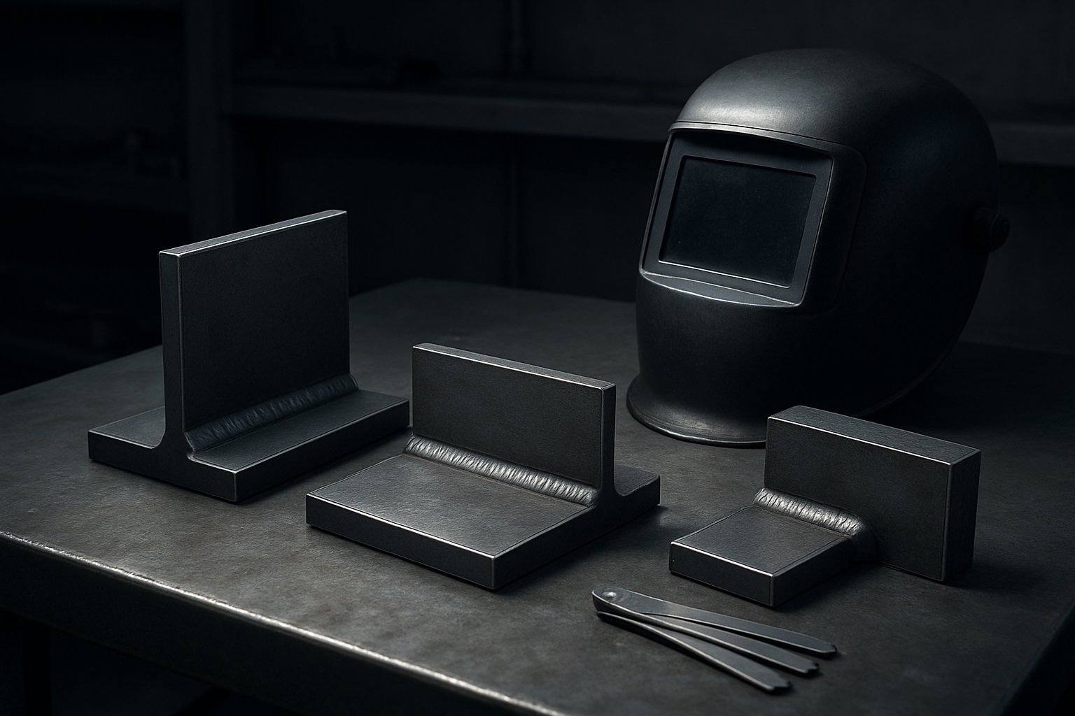
If you have ever looked at two metal parts meeting in an inside corner, you have probably seen a fillet weld. For readers asking what are fillet welds, the short answer is straightforward. If you are wondering what is a fillet weld, think of the bead laid into that corner where two members meet.
What Is a Fillet Weld
A fillet weld is a weld of roughly triangular cross-section that joins two surfaces meeting at about right angles, most often in T, lap, and corner joints.
That standard definition reflects AWS terminology summarized by Meyer Tool. In plain language, the weld fills the inside corner and fuses to both pieces. If you need to define fillet weld in shop terms, it is the common corner-filling weld used when parts are not joined edge to edge in a groove.
The wording matters because the question what is a fillet in engineering can mean different things depending on context. In general engineering, a fillet may refer to a rounded inside corner or transition radius. In welding, a fillet weld is a specific weld type, so it should not be confused with a machined radius, a decorative edge, or the food-related use of the word fillet.
Why Fillet Welds Are So Common
Fillet welds are everywhere in fabrication because the joint shapes that need them are everywhere too. They are commonly used where parts overlap or intersect, they are often accessible to the welder, and they usually require less edge preparation than many groove welds. That mix of simplicity, access, and versatility makes the weld fillet one of the most familiar forms in metalworking.
The scale of that use is substantial. TWI notes that fillet welded joints probably account for around 80% of all joints made by arc welding.
How to Recognize One on a Joint
- Its cross-section is usually roughly triangular.
- It sits in the inside corner of a joint, not in a prepared groove between edges.
- You commonly see it on T joints, lap joints, and corner joints.
- It may be placed on one side or on both sides of the joint.
- Its general purpose is to join two members where the geometry naturally creates a corner to fill.
You may also hear informal references to a weld fillet, but the idea stays the same: a bead placed in the corner between parts. Look closely at those joint shapes and the logic becomes obvious, because geometry is what makes this weld type fit so naturally.
Joint Shapes That Use Fillet Welds
The shape of the joint decides whether a fillet weld is the natural choice or not. In everyday fabrication, that usually means three familiar layouts: T-joints, lap joints, and corner joints. TWI identifies these as the common joint designs for this weld type, and they keep showing up because each one creates an inside corner the weld can fill.
T Joints Lap Joints and Corner Joints
- T-joint: One member meets the face of another at about 90 degrees, forming a welded t joint or tee weld joint. A t joint fillet weld is common because the intersection leaves a clear corner on one side or both sides.
- Lap joint: One piece overlaps another and the weld is placed along the exposed edge where they meet. Put simply, a lap joint creates the geometry for fillet welds by creating a corner at the overlap rather than an edge-to-edge seam.
- Corner joint: Two parts meet at a right angle to form an L-shape. This fillet joint is common in frames, boxes, and fabricated enclosures where the corner itself needs to be tied together.
Each of these is a fillet weld joint because the parts do not meet like a butt joint. Instead, their arrangement leaves a groove-like corner space that a fillet joint weld can occupy and fuse to both members.
Why Geometry Favors a Fillet Weld
A fillet weld works best when the joint already gives the welder a corner to fill. That is why these layouts are so common. The weld metal can be placed where the two surfaces intersect, rather than relying on heavy edge preparation. Depending on the drawing and service need, the weld may be made on a single side, both sides, or in intermittent sections. The choice usually follows geometry, access, and how the assembly is intended to carry load.
| Joint configuration | Access needs | Typical use | General advantage |
|---|---|---|---|
| T-joint | Good side access to one or both corners | Brackets, stiffeners, structural members | Simple layout for a fillet joint |
| Lap joint | Need room along the overlap edge | Thin sections, reinforcement, repairs | Easy fit when parts overlap |
| Corner joint | Access can tighten inside the corner | Frames, boxes, enclosures | Joins edges while forming shape |
Fit Up and Access Basics for Beginners
Fit-up simply means how the parts meet before welding. If the pieces sit where they should, the welder can place the bead where it belongs. If gaps are inconsistent, edges are misaligned, or the corner is too tight, the bead can drift, grow uneven, or miss one side. Access matters just as much. The torch, gun, or electrode needs enough room to reach the joint at a workable angle. Tight corners and blocked approaches make it harder to place the weld evenly, especially on a tee weld joint or inside corner.
That is where the next layer of understanding starts to matter. Once you can spot the right geometry, the important question becomes what parts of the weld you are actually looking at: the root, the toes, the face, the legs, and the throat.
Core Parts of a Fillet Weld
Those labels are the vocabulary that lets welders, inspectors, and designers talk about the same bead without guessing. The basic parts of a fillet weld are the root, toe, face, leg, and throat. Technical descriptions used here follow OpenWA Pressbooks and Weld Guru. If you can identify these parts of a weld on sight, drawings and inspection notes start to make far more sense.
Anatomy of a Fillet Weld
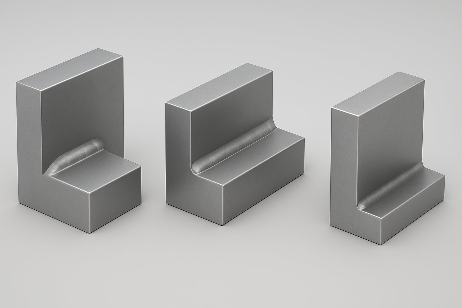
Picture a fillet weld in cross-section and you get a rough triangle. At the bottom is the weld root, opposite the exposed surface. The visible outer surface is the weld face. Where that face blends into the base metal on either side, you have the weld toe. The distance from the root to each toe is the weld leg, which is the size dimension people most often notice first. Together, these are the main parts of a fillet weld that shape how the joint is described and checked.
The face profile can vary. A fillet weld may look flat, convex, or concave. That profile affects appearance and helps explain why two welds with similar legs may not have the same useful throat.
A large-looking fillet weld can still be poorly proportioned, so size alone never tells the full quality story.
What the Root Toe Face and Throat Mean
| Term | Plain-language definition | Why it matters |
|---|---|---|
| Weld root | The bottom of the weld where the joined members meet, opposite the face. | Fit-up and throat measurements start here, so root condition matters in both fabrication and review. |
| Weld toe | The line or edge where the weld face meets the base metal. | This transition is a key visual checkpoint during inspection because it shows how the weld blends into the part. |
| Weld face | The exposed outer surface of the finished weld. | Its profile helps reveal whether the weld is flat, convex, or concave. |
| Weld leg | The distance from the weld root to the weld toe on each side of the fillet. | Leg size is the common way fillet weld size is designated on many drawings. |
| Weld throat | The shortest distance from the weld root to the weld face. On the real weld profile, this is the actual throat. | The throat relates more directly to the effective section of the weld than face appearance alone. |
| Effective throat | The throat based on the theoretical triangle inside the fillet weld, not on extra outside buildup. | It helps explain why convex reinforcement does not automatically count as more useful weld metal. |
How These Terms Affect Strength and Inspection
In shop practice, each term points to a different question. Is the weld leg large enough for the callout. Does the weld face have the intended profile. Is the weld toe blended into the base metal cleanly. Is the weld root positioned where it should be. And does the weld throat reflect the weld's real working section rather than just a bulky surface shape.
Some beginners search for the phrase throat of weld when they really mean weld throat. The idea is the same: you are looking for the shortest path from root to face, not simply the tallest-looking bead. Weld Guru explains the actual throat from the root to the face, while OpenWA Pressbooks notes that effective throat excludes extra convexity. That distinction matters in inspection, design review, and everyday discussions about whether a weld only looks big or is proportioned correctly.
Once this anatomy becomes familiar, the language on welding prints stops feeling abstract. Root, toe, face, leg, and throat begin to show up as clear instructions rather than mysterious terms beside a symbol.
How to Read a Fillet Weld Symbol
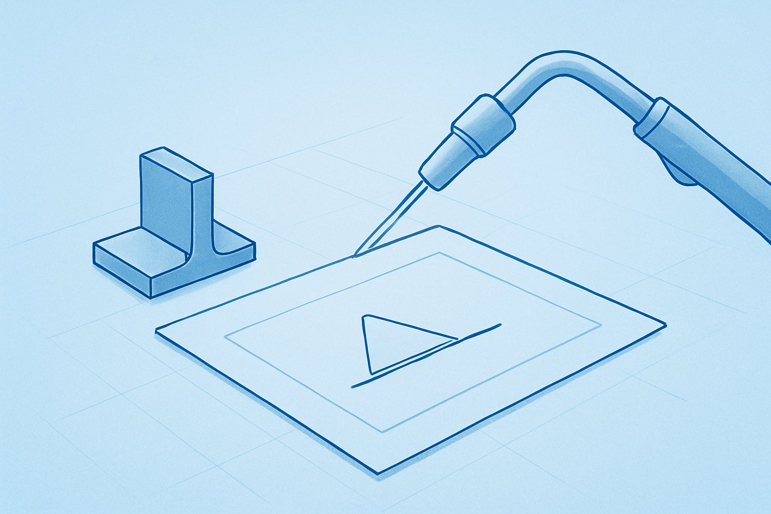
On a drawing, all that weld anatomy gets compressed into a small visual shorthand. A fillet weld symbol looks simple at first glance, but each mark has a job. As Miller explains from ANSI/AWS practice, the reference line is the anchor, the arrow points to the joint, and the basic weld symbol tells you what type of weld is required. Among common fillet welding symbols, the one beginners see most often is the small triangle.
Reading the Fillet Weld Symbol
The usual welding symbol for fillet weld work is a triangle placed on a reference line. That triangle is the symbol for fillet weld notation, but it does not work alone.
- Reference line: the horizontal line that carries the welding instruction.
- Arrow: points to the joint that needs the weld.
- Triangle symbol: identifies the weld as a fillet weld.
- Location above or below the line: shows whether the weld is on the arrow side or the other side.
- Tail, if shown: adds extra process or note information.
Both Weld Guru and Miller note the same side rule: a symbol below the reference line applies to the arrow side, and a symbol above it applies to the other side. If the triangle appears on both sides, the drawing is calling for welds on both sides of the joint.
How Size Length and Pitch Are Shown
In a typical fillet weld callout, size is placed to the left of the triangle. Length appears to the right. If the weld is intermittent rather than continuous, the callout shows length first and pitch second, separated by a dash. Pitch is the center-to-center spacing, not just the open gap between weld segments. That is the main idea behind an intermittent fillet weld symbol.
| Symbol element | Meaning |
|---|---|
| Triangle | Fillet weld required |
| Left-side dimension | Fillet weld size |
| Right-side dimension | Weld length |
| Length-pitch pair | Intermittent segment length and spacing |
| Above or below reference line | Other side or arrow side placement |
Common Callout Mistakes That Confuse Beginners
- Reading pitch as the empty space between welds instead of center-to-center spacing.
- Assuming the triangle alone gives complete instructions.
- Missing whether the symbol sits above or below the reference line.
- Confusing a continuous weld with a limited-length weld when no right-side dimension is shown.
In other words, the weld symbol for fillet welds tells you location and extent, not just weld type. That small triangle answers one question on the print. The next question is bigger: why a fillet is specified there at all, and when a groove weld would be chosen instead.
Fillet vs Groove Weld at a Glance
A symbol tells you what the drawing calls for, but not why that choice makes sense. In real fabrication, the fillet vs groove weld decision starts with how the parts meet. A fillet weld is placed in an inside corner, usually on T-, lap-, and corner-joint work. A groove weld is deposited in a groove between members, most commonly in butt-joint work where edges meet in the same plane, though prepared T-joints and corner joints can use groove welds too. For many readers comparing a groove weld vs fillet weld, that is the clearest first split: corner geometry versus prepared edge geometry.
Fillet Weld vs Groove Weld at a Glance
The practical groove weld vs fillet weld difference is usually easy to spot on the shop floor. Fillet welds often need little or no edge preparation and are common in high-volume fabrication. Miller notes they are the most common welds on structural jobsites and are generally inspected visually. Groove welds make up a smaller share of welds, but they are important where the application calls for joint penetration through the thickness of the members. They also tend to need more fit-up control, more preparation, and more verification.
| Aspect | Fillet weld | Groove weld |
|---|---|---|
| Common joint type | T-joints, lap joints, corner joints | Butt joints most often, plus prepared T-joints and corner joints |
| Access needs | Needs access to the inside corner | Needs access to prepared edges and root area; single-sided access can be demanding |
| Preparation needs | Often little or no edge prep | Often square, V-, or U-groove preparation, plus tighter fit-up |
| Typical use | Shear tabs, cover plates, bracing connections, column bases, seam and stitch welds | Moment connections, column splices, HSS member connections |
| General tradeoffs | Simpler and faster to produce in many cases | More skill, time, and inspection attention, especially for full-penetration work |
When CJP and PJP Matter
If the term cjp in welding is unfamiliar, it simply refers to complete joint penetration. A CJP weld is a groove-weld condition where the weld metal extends through the full thickness of the joint. A PJP weld reaches only partway through the joint thickness. Miller explains that the strength required by the application often determines when a more complicated complete joint penetration welding detail is chosen instead of a typical fillet weld. In single-sided HSS work, Steel Tube Institute notes that fit-up, backing details, access, skill, and qualification requirements can make CJP welds especially difficult and expensive.
That does not mean every demanding joint automatically needs a cjp weld. Some designs use a pjp weld, and some use a PJP groove with fillet reinforcement. The key point is simpler: CJP and PJP belong to groove-weld thinking, where penetration depth and joint preparation are part of the specification.
Choosing Based on Access Preparation and Load Path
Selection gets clearer when you picture the actual assembly. If the parts naturally create an inside corner and both members are reachable, a fillet weld is often the cleaner solution. If the edges must be joined through the section, the joint may call for a groove weld, especially in butt-joint fabrication or prepared T-joints. That is why the fillet vs groove weld choice is not just a vocabulary issue. It depends on access, required preparation, and how the load is intended to pass through the joint. Those same factors also shape which welding process works best, because a prepared groove and a simple corner fillet do not behave the same once the arc starts.
Fillet Welding Processes and Position Challenges
The drawing may call for a fillet weld, but the shop still has to decide how to make it. People searching 'welding fillet weld' or 'welding fillet joint' questions are usually trying to solve the same practical problem: which process gives enough access, control, and fusion for the joint in front of them. In real fillet welding, MIG, TIG, stick, and flux-cored processes can all be used, but they do not behave the same once position, wind, fit-up, and puddle control enter the picture. Guidance from Miller shows that process choice and transfer mode help determine which fillet weld positions are practical.
MIG TIG Stick and Flux Cored in Fillet Welding
| Process | Common fit for fillet welds | Main advantage | Practical limitation |
|---|---|---|---|
| MIG, or GMAW | Shop fabrication, production work, clean steel joints | Fast and relatively easy to learn, with clean-looking welds | Shielding gas can be disturbed by wind, and transfer mode matters. Short-circuit and pulsed MIG can be used out of position, while spray transfer is generally limited to flat and horizontal welding. |
| TIG, or GTAW | Thin material, precise fit-up, appearance-sensitive work | Highest control over bead placement and weld appearance | Slower and more skill-intensive than the other common processes |
| Stick, or SMAW | Outdoor repairs, thicker sections, less-than-perfect surfaces | Simple setup and good tolerance for rusty or dirty steel | More spatter and cleanup, with less visual neatness than TIG or MIG |
| Flux-cored, or FCAW | Outdoor work, thicker steel, heavier fabrication | Fast deposition and good performance in windy conditions, especially with self-shielded wire | More smoke and post-weld cleanup. Position capability depends heavily on the filler metal used. |
That difference shows up quickly on a fillet welded bracket, tab, or stiffener. A fast process can still give poor results if it does not suit the joint access or the position.
Position and Access Challenges
Flat 1F is usually the easiest because gravity is not pulling the puddle out of the joint. Horizontal 2F is still manageable, but Miller notes that a 45-degree work angle to the joint helps focus heat where the two members meet, and too much heat can make the bead sag. Vertical 3F and overhead 4F demand much tighter puddle control. Vertical work often needs reduced wire feed speed and voltage so the weld metal does not fall, while overhead welds are commonly run cooler for the same reason. Access can be just as limiting as position. If a flange, web, or corner blocks the gun, torch, or electrode, bead placement drifts, and one leg can grow at the expense of the other.
Technique Variables That Change the Result
- Travel angle: If the wire or electrode sits too far to one side, heat is no longer centered at the root. That makes lack of fusion more likely on the cooler side of the joint.
- Heat input: Too little heat can leave the bead sitting high on the surface. Too much can make the puddle overly fluid, increasing sag, overlap, or an excessively convex face.
- Fit-up: Notes from TWI show that poor fit-up can reduce throat thickness, and oversized fillet welds can add cost and distortion without automatically improving the joint.
You may even hear the loose shop phrase 'throat welding' when people mean building the useful throat instead of simply piling metal onto the face. That is the key visual lesson here: a larger-looking bead is not automatically a better one. The real question is what dimension the weld actually achieved, and that starts with leg size, actual throat, and effective throat.
How to Measure Fillet Weld Size
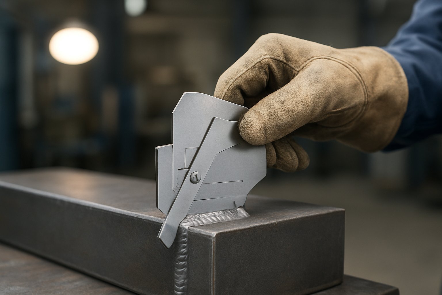
A fillet weld can look large and still miss the section the joint actually needs. On the joint itself, measurement starts with what you can identify by eye: the root, the toes, and the weld face. Those landmarks turn abstract weld dimensions into physical features you can inspect. KOBELCO notes that fillet weld size is measured by the legs of the largest right triangle that can be inscribed within the weld cross-section, which is why weld leg size is usually the first checkpoint. Good weld dimensioning on a print only works when the finished bead is measured from those same points on the real joint.
Leg Size Throat and Effective Throat Explained
Start with the legs, because they are the easiest part to see. In leg size welding inspection, each leg is the distance from the root to the toe on one side of the fillet. That root-to-toe distance is what commonly defines the stated weld size on a drawing. The actual throat is different. An AWS CWI guide describes the throat as the shortest distance between the root face and the face of the weld. KOBELCO also shows the design side of the same idea: for an equal-leg fillet, the theoretical throat comes from the inscribed right triangle, and in the standard equal-leg case it is 0.7 times the fillet weld size. In design review, that throat value is paired with effective weld length. If both legs are intended to match, compare both sides together. If the joint is specified with unequal legs, inspect each side against its own requirement instead of assuming the larger side tells the whole story.
| Measurement term | Part of the weld to inspect | What it confirms |
|---|---|---|
| Leg size | Root to toe on each side | The called-out fillet weld size or weld size |
| Actual throat | Shortest path from root area to weld face | The real section achieved by the finished profile |
| Theoretical or effective throat basis | Inscribed triangle within the cross-section | The design throat used with effective weld length |
A Step by Step Way to Think About Measurement
- Clean the weld surface so dirt, rust, or slag do not interfere with the reading.
- Identify the root, both toes, and the weld face before you touch the bead with a gauge.
- Measure the weld leg size from root to toe. A fillet weld gauge, bridge cam gauge, or multipurpose welding gauge can be used for this step.
- Check the actual throat as the shortest distance from the root area to the weld face. A throat gauge or pass-fail fillet gauge can help verify it.
- Look at the overall profile while measuring. KOBELCO lists leg or size, throat, convexity, and concavity as part of fillet weld quality control.
What Inspectors Look For Before Calculations
Visual inspection is the fastest starting point, but the AWS CWI guide notes that visual checks alone are not always accurate. Before anyone gets into calculations, the practical questions are simpler. Is the surface clean enough to read. Are the toes easy to locate. Does the face profile make the fillet weld dimensions clear, or is the bead shape hiding the true geometry. Is the fit-up consistent enough that the root can be identified with confidence. Those observations make measurement more reliable and help explain why two welds that look similar can produce different readings. And when a leg or throat check comes up short, the profile itself usually reveals the cause, which is why common fillet weld defects deserve a closer look.
Common Fillet Weld Defects and Fixes
Measurement tells you whether a fillet weld reached the intended size. Profile tells you why it may still be wrong. On real parts, many defects can be spotted before any gauge comes out. The shape of the bead, the condition of the welding toe, and the way the weld ties into both members all leave clues. Guidance from Fractory, TWI, and UNIMIG lines up on the basics: poor fit-up, incorrect heat, bad angle control, dirty surfaces, and rushed travel speed are common reasons a fillet weld looks wrong or performs poorly.
Defects You Can Recognize on a Fillet Weld
You do not need diagrams to identify many common problems. If you study enough weld examples, the patterns become familiar.
- Undercut: a groove melted into the base metal along the toe of the weld.
- Overlap in welding: filler metal rolls over the base metal and appears to hang past the welded edges instead of blending into them.
- Lack of fusion: the bead appears to sit on the surface rather than fully tying into one side of the joint or between passes.
- Unequal legs: one leg is visibly larger, often because the arc favored one member more than the other.
- Excessive convexity: an overly crowned bead, sometimes called a ropey convex weld.
- Overly concave profile: a hollowed face, or concave weld, that looks scooped inward.
| Defect | What it looks like | Why it matters | First adjustment to check |
|---|---|---|---|
| Undercut | Groove at the weld edge beside the bead | Reduces section at the toe and can raise stress concentration | Lower excessive heat or slow down enough to refill the edge |
| Overlap | Metal spills over without fusing into the base | Creates a false impression of size without proper fusion | Increase heat if too cold and correct work angle |
| Lack of fusion | Bead sits against one member with visible unfused areas | Weak connection between weld metal and base metal | Check heat input, torch angle, and bead placement |
| Unequal legs | One side of the fillet is noticeably longer | Can reduce intended throat on the smaller side | Re-center the arc and review access restrictions |
| Excessive convexity | High crowned bead standing proud of the joint | Extra buildup does not automatically improve the joint | Check for cold weld metal, slow travel, or too much deposited filler |
| Overly concave profile | Face dips inward between the toes | May indicate the profile is too thin through the center | Reduce excessive heat or overly slow travel |
Why Undercut Overlap and Lack of Fusion Happen
Fractory describes undercut as commonly linked to high arc voltage, wrong electrode angle, and high travel speed. UNIMIG adds that too long an arc and not enough filler can deepen that groove at the toe of the weld. Overlap points in the other direction. Fractory describes it as excess metal spreading around the bead without properly mixing with the base metals, while UNIMIG ties it to a weld that is too cold, too full, or poorly angled.
Lack of fusion often starts with low heat input, poor bead placement, or the wrong torch angle. Fractory notes that incorrect joint angle and an oversized weld pool can also contribute. Restricted access makes all of this worse. If the gun or electrode cannot sit at a workable angle, one side of the joint gets the heat and the other side gets a surface deposit. That is also how unequal legs show up, especially where gravity pulls the molten pool off center. TWI notes this asymmetry is a known issue in horizontal-vertical fillet welding.
Fit-up and cleanliness matter just as much. Dirty surfaces can contaminate the weld pool. Poor fit-up changes the real geometry before the arc even starts. TWI shows that excessive gap in fillet-welded joints reduces the effective leg and throat, so the bead may look acceptable while the inside geometry is not.
Corrective Actions for Better Weld Profile
- Clean both joint faces before welding so contamination does not interfere with fusion.
- Check fit-up first. If the parts are separated or misaligned, technique alone may not fix the result.
- Keep the arc centered so both welded edges receive heat.
- Match travel speed to the puddle. Too fast can cause undercut or lack of fusion. Too slow can produce a convex weld or excessive buildup.
- Watch the bead tie-in at each weld edge, not just the face appearance.
- If access is tight, reposition the part or change approach before blaming settings alone.
That is why visual quality is never just cosmetic. Repeated profile problems usually point to deeper issues in setup, access, fixturing, or operator consistency. In one-off repair work that is frustrating. In production welding, it becomes a manufacturing question.

Where Fillet Welds Fit in Automotive Fabrication
In production, a good-looking fillet weld is only the starting point. On chassis brackets, mounts, tabs, and crossmembers, the real test is whether every welded part lands in the same location, cycle after cycle, so downstream assembly still fits. Automotive welding fixtures are built for exactly that purpose: they secure and position parts during welding so accuracy and consistency are maintained. That matters whether the print calls for a continuous bead, an intermittent fillet weld, or a double fillet weld on both sides of a bracket. It matters in structural assemblies too, because inconsistent structural welds can create stack-up problems, rework, and distortion.
Why Fillet Weld Repeatability Matters in Chassis Parts
Automotive parts are often thin and easy to move with heat. The same fixture source notes that proper positioning and clamping help reduce welding deformation, which is critical when holes, tabs, and mounting faces must line up later in assembly. Add robotic welding to that setup and the benefit grows: programmed motion and controlled parameters support repeatable weld placement across high-volume runs. In practice, that means a bracket using an intermittent weld or a double fillet weld is more likely to come off the line with the same geometry every time.
What to Look for in a Welding Manufacturing Partner
- Process capability that matches the part, such as MIG, TIG, spot, or robotic arc welding.
- Material range for the metals in your program, including steel, aluminum, and similar fabrication needs.
- Fixture and tooling control that holds parts in a repeatable position before and during welding.
- Quality systems with traceability and automotive-relevant certification when required.
- Production consistency across volume, not just one acceptable sample.
Using a Supplier Resource to Evaluate Custom Welding Capabilities
A useful supplier page should show more than finished parts. It should also reveal how the company manages fixturing, repeatability, and quality. One example is Shaoyi Metal Technology, which presents custom automotive welding around robotic welding lines and an IATF 16949 certified quality system for steel, aluminum, and other metals. That is the kind of information buyers should look for when sourcing a structural weld program, a skip weld layout, or any repeated chassis component. It also helps answer a related question some readers have, what is a field weld. In simple terms, a field weld is made at the installation site, while most automotive fillet-welded parts are produced under controlled shop conditions where fixturing, distortion management, and inspection are easier to keep consistent.
Fillet Weld FAQs
1. What are fillet welds used for?
Fillet welds are commonly used where two metal parts meet in a corner rather than edge to edge. You will often see them on T-joints, lap joints, and corner joints in brackets, tabs, frames, mounts, enclosures, and many structural or automotive assemblies. They are popular because the joint shape naturally gives the welder a place to deposit weld metal without the extra edge preparation many groove welds need.
2. How do fillet welds differ from groove welds?
The main difference is joint geometry. A fillet weld joins surfaces that meet at an angle, usually around 90 degrees, while a groove weld fills a prepared space between edges, often in butt-joint work. In practice, fillet welds are usually chosen for accessible corner-type joints, while groove welds come into the picture when penetration, edge preparation, and load transfer through the joint thickness matter more.
3. How do you measure a fillet weld?
A practical check starts by locating the root, the toes, and the weld face on the actual joint. From there, the most common measurement is leg size, taken from the root to each toe, followed by throat checks when needed. Inspectors also look at the weld profile and fit-up before trusting a gauge reading, because a bead can appear large while still being poorly shaped or uneven.
4. What does a fillet weld symbol tell you?
A fillet weld symbol uses a triangle on a reference line to show that the joint needs a fillet weld. The arrow identifies the location, and the symbol position above or below the line indicates which side of the joint is involved. Additional notation can show weld size, length, and intermittent spacing, so the symbol communicates not just the weld type but also where and how much welding is required.
5. What should manufacturers check when choosing a welding partner for fillet-welded parts?
For production parts, the key checks are process capability, fixture control, material range, quality systems, and repeatability across volume. A good supplier should show how it manages distortion, part location, and consistent weld placement, not just finished photos. In automotive work, for example, a supplier resource such as Shaoyi Metal Technology's welding page is useful because it highlights robotic welding capability, steel and aluminum coverage, and an IATF 16949 quality system, which are the kinds of details buyers should verify during sourcing.