 Small batches, high standards. Our rapid prototyping service makes validation faster and easier —

Welding Sheet Metal Fabrication: Essential Points From Setup To Flawless Finish
Understanding Sheet Metal Welding Fundamentals
Ever tried welding a thin automotive panel only to watch it warp before your eyes? You're not alone. Welding sheet metal fabrication demands a completely different mindset than working with thick plate steel. While thicker materials forgive excess heat and sloppy technique, thin gauges punish every mistake instantly.
In simple terms, welding sheet metal means joining thin metal panels using low heat, short welds, and precise control to avoid burn-through and distortion. This process typically involves materials ranging from 24 gauge (0.024 inches) to 10 gauge (0.135 inches), though some applications extend from 30 gauge up to 8 gauge. Understanding welding basics for these thin materials sets the foundation for everything that follows.
What Makes Sheet Metal Welding Different
The fundamental difference between welding and sheet metal fabrication lies in how heat behaves. Thick plate steel acts like a heat sink, absorbing and dissipating thermal energy gradually. Sheet metal? It heats up almost instantly and transfers that energy across the entire workpiece before you can react.
Think of it this way: when you weld sheet metal, you're essentially racing against physics. The thin material absorbs heat so quickly that a half-second too long in one spot can melt right through your workpiece. This is why technique matters far more than raw power when working with these materials.
Multiple industries depend heavily on precise sheet metal welding every day:
- Automotive manufacturing: Body panels, patch repairs, and structural brackets require flawless welds without visible distortion
- HVAC systems: Ductwork fabrication demands airtight seams across long runs of thin galvanized steel
- Appliance production: Washing machines, refrigerators, and ovens rely on welded sheet metal enclosures
- Architectural metalwork: Decorative panels, facades, and custom fixtures need show-quality appearance
Why Thickness Changes Everything in Welding
When you weld sheet metal, thickness dictates nearly every parameter you'll use. A setting that works perfectly on 14-gauge steel will blow holes through 22-gauge material. Understanding the different types of welding in sheet metal applications helps you match your approach to the specific thickness you're working with.
The relationship between welding and sheet metal creates unique challenges that thicker materials simply don't present:
- Heat sensitivity: Thin metal reaches melting temperature almost immediately, leaving zero margin for error in your heat input calculations
- Distortion control: Uneven heating causes panels to buckle, wave, and twist, often ruining hours of careful fabrication work
- Aesthetic requirements: Many sheet metal applications remain visible in the final product, demanding clean, consistent bead appearance
- Joint accessibility: Thin edges and tight corners common in sheet metal work require precise torch angles and steady hand control
- Burn-through prevention: Unlike thick plate that tolerates dwelling, sheet metal demands constant movement and minimal heat concentration
These challenges explain why professional fabricators approach sheet metal welding as a specialized skill set. The same welder who produces beautiful structural joints on heavy plate might struggle initially with thin automotive panels. Mastering this discipline requires understanding that less heat, shorter welds, and patience will always outperform brute force.
Complete Welding Methods for Sheet Metal Applications
Now that you understand why thin materials demand specialized treatment, the next question becomes: which welding method should you actually use? The answer depends on your specific project requirements, skill level, and quality expectations. Let's break down every viable option so you can match the right technique to your application.
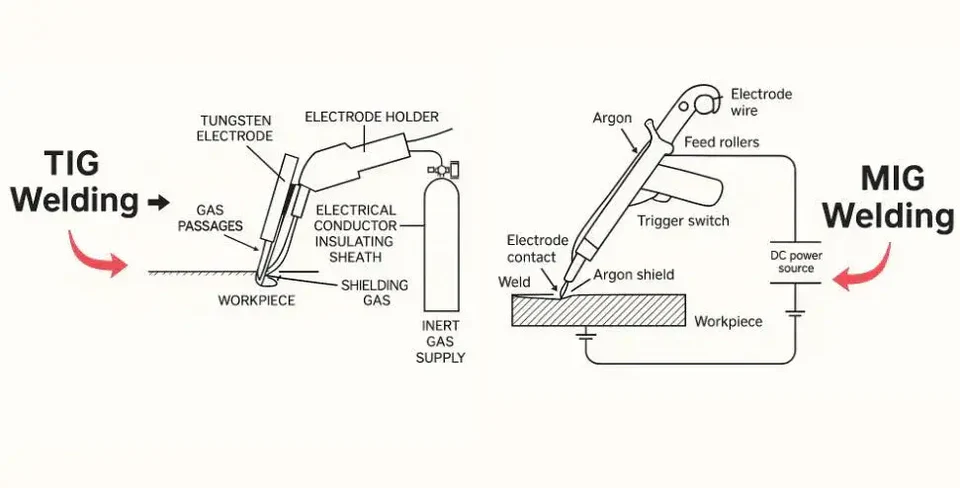
MIG and TIG Methods Compared
When comparing tig and mig welding for sheet metal, you're essentially choosing between speed and precision. Both processes work exceptionally well on thin materials, but they excel in different situations.
MIG welding sheet metal offers faster deposition rates and a shorter learning curve. The process feeds wire continuously through the gun, making it easier to maintain consistent welds across long seams. For production environments where time matters, MIG delivers. According to welding industry experts, MIG (also called GMAW) uses shielding gas formulated from the welding gun to protect against contamination, with common options including 75% argon/25% CO2 mixtures that provide less heat input than pure CO2.
Here are some practical tips for mig welding thin materials:
- Use the smallest wire diameter possible while maintaining adequate deposition, typically 0.023 inch for most sheet metal work
- Push the torch rather than pull to direct heat toward the cooler edge of the weld puddle
- Travel in a straight line at the fastest speed that still allows proper penetration
- Keep arc length and voltage as low as possible to minimize heat input
TIG welding sheet metal sacrifices speed for superior control and weld appearance. The tig weld mig weld comparison becomes clear when aesthetics matter: TIG produces cleaner, more precise beads with virtually no spatter. This process uses non-consumable tungsten electrodes with high heat tolerance, allowing welding at low current on material as thin as 0.005 inches. Industries like aerospace, medical, and high-end automotive rely on TIG for this reason.
Both processes offer pulsed variations that fluctuate current from low to high instead of maintaining consistent flow. This produces smoother ripples in the weld bead, faster travel speeds, and reduced heat input, which helps decrease distortion risk significantly.
Specialty Techniques for Precision Work
Beyond the standard MIG and TIG approaches, experienced sheet metal welders employ several specialty techniques that address specific challenges.
Spot welding fires electrical current through two pins pinching sheet metal layers together. As the metal heats, it melts into a coin-shaped nugget at the contact point, fusing the materials. This technique works best on materials between 0.020 to 0.090 inches thick and eliminates the need for filler material entirely. Production facilities favor spot welding because it delivers Class A finishes without grinding.
Skip welding represents a heat management strategy rather than a distinct welding process. Instead of running one continuous bead across a joint, you create short welds at different points that eventually connect. This allows heat to dissipate between welds, dramatically reducing distortion risk. Leave the metal to cool for a second or two between welds before moving to the next section.
Plug welding handles overlapping panels where spot welding can't reach or materials exceed 0.090-inch thickness. The welder cuts holes into one sheet, then fills them with weld metal that fuses both layers together. The result is a smooth finish similar to spot welding but applicable to thicker materials.
Flux welding sheet metal using flux-core wire offers outdoor versatility since the flux provides its own shielding, eliminating the need for external gas in windy conditions. However, this method generates more heat and spatter than solid wire MIG, making it less ideal for thin gauges unless you use specifically designed small-diameter flux-core wire.
| Method | Best Material Thickness | Skill Level Required | Speed | Weld Appearance | Typical Applications |
|---|---|---|---|---|---|
| MIG (GMAW) | 20 gauge to 10 gauge | Beginner to Intermediate | Fast | Good, minimal cleanup | Automotive panels, HVAC, general fabrication |
| TIG (GTAW) | 30 gauge to 10 gauge | Intermediate to Advanced | Slow | Excellent, show quality | Aerospace, medical, decorative work |
| Spot Welding | 0.020" to 0.090" | Beginner | Very Fast | Clean, no grinding needed | Production assembly, enclosures |
| Plug Welding | Above 0.090" | Intermediate | Moderate | Good, smooth finish | Overlapping panels, structural joints |
| Flux-Core | 18 gauge to 10 gauge | Beginner to Intermediate | Fast | Fair, requires cleanup | Outdoor repairs, structural work |
Each method carries specific limitations on thin materials. MIG struggles below 24 gauge without careful parameter adjustment. TIG demands patience and steady hands that beginners often lack. Spot welding only works on overlapping joints, not butt welds. Understanding these tradeoffs helps you select the right approach before striking your first arc.
With your welding method selected, the next critical decision involves matching your technique to the specific material you're joining, since aluminum, stainless steel, and galvanized steel each demand unique considerations.
Material-Specific Welding Guidelines and Techniques
Choosing the right welding method is only half the equation. The material sitting on your workbench dictates everything from shielding gas selection to filler wire compatibility. Welding steel behaves completely differently than welding aluminum, and ignoring these distinctions leads to failed joints, wasted materials, and frustrating rework.
Let's break down exactly what each common sheet metal material demands from your welding process.
Carbon Steel and Mild Steel Techniques
Good news first: carbon steel and mild steel represent the most forgiving materials you'll encounter when welding sheet steel. These materials tolerate a wider range of parameters and forgive minor technique errors that would ruin other metals.
Steel for welding in sheet form typically responds well to both MIG and TIG processes. The key considerations include:
- Shielding gas: A 75% argon/25% CO2 mix provides excellent arc stability and minimal spatter on thin sections
- Filler wire: ER70S-6 works as the go-to choice for most mild steel applications, offering good deoxidizers that handle light surface contamination
- Heat management: While more forgiving than other materials, thin carbon steel still warps under excessive heat, so maintain steady travel speed
- Surface preparation: Remove mill scale and rust before welding to prevent porosity and weak fusion
Carbon steel's predictable behavior makes it ideal for beginners learning proper technique before tackling more demanding materials.
Aluminum and Stainless Steel Challenges
Aluminum frustrates many welders because its properties defy conventional welding metal logic. According to Pennsylvania Steel Co., pure aluminum melts at just 1200°F, but the oxide layer coating its surface melts at 3700°F. This massive temperature gap creates serious problems when welding aluminum with a torch or any other heat source.
The oxide layer must be removed before welding, or you'll end up pushing molten aluminum around without achieving proper fusion. Aluminum's high thermal conductivity compounds the challenge, pulling heat away from the weld zone almost as fast as you apply it. TIG welding with AC current and pure argon shielding delivers the best results for thin aluminum sheet, though MIG works for faster production on thicker gauges.
Stainless steel presents different obstacles. Heat input and discoloration become your primary concerns. As The Fabricator explains, weld color indicates heat input quality: straw-colored welds signal acceptable heat levels, light to medium blue suggests borderline conditions, and dark blue to black indicates excessive heat with carbon precipitation.
Stainless steel has lower heat transfer rates than carbon steel, meaning the weld joint stays at elevated temperatures longer. This extended heat exposure increases discoloration risk and potential material degradation. Keep travel speeds high and heat input below 50 kJ/inch for most applications.
Galvanized steel introduces hazardous fume considerations that other materials don't require. The zinc coating that provides corrosion resistance vaporizes during welding, producing toxic zinc oxide fumes. According to Marco Specialty Steel, using a respirator is absolutely non-negotiable when MIG welding galvanized sheet metal, and the work area requires excellent ventilation.
Beyond safety concerns, the zinc coating interferes with fusion and causes porosity. Skilled welders either remove the galvanizing from the weld zone beforehand or use specialized filler materials designed for coated steels. After welding, the exposed area loses corrosion protection and typically requires re-galvanizing or protective coating application.
| Material Type | Recommended Method | Shielding Gas | Filler Wire Type | Special Considerations |
|---|---|---|---|---|
| Carbon/Mild Steel | MIG or TIG | 75% Ar/25% CO2 | ER70S-6 | Remove mill scale; most forgiving material |
| Stainless Steel | TIG preferred, MIG acceptable | Helium/Ar/CO2 blend or 98% Ar/2% CO2 | ER308L or ER316L (match base metal) | Control heat input below 50 kJ/in; monitor discoloration |
| Aluminum | TIG (AC) preferred | 100% Argon | ER4043 or ER5356 | Remove oxide layer; preheat thick sections; use AC current |
| Galvanized Steel | MIG with proper ventilation | 75% Ar/25% CO2 | ER70S-6 or silicon bronze | Mandatory respirator use; remove coating when possible; re-galvanize after |
Understanding these material-specific requirements prevents costly mistakes and ensures your welds perform as intended. With the right material knowledge in place, you're ready to dial in the precise parameter settings that bring everything together.
Essential Parameter Settings and Reference Tables
You've selected your welding method and matched it to your material. Now comes the question that separates frustrating trial-and-error sessions from clean, consistent welds: what settings should you actually use? Welding sheet metal with mig welder or TIG equipment demands precise parameter control, and vague guidelines like "turn it down for thin stuff" won't cut it when you're staring at expensive material.
The following reference tables and guidelines give you concrete starting points. Remember, these numbers represent baseline settings that you'll fine-tune based on your specific equipment, joint configuration, and working conditions.
Dialing In Your Amperage and Voltage
The relationship between amperage and material thickness follows a simple rule that works surprisingly well as a starting point. According to Miller Electric, each 0.001 inch of material thickness requires approximately 1 amp of output. This means 0.125-inch material needs roughly 125 amps to achieve proper penetration.
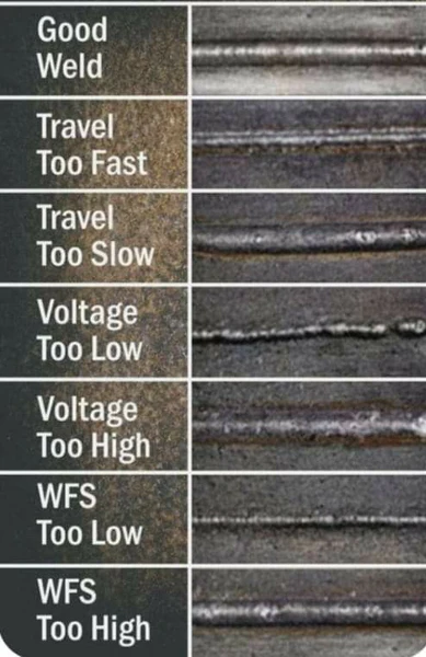
Voltage controls bead width and height. Too high, and you'll see poor arc control with inconsistent penetration and a turbulent weld pool. Too low creates excessive spatter, convex bead profiles, and poor tie-in at the weld toes. When mig welding thin metal, start with lower voltage settings and increase gradually until the arc sounds like steady, sizzling bacon rather than loud popping or harsh hissing.
For TIG applications, the "1 amp per thousandth" rule applies similarly to carbon steel. As noted by experienced welding instructors, this guideline holds true up to around 0.125 inches, but breaks down on thicker sections. Material type also affects requirements: aluminum demands more amperage than carbon steel, while stainless steel typically requires less.
Joint type influences your amperage selection too. A tee joint pulls heat into two directions, requiring more power than an outside corner joint where heat concentrates at the weld zone. Vertical position welds often need reduced amperage since slower travel speeds increase heat input per inch of weld.
Wire Speed and Gas Flow Optimization
Wire feed speed directly controls amperage in MIG welding, which means it also determines penetration depth. Setting the wire for wire welder too high causes burn-through on thin materials, while too slow results in poor fusion and weak joints.
Miller Electric provides a useful formula for calculating starting wire speed: multiply your amperage by a factor based on wire diameter. For 0.023-inch wire, multiply by 3.5 inches per amp. For 0.030-inch wire, use 2 inches per amp. So if you're welding 18-gauge steel (roughly 0.048 inches) at about 48 amps with mig welding wire 023, your starting wire speed calculates to approximately 168 inches per minute.
Selecting the right mig wire size for sheet metal depends on your amperage range and material thickness:
- 0.023-inch wire: Ideal for 30-130 amps, covering most sheet metal from 24 gauge to 14 gauge
- 0.030-inch wire: Works well for 40-145 amps, better for 16 gauge to 10 gauge applications
- 0.035-inch wire: Handles 50-180 amps, generally too large for material thinner than 14 gauge
The 023 flux core welding wire option exists for outdoor work where wind makes gas shielding impractical, though solid wire with proper shielding gas produces cleaner results on thin materials.
For tig weld wire selection, filler rod diameter typically matches or stays slightly smaller than your base material thickness. Using oversized filler adds excessive material that requires more heat to melt, increasing distortion risk.
Shielding gas flow rates depend on cup size and welding environment. A practical guideline suggests 2-3 CFH per cup size number. A #8 cup needs 16-24 CFH, while a smaller #5 cup works well with 10-15 CFH. Excessive gas flow on aluminum creates noisy, erratic arcs, while insufficient flow allows oxide contamination.
| Gauge/Thickness | Amperage Range | Voltage | Wire Speed (IPM) | Wire Diameter | Gas Flow Rate (CFH) |
|---|---|---|---|---|---|
| MIG Settings (Mild Steel, 75/25 Ar/CO2) | |||||
| 24 gauge (0.024") | 25-35 | 14-15V | 90-120 | 0.023" | 15-20 |
| 22 gauge (0.030") | 30-40 | 14-16V | 105-140 | 0.023" | 15-20 |
| 20 gauge (0.036") | 35-50 | 15-17V | 125-175 | 0.023" | 18-22 |
| 18 gauge (0.048") | 45-65 | 16-18V | 150-200 | 0.023-0.030" | 18-22 |
| 16 gauge (0.060") | 55-80 | 17-19V | 180-250 | 0.030" | 20-25 |
| 14 gauge (0.075") | 70-100 | 18-20V | 200-300 | 0.030" | 20-25 |
| 12 gauge (0.105") | 90-130 | 19-21V | 280-380 | 0.030-0.035" | 22-28 |
| 10 gauge (0.135") | 110-150 | 20-22V | 350-450 | 0.035" | 25-30 |
| TIG Settings (Carbon Steel, 100% Argon) | |||||
| 24 gauge (0.024") | 15-25 | N/A | N/A | 1/16" filler | 10-15 |
| 20 gauge (0.036") | 30-45 | N/A | N/A | 1/16" filler | 12-18 |
| 18 gauge (0.048") | 40-55 | N/A | N/A | 1/16" filler | 15-20 |
| 16 gauge (0.060") | 50-70 | N/A | N/A | 1/16-3/32" filler | 15-20 |
| 14 gauge (0.075") | 65-90 | N/A | N/A | 3/32" filler | 18-22 |
| 12 gauge (0.105") | 85-115 | N/A | N/A | 3/32" filler | 18-25 |
| 10 gauge (0.135") | 110-145 | N/A | N/A | 3/32-1/8" filler | 20-25 |
Heat input and travel speed share an inverse relationship that determines weld quality. Faster travel reduces heat input per inch, minimizing distortion but potentially causing lack of fusion. Slower travel increases penetration but risks burn-through and excessive warping. The goal is finding the fastest speed that still produces complete fusion with acceptable bead appearance.
Always make test welds on scrap material before touching your actual workpiece. Listen to the arc, watch the puddle formation, and examine the completed bead. A good weld shows flat to slightly convex profile, consistent width, and smooth tie-in at the edges where weld metal meets base metal.
Even with perfect parameters dialed in, problems can still arise during welding. Knowing how to identify and fix common defects quickly separates proficient welders from those who waste materials on repeated failures.
Troubleshooting Common Sheet Metal Welding Defects
Your parameters are dialed in, your material is prepped, and you're ready to weld. Then something goes wrong. Maybe you punch straight through your workpiece, or perhaps the finished panel looks like a potato chip. Welding thin metal amplifies every mistake, and knowing how to weld sheet metal successfully means understanding what causes defects and how to fix them before they ruin your project.
The following troubleshooting guide covers the most common problems you'll encounter, their root causes, and actionable solutions that actually work. Whether you're using a welder for thin metal applications or tackling thicker gauges, these techniques apply across the board.
Preventing Burn-Through and Warping
Burn-through represents the most frustrating defect in thin metal welding. According to UNIMIG, burn-through occurs when the filler metal melts through the base metal and protrudes out the other side, leaving a hole. This defect significantly reduces weld strength and integrity, often requiring complete rework or replacement of the damaged section.
Burn-through happens more frequently on thinner metals, materials with low heat conductivity like stainless steel, and during root passes. The main culprit? Too much heat in the metal.
-
Causes of burn-through:
- Amperage or voltage set too high for material thickness
- Travel speed too slow, allowing heat to concentrate in one spot
- Poor joint preparation with gaps larger than necessary
- Excessive grinding that removes too much base metal
- Improper weave patterns that pause too long at any point
- Using high heat input processes like stick welding on thin materials
-
Solutions for burn-through:
- Reduce amperage or voltage and wire feed speed immediately
- Increase travel speed to move heat along the joint faster
- Use backing plates made of copper or aluminum to pull heat away from the weld zone
- Switch to TIG welding for better heat control on extremely thin materials
- If burn-through occurs, attach a backing plate and fill the hole with reduced settings before grinding flush and re-welding
Warping and distortion plague nearly every thin metal welding project. When you tig weld sheet metal or use any other process, you're creating a localized blast furnace where temperatures exceed 2,500°F. The metal around your weld puddle expands rapidly, then contracts as it cools. This expansion-contraction cycle happens in seconds, but the effects become permanent.
According to Hotean, heat input determines everything when controlling distortion. The more heat you pump into thin material, the wider the affected zone becomes, and larger welds mean more shrinkage force pulling your panels out of alignment.
-
Causes of warping:
- Excessive heat input concentrated in one area
- Long continuous welds that allow heat to accumulate
- Unbalanced welding sequences that create uneven stress distribution
- Inadequate clamping or fixturing during welding
- Incorrect tacking sequence that concentrates stress points
-
Solutions for warping:
- Use skip welding patterns: weld 2-inch segments with gaps between them, returning later to fill the spaces
- Apply back-step welding technique by welding short segments, then stepping back to weld the next segment toward your starting point
- Install copper backing bars that serve double duty as heat sinks and burn-through prevention
- Clamp temporary stiffeners (angle iron) 3-4 inches parallel to your weld seam, removing them after completion
- Tack weld from the center outward to allow shrinkage forces to spread naturally toward the edges
- Consider back-to-back welding by clamping two identical parts with weld joints facing opposite directions so shrinkage counteracts itself
When welding 16 gauge steel or similar thicknesses, heat management becomes critical. Lower your amperage to 10-15% less than you'd use for thicker material, increase travel speed proportionally, and avoid wide weaving motions that spread heat across larger areas.
Fixing Porosity and Undercut Issues
Porosity appears as gas cavities within solidifying weld metal, showing up as surface pinholes or internal clusters. According to ESAB, porosity degrades tensile strength and impact toughness while potentially causing leaks in pressure-retaining joints. In stainless steels and aluminum, porosity may also initiate corrosion.
-
Causes of porosity:
- Oil, grease, paint, or oxide films on the base metal surface
- Damp electrodes, wires, or flux
- Incorrect shielding gas type or insufficient flow rate
- Gas leaks in hoses or connections
- Long arc length that allows atmospheric contamination
- Inadequate back-purge on stainless steel roots
-
Solutions for porosity:
- Degrease and mechanically clean all surfaces before welding
- Store consumables properly and bake electrodes if moisture is suspected
- Verify gas purity and check all connections for leaks
- Set laminar gas flow at appropriate CFH for your cup size
- Maintain short, stable arc length throughout the weld
- Remove affected region, correct contamination source, and re-weld under controlled conditions
Undercut creates a groove melted into the base metal at the weld toe, reducing effective section thickness and introducing stress concentrations that harm fatigue life. While sometimes dismissed as cosmetic, undercut can be structurally significant in dynamically loaded joints.
-
Causes of undercut:
- Excessive current or voltage settings
- Long arc length that spreads heat too widely
- Steep torch or electrode angle that fails to wash metal into the toes
- Travel speed too fast for proper filler deposition
-
Solutions for undercut:
- Reduce current and shorten arc length
- Adjust torch angle to direct filler metal into the weld toes
- Slow travel speed enough to allow proper toe tie-in
- Use controlled weave technique where appropriate
- Deposit corrective toe runs to refill the undercut groove, then blend smoothly
Lack of fusion occurs when deposited weld metal fails to bond with the base material or a previous weld pass. These unfused interfaces act as stress concentrators and potential crack initiation sites, especially under cyclic loading.
-
Causes of lack of fusion:
- Low current or heat input insufficient for the material thickness
- Excessive travel speed that prevents proper penetration
- Incorrect torch angle or long arc length
- Surface contamination from rust, scale, paint, or oil
-
Solutions for lack of fusion:
- Increase current or reduce travel speed to achieve proper penetration
- Shorten arc length and dwell at sidewalls when necessary
- Prepare bright metal surfaces free of contamination
- Ensure suitable bevel design and joint access for the torch
- Excavate or grind to sound metal and re-weld following proper technique
Heat sinks and backing plates are specifically designed to pull heat out and away from the weld joint. Copper works exceptionally well because its thermal conductivity absorbs heat roughly 10 times faster than steel.
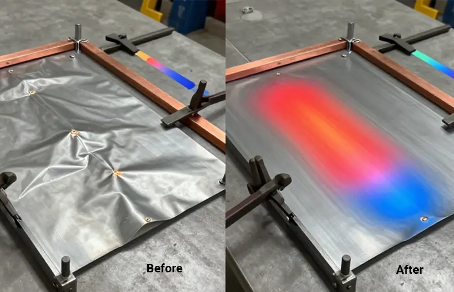
For stubborn distortion that slips through despite your best prevention efforts, controlled flame straightening offers a correction method. Heat a small spot about the size of a quarter with your torch until it glows dull red, then let it air cool naturally. Never quench with water. The cooling contraction pulls surrounding metal toward that spot, counteracting the original distortion. Practice this technique on scrap first, because heating the wrong areas makes distortion worse.
Understanding these defects and their solutions transforms frustrating failures into manageable challenges. However, many problems become preventable when you invest proper attention in what happens before and after the actual welding takes place.
Pre-Weld Preparation and Post-Weld Finishing Processes
What happens before you strike an arc often determines whether your weld succeeds or fails. The same goes for finishing work afterward. Yet these critical steps remain the most overlooked aspects of welding sheet metal fabrication. You can dial in perfect parameters and use flawless technique, but contaminated base metal in welding will still produce weak, porous joints every time.
Starting with the cleanest possible surface greatly increases the chances for a sound and strong weld. That's why proper preparation and finishing deserve as much attention as the welding itself.
Surface Preparation That Prevents Failures
Before touching your welding sheet metal project, you need a plan. According to The Fabricator, jumping into a project that seems simple often leads to costly delays, additional steps, or rework. Having a strategy helps you resist shortcuts when issues arise.
The preparation process starts with understanding what your welding method demands. Gas metal arc welding (GMAW) and gas tungsten arc welding (GTAW) typically require more preparation and a cleaner surface to produce quality welds, but also require less effort for postweld cleanup. Shielded metal arc welding allows more surface impurities but demands more interpass and postweld cleaning.
Cleaning and degreasing requirements:
- Remove all oil, grease, paint, and surface contaminants within an inch of the joint on both sides
- Use acetone or dedicated degreaser for stainless steels and aluminum alloys
- Wire brushes work effectively for rust, rubber coatings, powder coat, and paint on lighter contamination
- For heavy mill scale, use grinding wheels or flap discs, starting with less aggressive options and increasing only as necessary
Removing mill scale and oxidation:
Hot-rolled steel carries heavy mill scale that must be completely removed before welding. Flap discs are commonly used because they're easy to control, allowing you to grind, finish, and blend simultaneously. A 60-grit coated abrasive flap disc often provides sufficient aggression while leaving a better finish than coarse-grit options. Be careful with grinding wheels, as they're more aggressive and can easily remove too much base metal, putting finished parts outside specifications.
Proper fit-up and gap control:
A clean, consistent gap between pieces produces stronger, more consistent welds with less filler metal. Making your initial cuts as clean, straight, and consistent as possible reduces cleanup work later. Your choice of sheet metal welding rods or wire depends partly on how well you've controlled the gap, as larger gaps demand more filler deposition and increased heat input.
Tacking sequence strategies:
Tack welds hold pieces in alignment during final welding. On sheet metal, tacking from the center outward allows shrinkage forces to spread naturally toward the edges. Space tacks evenly along the joint length, using the minimum size needed to maintain alignment. For long seams, alternate tack placement on opposite sides of center to balance stress distribution.
Joint type selection directly impacts weld strength, aesthetics, and accessibility. According to UNIMIG, understanding various joint types is crucial to achieving desired quality in your projects:
- Butt joints: Two pieces laid parallel at roughly 180 degrees, ideal for flat surfaces and plate construction. On thin sheet metal, square butt welds often need no edge preparation
- Lap joints: Overlapping metal welded along the seam, commonly used when connecting parts with differing thicknesses or when butt joints aren't feasible
- Corner joints: Two pieces joined at 90 degrees forming an L-shape, used extensively in box, table, and frame fabrication. Closed corner joints offer higher mechanical strength but are more difficult to weld
- T-joints: Perpendicular pieces joined at right angles resembling the letter T, a type of fillet weld used across structural steel applications and manufacturing
Post-Weld Finishing for Professional Results
Once welding completes, finishing work determines whether your project looks amateur or professional. Visible welds in automotive panels, architectural metalwork, and appliance manufacturing demand show-quality appearance.
Grinding techniques:
Lower your grinding angle to maximize control and reduce gouging risk. The outside corner of a grinding wheel is most aggressive, so steep approach angles remove more material than intended. Use smooth, even strokes rather than short, choppy motions. Enter the grinding stroke on a pull rather than a push to control aggression.
Choose a type 27 (flat profile) flap disc for lower grinding angles between 5 to 10 degrees and light pressure finishing work. Type 29 (conical profile) discs work better at higher 15 to 30 degree angles for aggressive material removal.
Finishing for visible welds:
Progressive grits produce the smoothest results. Start with whatever aggression removes weld crown efficiently, then step through finer grits until you achieve the desired surface. For polished stainless steel or aluminum, this might mean progressing from 60-grit through 120, then 240, and finishing with buffing compounds.
Quality control through visual inspection:
According to Red-D-Arc, non-destructive testing methods check for defects without damaging the workpiece. Visual inspection examines welds for surface defects like porosity, undercut, and incomplete fusion. Look for consistent bead width, proper toe tie-in, and absence of cracks or surface pores.
Check for proper reinforcement without over-welding, which creates unnecessary stress concentrations and wastes material. The weld profile should appear flat to slightly convex with smooth transitions into the base metal on both sides.
For critical applications on a proper welding table top plate or dedicated fixture, dimensional accuracy matters equally to weld quality. Measure finished assemblies against specifications to verify that welding distortion hasn't pushed parts outside tolerance. Planning your welding table plans with adequate clamping provisions helps maintain dimensional control throughout the fabrication process.
With preparation and finishing processes mastered, your attention should turn to protecting yourself during the welding operation itself.
Safety Protocols and Protective Equipment Requirements
You've learned the techniques, dialed in your parameters, and mastered troubleshooting. But none of that matters if you neglect the one factor that protects your health and safety every time you strike an arc. A skilled sheet metal welder understands that proper protection isn't optional; it's the foundation that makes everything else possible.
According to OSHA regulations, employers must provide personal protective equipment when necessary to protect employees from job-related injuries, illnesses, and fatalities. OSHA's welding, cutting, and brazing standard (29 C.F.R. 1910.252) outlines specific PPE requirements for welders exposed to hazards created by these operations. This isn't just bureaucratic paperwork; it's welding 101 that keeps you working safely for decades.
Essential PPE for Every Welding Method
Every piece of metal for welding you touch creates potential hazards. The right equipment creates barriers between those hazards and your body.
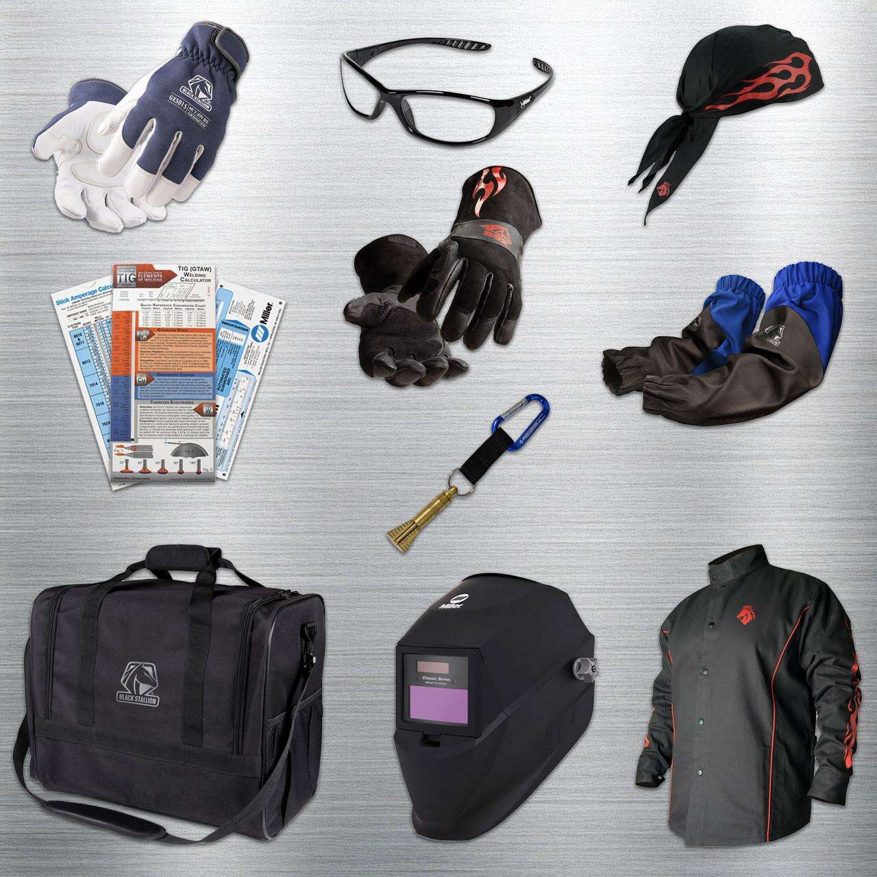
- Auto-darkening welding helmet: Look for helmets with multiple sensors (three or four) for reliable arc detection. Shade 10 is recommended for MIG welding in most shop environments. Quality matters here: cheap helmets may not darken fast enough to prevent arc eye, as experienced welders have noted when testing with low-quality equipment. Miller, Lincoln, and similar professional-grade helmets offer consistent protection with readily available replacement parts.
- Welding gloves rated for your process: TIG welding requires thinner, more dexterous gloves for precise torch control. MIG and flux-core operations demand heavier leather gloves that handle higher heat and spatter. Never use gloves with holes, worn spots, or loose seams.
- Fire-resistant clothing: Options range from flame-resistant cotton jackets to full leather or hybrid designs. Welders face constant exposure to fumes, heat, and sparks, making a welding jacket essential as all-over protection. Avoid synthetic fabrics that can melt onto skin.
- Steel-toed boots: Heavy materials, hot slag, and dropped equipment make foot protection mandatory. Leather uppers resist sparks better than synthetic materials.
- Respiratory protection: OSHA requires annual respiratory fit testing. Welding fumes are particulates requiring P100 filters, and cartridges should be changed after 30 hours of use or every six months of limited use.
Beyond personal gear, welding screens protect surrounding employees from sparks and ultraviolet rays while shielding nearby vehicles from hot slag. These screens also act as wind barriers that keep shielding gas from scattering away from the weld zone. OSHA regulation 1926.351(e) requires arc welding operations to be shielded by noncombustible screens that protect workers in the vicinity from direct arc rays.
Ventilation and Fume Hazards
The visible smoke rising from your weld puddle contains harmful metal fumes and gas by-products that demand serious attention. According to OSHA's fact sheet on welding hazards, prolonged exposure to welding fume may cause lung damage and various types of cancer, including lung, larynx, and urinary tract cancers. Health effects from certain fumes include metal fume fever, stomach ulcers, kidney damage, and nervous system damage.
Different welding methods produce varying fume levels. Flux Core Arc Welding generates the most fume, followed by Shielded Metal Arc, then Gas Metal Arc (MIG), with Tungsten Inert Gas (TIG) producing the least. However, TIG welding still presents unique hazards. Research from the Swiss National Science Foundation found that even in ventilated environments, exposure exceeded averages found in traffic-polluted air, with 15 hours of TIG welding fumes equivalent to smoking one cigarette.
UV radiation intensity also differs between processes. The arc created during TIG welding produces UV and infrared radiation that can damage the cornea and even reach the retina. Only a few seconds of unprotected exposure causes "arc eye," though symptoms may not appear for several hours. Repeated exposure has been linked to cataracts.
Material-specific fume considerations:
- Galvanized steel: Zinc coating vaporizes during welding, producing toxic zinc oxide fumes that cause metal fume fever. Powered air-purifying respirators become necessary rather than optional.
- Stainless steel: Chromium converts to hexavalent chromium (Cr(VI)) during welding, which is highly toxic and can cause cancer. OSHA's Permissible Exposure Limit is just 5 micrograms per cubic meter.
- Aluminum: Produces ozone as a constant by-product, causing chest pain, coughing, and throat irritation even at relatively low concentrations.
Ventilation requirements:
General ventilation through natural or forced air movement reduces fume and gas levels in the work area, but welding outdoors or in open spaces doesn't guarantee adequate protection. Local exhaust ventilation systems remove fumes directly from the welder's breathing zone. Position fume hoods, extractor guns, and vacuum nozzles close to the source to capture maximum contamination.
Never weld in confined spaces without proper ventilation. Shielding gases like argon and carbon dioxide displace oxygen and can lead to suffocation. OSHA defines air containing less than 19.5 percent oxygen as oxygen deficient. In enclosed areas, oxygen depletion safety alarms or personal oxygen monitors provide critical protection.
Workspace setup for safe operations:
- Position yourself upwind when welding in open or outdoor environments
- Keep exhaust ports directed away from other workers
- Remove flammable materials from the immediate welding area
- Maintain fire extinguishers within reach of the welding station
- Ensure adequate lighting for proper technique without relying solely on arc visibility
- Keep water and wet surfaces away from electrical connections to prevent shock hazards
Proper safety protocols don't slow you down; they keep you productive for years instead of sidelining you with preventable health problems. With your protective equipment in place and workspace properly configured, you're ready to make informed decisions about which welding approach best fits your specific project requirements.
Choosing the Right Welding Method for Your Project
You've learned the techniques, understood the materials, and mastered safety protocols. Now comes the decision that ties everything together: which welding method actually makes sense for your specific project? This question goes beyond technical capability. It requires balancing equipment costs, skill requirements, production demands, and quality expectations against your available resources.
The best welder for sheet metal isn't always the most expensive or most capable option. Sometimes a basic MIG setup handles the job perfectly. Other times, nothing short of precision TIG or professional outsourcing will deliver acceptable results. Let's build a framework that helps you make this decision confidently every time.
Matching Methods to Your Project Requirements
Every project brings unique constraints. Automotive body panels demand invisible welds and zero distortion. HVAC ductwork prioritizes speed and airtight seams over cosmetic perfection. Decorative architectural pieces require show-quality appearance that justifies slower processes. Structural brackets need penetration and strength above all else.
The following decision matrix matches common sheet metal applications with their optimal welding approaches:
| Application | Recommended Method | Equipment Investment | Skill Level Required | Key Considerations |
|---|---|---|---|---|
| Automotive Body Panels | TIG or MIG with pulsed settings | $1,500 - $4,000 | Intermediate to Advanced | Minimal distortion critical; visible welds unacceptable; a tig welder for thin metal excels here |
| HVAC Ductwork | MIG or Spot Welding | $500 - $2,000 | Beginner to Intermediate | Speed matters; airtight seams required; galvanized coating common |
| Decorative/Architectural | TIG | $2,000 - $5,000 | Advanced | Show-quality appearance mandatory; stainless and aluminum common |
| Structural Brackets | MIG or Flux-Core | $400 - $1,500 | Beginner to Intermediate | Penetration and strength priority; appearance secondary |
| Electrical Enclosures | Spot or MIG | $800 - $3,000 | Beginner to Intermediate | Clean interior surfaces; consistent production runs |
| Food Service Equipment | TIG | $2,500 - $6,000 | Advanced | Sanitary welds; stainless steel; no porosity acceptable |
When selecting the best welding for sheet metal applications, consider what happens after the weld. Will the joint be visible? Does it need to pass pressure testing? Will grinding and finishing hide imperfections? Your answers shape which trade-offs make sense.
A common misconception suggests that tig welding with a mig welder somehow combines benefits of both processes. In reality, these are fundamentally different techniques requiring different equipment. Multi-process machines exist that switch between MIG and TIG modes, but each mode operates independently with its own characteristics. Choose based on your primary application rather than assuming versatility solves everything.
Budget and Skill Level Considerations
Equipment costs represent just one piece of the financial puzzle. According to welding industry analysis, the true cost per linear foot of weld varies dramatically based on process selection, consumables, and labor time. Understanding these economics helps you invest wisely.
Equipment cost breakdown:
- Entry-level MIG welders: $300-$600 for hobby-grade units suitable for occasional sheet metal work
- Professional MIG equipment: $1,000-$3,000 for industrial-duty machines with pulsed capabilities
- TIG welders: $1,500-$5,000+ depending on AC/DC capability, amperage range, and features
- Spot welders: $200-$800 for portable units; $2,000+ for production-grade equipment
- Multi-process machines: $1,500-$4,000 offering MIG, TIG, and stick capabilities in one unit
Consumable cost comparison:
MIG welding consumes wire continuously, with 0.023-inch wire running approximately $40-60 per 11-pound spool. Shielding gas cylinders add ongoing expense, typically $20-40 per refill for standard 75/25 argon/CO2 mix. TIG welding uses less filler material since you control deposition manually, but tungsten electrodes require periodic replacement at $5-15 each depending on type and diameter.
Labor time considerations:
MIG welding delivers faster deposition rates, making it more economical for production work where speed directly impacts profitability. Industry research on cost per foot indicates that MIG typically costs less per linear foot than TIG when labor is factored in, despite similar consumable expenses. TIG's slower pace increases labor cost but produces superior results where appearance and precision justify the investment.
When skill gaps become costly:
Purchasing equipment beyond your current skill level leads to frustration, wasted materials, and poor results. A beginner attempting decorative TIG work on stainless steel will burn through expensive material while producing unacceptable welds. Starting with MIG on mild steel builds fundamental skills that transfer to more demanding applications later.
When to Outsource vs. Build In-House Capability
Not every welding project belongs in your shop. According to EVS Metal's contract fabrication guide, companies evaluate outsourcing versus in-house manufacturing based on several critical factors.
Contract fabrication makes sense when:
- You want to avoid large capital investments in specialized equipment
- Production volumes are variable or mid-volume (10-5,000 pieces)
- You need access to specialized capabilities like robotic welding, automated powder coating, or fiber laser cutting
- Hiring and retaining skilled fabrication staff presents ongoing challenges
- Quality certifications like ISO 9001 or industry-specific standards are required
In-house manufacturing makes sense when:
- High production volumes justify capital equipment investment
- Proprietary processes provide competitive advantage worth protecting
- Rapid iteration and immediate access to fabrication capabilities drive your business model
- You already maintain skilled welding staff with available capacity
For automotive applications requiring welded sheet metal assemblies at production volumes, working with professional manufacturing partners often delivers superior results. Companies with IATF 16949 certification, like Shaoyi (Ningbo) Metal Technology, specialize in handling complex welded sheet metal assemblies for chassis, suspension, and structural components where consistent quality and rapid turnaround matter. Their comprehensive DFM support and 5-day rapid prototyping capabilities help optimize designs before committing to mass production, which is particularly valuable when projects exceed in-house capabilities or require welding top-tier quality standards that demand specialized equipment and expertise.
The make-versus-buy decision ultimately comes down to honest assessment of your capabilities, volume requirements, and quality expectations. A fair comparison must include more than quoted piece price. In-house manufacturing carries equipment depreciation, maintenance, facilities, staffing, and utilization risk. Contract fabrication converts those fixed costs into variable costs and often proves more economical for low to mid-volume work.
Most experienced fabricators find that a welder for sheet metal projects handling 80% of their work in-house while outsourcing specialized or high-volume requirements provides optimal flexibility. This hybrid approach maintains core capabilities while accessing professional resources when projects demand them.
With your method selected and resources allocated appropriately, you're ready to apply these principles to real-world applications that demonstrate how everything comes together in practice.
Practical Applications and Next Steps for Success
Everything you've learned comes together when you apply it to real projects. Can you weld sheet metal successfully across different industries? Absolutely, but each application demands specific approaches tailored to its unique requirements. Let's walk through the most common scenarios you'll encounter and how to tackle them with confidence.
Automotive Panel and Body Work Applications
Automotive sheet metal welding represents some of the most demanding work you'll encounter. Body panels must look flawless after paint, structural repairs need to restore original crash protection, and distortion tolerance approaches zero on visible surfaces.
According to Miller Electric's automotive welding guide, vintage vehicle restoration often requires fabricating patch panels when aftermarket options aren't available. The key to successful repairs lies in proper fit-up before welding begins. Overlapping and clamping the patch accurately, scribing the trim line, then achieving a tight butt joint eliminates moisture traps that cause future rust problems.
When welding thin sheet metal on automotive panels, tack spacing matters critically. Professional body welders space tacks no more than one inch apart, then stitch the joint closed by adding new tacks at the end of each previous one. This skip welding approach allows the panel to cool completely before adding more welds, dramatically reducing distortion that would otherwise ruin hours of careful metalwork.
Key techniques for automotive work:
- Use butt joints rather than lap joints to maintain consistent panel thickness and prevent moisture collection
- Keep wire stickout around 1/2 inch for MIG welding to control heat input precisely
- Remove weld bulk with a 36-grit disc grinder, working carefully to prevent additional heat distortion
- Raise low spots with hammer and dolly work before final sanding with 50-grit, then finish with 120-grit orbital sanding
- For tig sheet metal work on curved panels, weld in a single pass from end to end; flat panels benefit from 1-inch segments with skipping to different areas
TIG welding offers significant advantages for visible automotive work. The bead can remain very small, ideally no more than 1-1/2 times material thickness, and the soft welds respond well to hammer and dolly shaping afterward. This allows you to smooth distortion without grinding away all your carefully deposited filler metal.
Industrial Enclosures and HVAC Fabrication
Industrial applications prioritize different qualities than automotive work. Speed, consistency, and airtight integrity often matter more than show-quality appearance. Understanding these priorities helps you mig weld sheet metal efficiently without over-engineering your approach.
HVAC ductwork fabrication demands attention to several critical factors. According to industry fabrication guides, precision fabrication determines system performance, energy efficiency, and overall project cost. Duct wall thickness follows SMACNA standards based on pressure class and duct dimensions, not guesswork. Cross-reference your system's pressure specifications with published tables to determine minimum gauge requirements.
For ductwork applications, sheet metal welds primarily appear at transverse connections joining duct sections and longitudinal seams running the length of each piece. Robotic welding increasingly handles stainless steel ductwork for demanding environments, offering consistent quality, reduced distortion through precise heat control, and higher productivity than manual methods.
- Sealing requirements: Any mechanical connection can become a pathway for air loss; mastic sealants rated for system temperature and compatible with insulation materials provide long-term performance
- Reinforcement needs: Large duct panels require stiffeners to prevent bulging, vibrating, and producing noise under pressure; SMACNA standards specify exact stiffener types, sizes, and spacing
- Material selection: Galvanized steel handles most standard applications; stainless steel serves corrosive or high-temperature environments; aluminum reduces weight but requires attention to lower structural strength
Electrical enclosure fabrication combines welding with other sheet metal processes for complete assemblies. Manufacturing engineers review designs for manufacturability before production begins, ensuring parts can be bent, welded, and assembled efficiently. According to fabrication industry guidance, design for manufacturability (DFM) reviews catch excessive forming, missing critical dimensions, and tolerance issues that create problems during production.
Standard tolerances for sheet metal fabrication account for material thickness variation, machine capabilities, and cumulative effects across multiple operations. Hole-to-bend tolerances typically require +/-0.010 inch to accommodate natural variation in material, punching processes, and press brake positioning. Tighter tolerances increase costs and reduce productivity without necessarily improving function.
Decorative architectural metalwork occupies the opposite end of the quality spectrum from industrial work. Every sheet metal weld remains visible, demanding TIG welding skill and post-weld finishing that transforms raw joints into seamless surfaces. Stainless steel and aluminum dominate this segment, requiring precise heat control to prevent discoloration and maintain material properties.
Key Takeaways by Application Type
Before you tackle your next project, review these organized summaries that capture essential guidance for each major application category:
Automotive body and panel work:
- Prioritize distortion control above all else; visible warping ruins otherwise perfect welds
- Use butt joints with careful fit-up to eliminate future rust traps
- Space tacks closely and allow cooling between weld passes
- TIG welding produces workable beads that respond to hammer and dolly shaping
- Progressive grinding and sanding from coarse to fine produces paint-ready surfaces
HVAC ductwork and industrial applications:
- Follow SMACNA standards for gauge selection and reinforcement requirements
- Seal all connections with appropriate mastic compounds
- Consider spot welding for production efficiency on overlapping seams
- Address galvanized material safely with proper ventilation and respiratory protection
- Air leakage testing validates fabrication quality on completed assemblies
Electrical enclosures and precision assemblies:
- Design for manufacturability before committing to production
- Account for tolerance stack-up across multiple bends and features
- Clean interior surfaces matter for electronics and food service applications
- Spot welding delivers Class A finishes without grinding on appropriate thicknesses
- Consider when welding combines with stamping and forming for optimal results
Decorative and architectural metalwork:
- TIG welding provides the control needed for show-quality appearance
- Material selection impacts both aesthetics and long-term durability
- Post-weld finishing often determines project success more than the welding itself
- Budget adequate time for progressive polishing on visible stainless and aluminum
Combining Welding with Other Fabrication Methods
Many projects require metal and welding to work alongside stamping, forming, bending, and finishing operations. Complete assemblies rarely emerge from welding alone. Understanding when these processes integrate helps you plan projects more effectively.
Stamped components often require welding for final assembly. Automotive chassis parts, for example, combine precision stamped brackets with welded connections that join subassemblies into structural units. This integration demands careful attention to tolerance management, since stamping introduces its own dimensional variation that accumulates when welded assemblies must fit together precisely.
For manufacturers requiring welded sheet metal components at production volumes, partnering with fabricators offering comprehensive DFM support proves invaluable. Companies like Shaoyi (Ningbo) Metal Technology provide rapid prototyping that helps optimize designs before committing to mass production. This approach catches tolerance issues, identifies process improvements, and validates that stamping, forming, and welding operations work together seamlessly. Their 12-hour quote turnaround accelerates decision-making when evaluating whether projects fit in-house capabilities or benefit from professional manufacturing solutions.
Whether you're tackling automotive restoration, industrial fabrication, or decorative metalwork, success comes from matching your approach to project requirements. The techniques, parameters, and troubleshooting strategies covered throughout this guide provide the foundation. Your next step? Pick up your torch, dial in your settings, and start building the skills that transform raw sheet metal into precision assemblies.
Frequently Asked Questions About Welding Sheet Metal Fabrication
1. What type of welding is used for sheet metal?
MIG and TIG welding are the most common methods for sheet metal. MIG welding offers faster speeds and easier learning, making it ideal for automotive panels, HVAC ductwork, and general fabrication. TIG welding provides superior precision and aesthetics for thin materials down to 0.005 inches, preferred in aerospace, medical, and decorative applications. Spot welding excels in production environments for overlapping panels between 0.020 to 0.090 inches thick, delivering Class A finishes without grinding.
2. Is TIG or MIG better for sheet metal?
Both methods work excellently on sheet metal, but serve different purposes. MIG welding delivers faster deposition rates with a shorter learning curve, making it cost-effective for production work. TIG welding sacrifices speed for superior control, producing cleaner beads with virtually no spatter, ideal when appearance matters. For visible automotive panels or decorative stainless steel, TIG typically wins. For HVAC ductwork or structural brackets where speed matters, MIG proves more practical.
3. What settings should I use for MIG welding thin sheet metal?
For thin sheet metal MIG welding, use approximately 1 amp per 0.001 inch of material thickness as a starting point. For 18-gauge steel (0.048 inches), start around 45-65 amps with 16-18 volts and 0.023-inch wire. Use 75% argon/25% CO2 shielding gas at 18-22 CFH. Keep wire stickout around 1/2 inch and travel quickly enough to prevent burn-through while maintaining fusion. These are baseline settings requiring adjustment for your specific equipment and conditions.
4. How do I prevent burn-through when welding sheet metal?
Burn-through prevention requires controlling heat input through multiple strategies. Reduce amperage and voltage settings, increase travel speed, and use skip welding patterns that allow cooling between welds. Install copper or aluminum backing plates that pull heat away from the weld zone. Switch to smaller diameter wire (0.023-inch) for better heat control. For extremely thin materials, consider TIG welding with pulsed settings. If burn-through occurs, attach a backing plate, fill the hole with reduced settings, then grind flush and re-weld.
5. When should I outsource sheet metal welding versus doing it in-house?
Outsource when you need specialized equipment like robotic welding, require quality certifications such as IATF 16949, have variable or mid-volume production (10-5,000 pieces), or lack skilled welding staff. In-house manufacturing makes sense for high production volumes justifying equipment investment, proprietary processes requiring protection, or when rapid iteration drives your business model. Many fabricators handle 80% in-house while outsourcing specialized or high-volume work to certified manufacturers offering DFM support and rapid prototyping.