 Küçük partiler, yüksek standartlar. Hızlı prototip hizmetimiz doğrulamayı daha hızlı ve kolay hale getirir —

Kalıp Presi Kalıbı Sırları: Çelik Seçiminden ROI Uzmanlığına

Kalıp Pres Kalıbı Nedir ve Nasıl Çalışır?
Aracınızın, ev aletlerinizin veya akıllı telefonunuzun içinde bulunan hassas parçaları üreten üreticilerin düz metal levhaları nasıl bu kadar kesin bileşenlere dönüştürdüğünü hiç merak ettiniz mi? Cevap, bir "kalıp pres kalıbı" adı verilen özel bir araçta gizlidir—bir özel olarak mühendislikle tasarlanmış cihaz ki bu cihaz, kontrollü kuvvet uygulaması yoluyla levha metalini şekillendirir.
Peki, kalıp pres kalıbı tam olarak nedir? Bu, bir kalıp presine yerleştirilen, levha metalini kesen, bükerek ya da şekillendirerek belirli formlara getiren bir hassas kalıp takımıdır. Bunu, çok gelişmiş bir kurabiye kesme kalıbı gibi düşünebilirsiniz; ancak burada hamur yerine çelik, alüminyum, bakır ve diğer metallere işlem uygulanır. Pres kapatıldığında, büyük bir basınç malzemenin iki tam olarak eşleşen yarısının arasına uygulanır ve bu sayede dikkat çekici düzeyde doğruluk ve tutarlılıkla parçalar oluşturulur.
Metal presleme işleminin ne olduğunu anlamak, bu temel kavramla başlar: kalıp, işlenmiş parçanın tüm özelliklerini belirler. Boyutsal doğruluktan yüzey pürüzlülüğüne kadar, nihai bileşenin her özelliği, kalıp tasarımı ve yapısına dayanır. Bir bileşende yalnızca birkaç mikrometrelik küçük bir hata, sorunların zincirleme oluşmasına neden olabilir—yanlış parça boyutları, erken takım aşınması, pahalı duruş süreleri ve yüksek hurda oranları.
Bir Pres Kalıbının Anatomisi
İmalat terimleriyle bir kalıp nedir? Aslında her bir bileşeni kritik bir rol üstlenen karmaşık bir montajdır. İmalatta kalıpların ne olduğunu sorduğunuzda, aslında mükemmel uyum içinde çalışan hassas mühendislikle üretilmiş bir tamamlayıcı parça sistemi hakkında soru soruyorsunuz.
Bir pres kalıbını oluşturan temel bileşenler şunlardır:
- Zımba: İş parçasına giren veya üzerine baskı uygulayan erkek bileşen. Sertleştirilmiş takım çeliğinden veya karbürden yapılmıştır ve gerçek kesme, delme veya şekillendirme işlemlerini gerçekleştirir.
- Kalıp Bloğu (Die Button): Deliciye karşılık gelen dişi parça. Bu hassas olarak taşlanmış bileşen, deliciyi alan boşluğu veya açıklığı içerir ve temiz kesimler için dikkatle hesaplanmış toleranslara sahiptir.
- Çıkarıcı plaka: Delici malzemeyi delmeden sonra metalin doğal elastikiyeti nedeniyle deliciyi sıkıca kavrar. Soyma plakasının görevi, delici geri çekildiğinde bu malzemeyi deliciden ayırmaktır.
- Kılavuz Pimleri ve Burçlar: Bu sertleştirilmiş, hassas olarak taşlanmış bileşenler, üst ve alt kalıp yarısının mükemmel hizalanmasını sağlar. Bunlar, milyonlarca çevrim boyunca tüm parçaların doğru şekilde hareket etmesini sağlayan eklemlerdir.
- Kalıp Tabanları: Kalıp setinin üst ve alt kısmını oluşturan ağır taban plakaları. Alt taban (shoe), presin tabanına monte edilirken üst taban (shoe), presin ram’ine bağlanır.
- Destek Plakaları: Delicilerin ve kalıp bloklarının (die buttons) arkasına yerleştirilen, kuvveti dağıtmak ve daha yumuşak kalıp tabanlarına (shoes) zarar vermemek amacıyla sertleştirilmiş plakalar.
Kalıpların Ham Metalin Hassas Parçalara Dönüşümüne Katkı Sağlaması
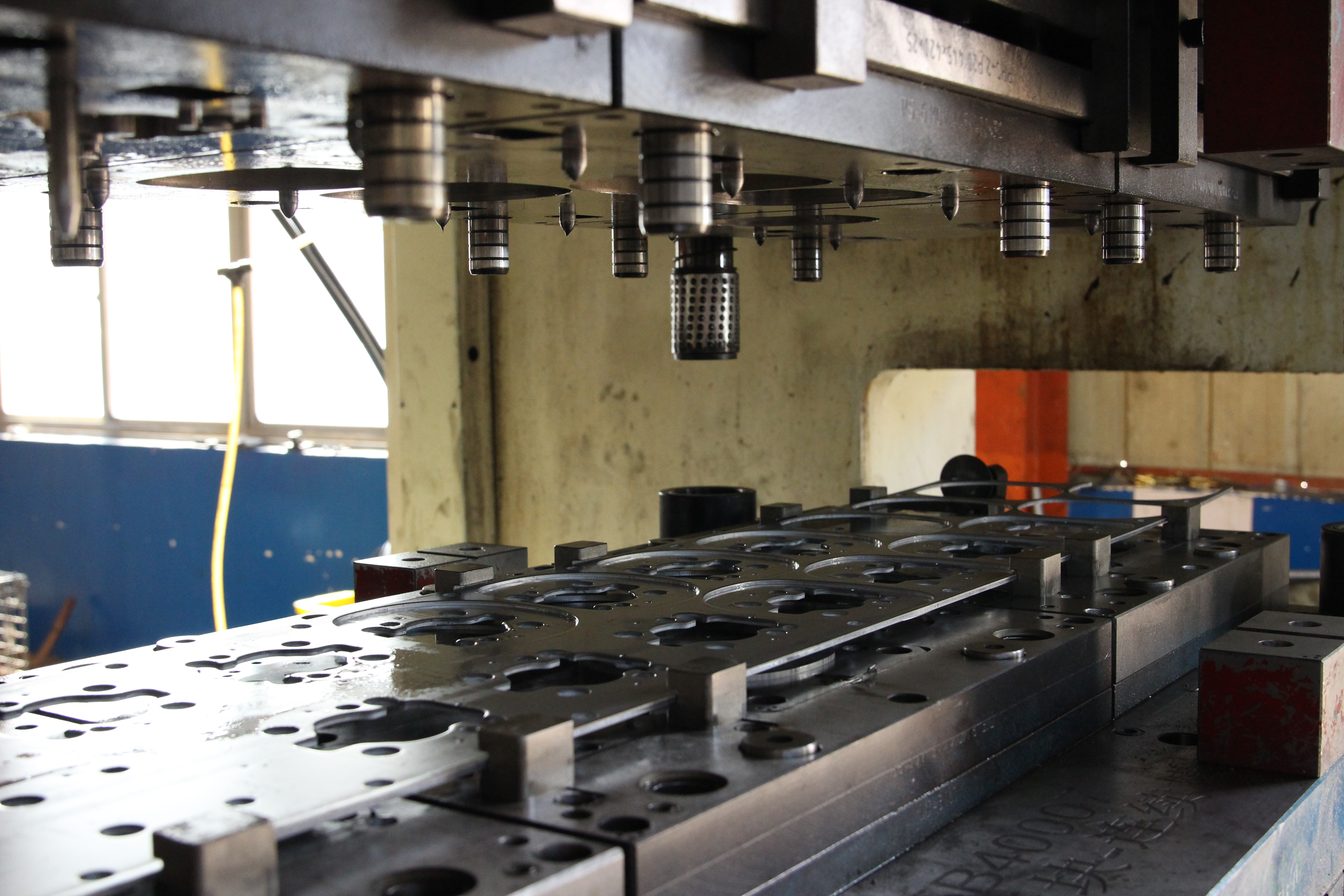
Dövme işlemi temelde nedir? Bu, büyük bir kuvvetin tam olarak kontrol edilen bir şekilde uygulanmasıdır. Pres ve kalıp, bitmiş parçaları oluşturmak için şu şekilde birlikte çalışır:
Bu süreç, genellikle bir bobinden veya önceden kesilmiş saclar halinde beslenen sac metalin iki kalıp yarısının arasına girmesiyle başlar. Pres devreye girdiğinde, üst kalıp tablasını aşağı doğru devasa bir kuvvetle hareket ettirir; bu kuvvet bazen yüzlerce tondan fazla olabilir. Çekici (punch), malzemeyle temas ettiğinde onu ya keser (boşaltma veya delme işlemlerinde), belirli bir açıda bükerek şekillendirir ya da üç boyutlu bir forma çekerek şekillendirir.
Kalıp tasarımı ile nihai parça kalitesi arasındaki ilişki yadsınamaz derecededir. Pres işlemleri için kullanılan bir kalıp, malzeme kalınlığını, metal türünü, gerekli toleransları ve üretim hacmini dikkate almalıdır. Çekici ile kalıp arasındaki açıklık—genellikle malzeme kalınlığının bir yüzdesi olarak belirlenir—kenar kalitesini, kenar kıvrımını (burr) ve takım ömrünü doğrudan etkiler.
Uygun kalıp tasarımı olmadan bir sac kesme işlemi nedir? Basitçe söylemek gerekirse, bu durum tutarsız parçalar ve sık arızalanan kalıplar için bir reçetedir. Çağdaş üreticiler, ilk tasarımları geliştirmek için CAD yazılımı kullanır; böylece herhangi bir metal kesilmeden önce tüm bileşenlerin doğru çalıştığından emin olurlar. Bu başlangıçta yapılan mühendislik yatırımı, hurda oranlarının azaltılması, kalıpların ömrünün uzatılması ve milyonlarca üretim döngüsü boyunca parça kalitesinin tutarlı kalması yoluyla karşılığını verir.

Sac Kesme Kalıplarının Türleri ve Mekanik İlkeleri
Sac kesme pres kalıbının temel bileşenlerini artık anladığınıza göre, muhtemelen şu soruyu sormaktasınız: Projem için hangi tür kalıbı kullanmalıyım? Cevap, üretim hacminize, parça karmaşıklığınıza ve bütçe kısıtlarınıza bağlıdır. Şimdi, sac kesme kalıplarının dört ana kategorisini ve her birinin belirli uygulamalara özel olarak uygun hale gelmesini sağlayan mekanik ilkeleri inceleyelim.
Sürekli Yüksek Hızlı Üretim İçin İlerlemeli Kalıplar
Ham madde olarak levha metalin bir uçtan girdiği ve bitmiş parçaların diğer uçtan çıktığı bir üretim hattını hayal edin—bütün bu süreç tek bir kalıp seti içinde gerçekleşir. İşte bu, ilerlemeli kalıp ve presleme teknolojisinin gücüdür .
İlerlemeli kalıplar, metal şeridin presin içinden ilerlediği sırayla düzenlenmiş çoklu istasyonlardan oluşur; her istasyon, şeridin ilerlemesiyle birlikte belirli bir işlemi gerçekleştirir. Her pres strokuyla şerit sabit bir mesafe (adım adı verilir) ileriye doğru hareket eder ve farklı istasyonlar aynı anda kesme, delme, şekillendirme ve bükme gibi işlemleri gerçekleştirir. Şerit son istasyona ulaştığında, tamamlanmış parça taşıyıcı şeritten ayrılmış olur.
Bu konfigürasyonu bu kadar verimli kılan nedir? Mekanik ilke basittir: Bireysel parçaları ayrı işlemlerle işlemek yerine, ilerleyici kalıp ve dövme sistemleri tüm şekillendirme adımlarını tek bir sürekli süreçte tamamlar. Tek bir pres darbesiyle birinci istasyonda delikler açılır, ikinci istasyonda büküm oluşturulur, üçüncü istasyonda kabartma özelliği eklenir ve dördüncü istasyonda aynı şeridin farklı kısımlarında aynı anda bitmiş parça kesilir.
Bu yaklaşım, yüksek hacimli üretimler için olağanüstü verimlilik sağlar. İlerleyici kalıplar, otomotiv imalatı, elektronik üretimi ve ev aletleri üretimi gibi alanlarda işçilerinin temel taşları olarak kabul edilir ve saatte binlerce parça üretirken dikkat çekici ölçüde tutarlılık gösterir. Ancak bu sistemler önemli bir başlangıç yatırımı ve mühendislik uzmanlığı gerektirir.
Transfer, Bileşik ve Kombinasyon Kalıp Konfigürasyonları
Her uygulama ilerleyici kalıp modeline uygun değildir. Bazen parçalar çok büyük, çok karmaşık olur veya ilerleyici kalıplamanın maliyetini haklı çıkarmayacak kadar düşük hacimlerde üretilirler. İşte burada taşıma kalıpları, bileşik kalıplar ve kombinasyon kalıpları devreye girer.
Taşıma matları çok istasyonlu şekillendirme işlemine farklı bir yaklaşım sunarlar. Parçaları taşıyıcı şeride bağlı tutmak yerine, taşıma sistemleri mekanik parmaklar veya tutucular kullanarak tek tek iş parçalarını istasyonlar arasında taşır. Bu yapı, parça geometrisi nedeniyle şerit tabanlı ilerlemenin uygulanamadığı daha büyük ve daha karmaşık parçaların — örneğin otomotiv gövde panelleri veya yapısal bileşenler — üretiminde üstün performans gösterir.
Buradaki mekanik avantaj esnekliktir. Her istasyon bağımsız olarak çalışır ve taşıma mekanizması işlemler arasında parçaları döndürebilir, çevirebilir veya yeniden konumlandırabilir. Taşıma teknolojisi kullanan kalıplar ve presleme operasyonları, ilerleyici sistemlerde üretimi imkânsız olan parçaları işleyebilir; ancak bunu biraz daha düşük hızlarda gerçekleştirir.
Bileşik kalıplar tam tersi yaklaşımı benimser: tek bir istasyonda, tek bir darbeyle birden fazla işlemi aynı anda tamamlar. Bileşik kalıp ile yapılan dövme işlemi, iç delikleri delerken aynı anda dış konturu da keser. Bu, parçalar arasındaki mükemmel eşmerkezliliği sağlar—somunlar, conta ve elektrik bağlantı elemanları gibi hassas bileşenler için kritik bir gereksinimdir.
Mekanik prensip, pres darbesi sırasında çoklu kesme kenarlarının malzemeye sırayla etki etmesini sağlayan dikkatle tasarlanmış boşluklar ve yaylı bileşenlere dayanır. Bileşik kalıplar yalnızca kesme işlemlerine (şekillendirme işlemine değil) sınırlı olsa da, üstün kenar kalitesine sahip ve son derece düz parçalar üretir.
Kombinasyon Kalıpları bileşik kalıpların yeteneklerini şekillendirme operasyonlarıyla birleştirir. Tek bir vuruşta bu sac metal pres kalıpları, bir şekli kesip çıkartabilir (blanking), delikler açabilir ve bir büküm oluşturabilir — hepsi tek bir istasyonda gerçekleşir. Bu kalıplar, progresif kalıp yatırımı maliyet açısından haklı çıkmadığı durumlarda orta hacimli üretimde orta düzeyde karmaşık parçalar için idealdir.
Kalıp Türlerinin Karşılaştırılması: Operasyon, Uygulama ve Yatırım
Doğru kalıp türünü seçmek, birden fazla faktörü dengelemeyi gerektirir. Aşağıdaki karşılaştırma, her yapılandırmanın farklı imalat gereksinimlerini nasıl karşıladığını göstermektedir:
| Die türü | İşlem yöntemi | İdeal Parça Karmaşıklığı | Hacim Uygunluğu | Tipik Sektörler | Göreceli Kalıp Maliyeti |
|---|---|---|---|---|---|
| Ilerleme damacı | Sürekli şerit üzerinde ardışık istasyonlar; parça her vuruşta ilerler | Birden fazla özelliğe sahip küçük ve orta boy parçalar | Yüksek hacimli üretim (yılda 100.000+) | Otomotiv, elektronik, ev aletleri, donanım | Yüksek ($50.000–$500.000+) |
| Transfer Kalıp | Mekanik taşıma sistemi, bağımsız istasyonlar arasında bireysel parçaları taşır | Yeniden konumlandırma gerektiren büyük ve karmaşık parçalar | Orta ila yüksek hacim | Otomotiv karoser parçaları, havacılık, ağır ekipman | Yüksek ($75.000–$750.000+) |
| Bileşik kalıp | Birden fazla kesme işlemi tek darbede aynı anda gerçekleştirilir | Kesin özellik hizalaması gerektiren düz parçalar | Orta ila yüksek hacim | Elektronik ürünleri, tıbbi cihazlar, hassas donanım | Orta düzey ($15.000–$100.000) |
| Kombine Kalıp | Tek istasyonda birleştirilmiş kesme ve şekillendirme işlemleri | Şekillendirme gereksinimleri olan orta karmaşıklıkta parçalar | Düşük ila orta hacim | Tüketici ürünleri, genel imalat | Orta düzey ($20.000–$150.000) |
Bu tip kalıp türlerini anlamak, kalıp yatırımlarınızı üretim gereksinimlerine uygun hale getirmenize yardımcı olur. Yüksek kalıp maliyetlerinin milyonlarca parça üzerinden amorti edilmesi gerektiğinde ilerleme (progressive) kalıbı mantıklı bir seçenektir; buna karşılık kombinasyon kalıpları, daha kısa üretim miktarlarında ve kalıp ekonomisinin daha basit çözümleri tercih ettiği durumlarda esneklik sağlar.
Seçim ayrıca malzeme verimi, çevrim süresi ve bakım gereksinimleri gibi ikincil faktörleri de etkiler. İlerleme kalıpları genellikle optimize edilmiş yerleştirme (nesting) sayesinde daha yüksek malzeme verimi sağlarken, transfer kalıpları bakım ve parça kontrolü açısından üretim süreçleri sırasında daha kolay erişim imkânı sunar.
Kalıp türleri ile bunların mekanik ilkeleri konusunda net bir anlayışa sahip olduktan sonra, bir sonraki kritik karar, kalıp yapımında kullanılacak doğru malzemelerin seçilmesidir; bu seçim, doğrudan takım ömrünü, parça kalitesini ve uzun vadeli mali performansı etkiler.
Kalıp Malzemeleri ve Takım Çeliği Seçim Kriterleri
Kalıp tipinizi seçtiniz—şimdi, kalıplarınızın 100.000 döngü mü yoksa 10 milyon döngü mü dayanacağını belirleyecek bir karar verme aşamasındasınız. Kalıp ve takımların imalatında kullanılan malzemeler, aşınmaya dirençlilik, boyutsal kararlılık ve sonuç olarak parça başına maliyetinizi doğrudan etkiler. Yanlış seçim yapmak, sık sık bilenme gereksinimi, tutarsız parçalar ve pahalı üretim duruşlarına yol açar. Akıllıca seçim yapmak ise çelik malzemenizin... şileme kalıplarınızı uzun vadeli üretim varlıkları haline getirir .
Peki, metal şekillendirme kalıpları gibi talepkâr bir iş için bazı malzemeleri doğru kılan nedir? Bu, sertlik, tokluk, aşınmaya dirençlilik ve işlenebilirlik arasında dikkatli bir denge kurulmasına bağlıdır. Şimdi profesyonel kalıp üreticilerinin güvenilirliği olan özel çelik sınıflarını ve ısıl işlemlerini inceleyelim.
Takım Çelikleri Sınıfları ve Performans Özellikleri
Kalıp ve takım imalatı hizmetleri genellikle üç ana takım çeliği ailesiyle çalışır; her biri belirli çalışma koşulları ve performans gereksinimleri için tasarlanmıştır.
D Serisi (Soğuk İş Takım Çelikleri) dövme kalıbı yapımının temel malzemelerini temsil eder. Yaklaşık %12 krom içeren D2 çeliği, mikroyapısında yaygın olarak dağılmış yüksek miktardaki krom karbürleri sayesinde olağanüstü aşınmaya dayanıklılık sağlar. Bu karbürler, sac metalin kalıp yüzeyleri üzerinde milyonlarca kez kaydığı sırada meydana gelen aşındırıcı aşınmaya karşı gömülü zırh gibi davranır. D2, uygun ısıl işlem sonrası genellikle 58-62 HRC sertlik seviyesine ulaşır; bu nedenle kenar tutma özelliği kritik öneme sahip olduğu kesme kalıpları, delme punch’ları ve yüksek hacimli üretim kalıpları için idealdir.
A Serisi (Hava ile Sertleşen Kalıp Çelikleri) uygulamanız hem aşınmaya dayanıklılık hem de tokluk gerektirdiğinde dengeli bir yaklaşım sunar. 57-62 HRC sertliğine kadar ısıl işlem görmüş A2 çeliği, ısı işlemi sırasında mükemmel boyutsal kararlılık sağlar; bu da dar toleransların önemli olduğu durumlarda kritik bir faktördür. A2, yağ veya su verme gibi işlemler gerektirmeden havada üniform olarak sertleştiği için işleme sırasında daha az şekil bozulması gösterir. Bu nedenle, karmaşık geometrilere sahip sac kalıpları veya kritik boyutsal gereksinimleri olan kalıplar için tercih edilen bir malzemedir.
S Serisi (Darbe Dirençli Kalıp Çelikleri) en yüksek sertliği değil, tokluğu önceliklendirir. Genellikle 54-58 HRC sertliğine kadar ısıl işlem görmüş S7 çeliği, daha sert ve kırılgan sınıfları çatlatabilecek darbe enerjisini emer. Kalıp üretiminiz ağır kesme (blanking) operasyonları, kalın malzemeler veya darbeli yükleme koşulları içerdiğinde S7, üretim hatlarını durdurabilecek ve pahalı pres ekipmanlarına zarar verebilecek felaket niteliğinde kalıp arızalarını önler.
| Malzeme Türü | Sertlik Aralığı (HRC) | En İyi Uygulamalar | Aşınma Özellikleri |
|---|---|---|---|
| D2 Kesici Çelik | 58-62 | Kesme kalıpları, delme punch’ları, yüksek hacimli üretim | Mükemmel aşındırıcı aşınma direnci; yüksek karbür içeriği |
| A2 Takım Çeliği | 57-62 | Karmaşık kalıp geometrileri, hassas şekillendirme, dar toleranslar | İyi aşınma direnci ile üstün boyutsal stabilite |
| S7 takım çeliği | 54-58 | Ağır kesme işlemlerinde, kalın malzemelerde ve darbeye eğilimli işlemlerde | Orta düzey aşınma direnci; üstün darbe emilimi |
| Gri Demir | 45-52 | Büyük kalıp gövdeleri, yapısal bileşenler, titreşim sönümleme | Daha düşük aşınma direnci; aşınmaya maruz kalmayan yüzeyler için maliyet etkin |
| Düktil dökme demir | 50-55 | Kalıp tabanları, daha yüksek dayanım gerektiren yapısal elemanlar | Dökme demire göre geliştirilmiş tokluk; iyi işlenebilirlik |
| Tungsten Karbür | 70-75 | Kritik kesici kenarlar, yüksek aşınmaya maruz tutulan pimler, aşındırıcı malzemeler | Üstün aşınma direnci; takım çeliğine kıyasla 10–20 kat daha uzun ömür |
Kalıp Ömrünü Uzatan Karbür Bileşenler
Standart takımlar, üretim sürecinize gereken dayanıklılığı sağlayamadığında tungsten karbür gömülü parçalar çözüm haline gelir. Bu süper sert bileşenler (70–75 HRC’ye ulaşan), yüksek aşınma yükü altında çalışan uygulamalarda geleneksel takım çeliğine kıyasla 10 ila 20 kat daha uzun ömürlüdür.
Karbür gömülü parçalar, bu pahalı malzemeden tamamı karbürden üretilmiş kalıplar yerine stratejik olarak kritik kesme kenarlarına ve yüksek aşınma maruz kalan temas noktalarına yerleştirilir. Bu hibrit yaklaşım—aşınmaya eğilimli bölgelerde karbür gömülü parçalarla desteklenmiş takım çeliği kalıp gövdeleri—performans ile ekonomiyi dengeler. Karbürün yaygın kullanım alanları arasında ilerlemeli kalıplarda delme uçları, paslanmaz çelik gibi aşındırıcı malzemelerin kesildiği boşaltma kenarları ve aşırı kaymalı temas altında çalışan şekillendirme bölgeleri yer alır.
Takas nedir? Karbürün aşırı sertliği, artan kırılganlıkla birlikte gelir. Şoku emen S7 takım çeliğinin aksine, karbür darbe yüklemesi altında çatlayabilir veya kırılabilir. Doğru kalıp tasarımı, bu sınırlamayı göz önünde bulundurarak karbür bileşenlerinin çekme veya darbe kuvvetleri yerine basınç kuvvetleriyle karşılaşmasını sağlar.
Kalıp Ömrünü Katlanarak Uzatan Yüzey İşlemleri
Temel malzeme seçiminin ötesinde, yüzey işlemler ve kaplamalar takım performansını önemli ölçüde uzatır. Bu işlemler, kalıbın yüzeyini kendisini değiştirerek ya da sürtünmeyi azaltan ve aşınmaya direnen koruyucu katmanlar uygulayarak çalışır.
İyon Nitrürleme geleneksel krom kaplamadan uzaklaşan bir geçişi temsil eder. Bu işlem, yaklaşık 950 °F’de çelik yüzeyine azot difüze eder ve krom gibi alaşım elementleriyle bileşikler oluşturarak metalurjik bir bağ oluşturur. 58 HRC’yi aşan aşırı sertlik ve üstün aşınma ile yorulma direnci sertleştirilmiş kabuk derinliği, uygulama gereksinimlerine bağlı olarak 0,0006 ila 0,0035 inç arasındadır. Krom kaplamaya özgü yüzey bağının aksine, bu difüzyon tabanlı işlem, daha dayanıklı bir sertleştirilmiş katman oluşturur ve aynı zamanda sonraki cilalama ve yüzey işlemenin yapılmasına olanak tanır.
Fiziksel Buhar Biriktirme (PVD) bu kaplamalar, genellikle yaklaşık 750 °F’lik nispeten düşük sıcaklıklarda, 1–4 mikron kalınlığında krom nitrür (CrN) ince filmler uygular. Bu kaplamalar, kimyasal ve ısıya dayanıklılık sağlar; yüzey sertliğini artırır; sürtünmeyi azaltan ve yaklaşık 0,5 değerinde düşük sürtünme katsayısı sunar. Düşük işlem sıcaklığı, doğru şekilde ısıl işlem görmüş alt tabakalarda parça distorsiyonunu en aza indirir.
Malzeme Seçimi Kararlarını Etkileyen Faktörler
Kalıp kalıplarınız için en uygun malzemeleri seçmek, birbirleriyle ilişkili çok sayıda faktörü dikkate almayı gerektirir:
- Üretim Hacmi: Daha yüksek üretim hacimleri, kalıbın ömrü boyunca parça başı kalıp maliyetlerini düşüren, yüksek kaliteli malzemelerin ve işlemlerin kullanımını haklı çıkarır.
- İş parçası malzemesi: Paslanmaz çelik veya yüksek mukavemetli alaşımlar gibi aşındırıcı malzemeler, üstün aşınma direncine sahip daha sert kalıp malzemeleri gerektirir.
- Parça Toleransı Gereksinimleri: Dar boyutsal özellikler, A2 gibi mükemmel ısı işlem kararlılığına sahip malzemeleri tercih eder.
- İşlem Türü: Ağır kesme işlemlerinde darbe dirençli sınıf malzemeler gerekir; hassas kesim ise maksimum sertlikten yararlanır.
- Bakım Kapasitesi: Daha sert malzemeler kenarları daha uzun süre korur ancak yeniden bileme işlemi için özel taşlama ekipmanları gerektirir.
- Bütçe kısıtlamaları: Başlangıçtaki malzeme maliyetleri, bakım ve yenileme dahil olmak üzere toplam yaşam döngüsü maliyetleriyle dengelenmelidir.
Doğru malzeme seçimi her zaman en sert ya da en pahalı seçenek değildir; bunun yerine, belirli uygulamanız için optimum performansı sunarken toplam sahiplik maliyetini en aza indiren seçenektir.
Kalıp malzemeleri seçildikten sonra bir sonraki kritik husus, kalıplarınızın ve onu çalıştıracak pres ekipmanınızın birbiriyle uyumlu olduğundan emin olmaktır. Farklı pres teknolojileri, kalıp tasarımı ve malzeme seçimi üzerinde farklı gereksinimler oluşturur.

Pres Türleri ve Kalıp Uyumluluk Gereksinimleri
Kalıp türünüzü ve malzemelerinizi seçtiniz—ancak birçok üretici tarafından göz ardı edilen bir soru şu: Presiniz, bu kalıplarla gerçekten en iyi performansı sağlayacak mı? Kalıp pres makineniz ile çalıştırdığınız kalıplar arasındaki ilişki, yalnızca tonaj değerlerini eşleştirmekten çok daha ince ayrıntılıdır. Farklı pres teknolojileri, kalıp tasarımına farklı talepler getirir; parçaların kalitesini benzersiz şekillerde etkiler ve karmaşık şekillendirme işlemlerine yönelik olanakları (ya da sınırlamaları) belirler.
Bu etkileşimleri anlayarak, pahalı uyumsuzluklardan kaçınabilir ve farkında bile olmayabileceğiniz performans özelliklerini ortaya çıkarabilirsiniz. Mekanik, hidrolik ve servo preslerin, presleme ve kalıplama uygulamalarında her birinin sunduğu farklı güçlü yönleri birlikte inceleyelim.
Pres Yeteneklerini Kalıp Gereksinimlerine Uydurma
Her sac levha presleme işlemi, pres özellikler ile kalıp gereksinimleri arasındaki dikkatli bir hizalamayı gerektirir. Bu uyumluluk denklemini belirleyen üç temel faktör vardır: tonaj, strok profili ve hız.
Tonaj Gereksinimleri presleme işleminizi tamamlamak için gereken kuvveti temsil eder. Bu değerin doğru şekilde hesaplanması, malzeme türü, kalınlığı, parça çevresi ve işlem türünü içerir. Tonajın yetersiz belirlenmesi, eksik şekillendirme ve kalıbın erken aşınmasına neden olur. Tonajın fazla belirlenmesi ise gereğinden fazla pres kapasitesi için sermaye kaybına yol açar. 200 tonluk işlemler için tasarlanmış bir pres kalıbı, 150 tonluk bir makinede doğru şekilde çalışmaz—kesinlikle.
Strok Özellikleri kuvvetin pres çevrimi boyunca nasıl uygulandığını tanımlar. Mekanik presler, alt ölü noktaya yakın maksimum kuvveti sağlarken, hidrolik sistemler strok boyunca sabit basıncı korur. Bu fark, sac levha kalıbınızın uzun mesafeler boyunca malzeme akışını kontrol etmesi gereken derin çekme işlemlerinde son derece önemlidir.
Hız Dikkat Edilmesi Gerekenler hem verimliliği hem de parça kalitesini etkiler. Yüksek hızda sac metal presleme işlemleri, malzemenin davranışını ve kalıp aşınmasını etkileyen ısı üretir. Bazı şekillendirme işlemlerinde, strokun kritik kısımlarında kontrollü hız gereklidir—bu özellik yalnızca belirli pres türleri tarafından sağlanabilir.
Peki bu üç ana pres teknolojisi bu gereksinimler karşısında nasıl bir performans sergiler?
Mekanik presler yüksek hacimli üretim için sektörün temel çalışma araçları olarak kalmıştır. Volanla tahrik edilen tasarımı, dönme enerjisini depolar ve bu enerjiyi bir krank mili mekanizması aracılığıyla salar; böylece hidrolik sistemlerin hiçbir zaman ulaşamayacağı strok oranlarına ulaşılır. Saatte binlerce parça üreten ilerleyici kalıp işlemlerinde mekanik presler eşsiz bir üretim kapasitesi sağlar.
Ancak sabit strok uzunlukları ve kuvvet eğrileri bazı sınırlamalara neden olur. Mekanik avantaj, alt ölü noktada (bottom dead center) tepe yapar; bu da strok boyunca kuvvetin değişken olduğunu gösterir. Bu özellik, delme ve kesme işlemlerinde mükemmel çalışır; ancak malzemenin akışı boyunca tutarlı bir kuvvet gerektiren derin çekme uygulamalarında karmaşıklıklara yol açabilir.
Hidrolik basınç makineleri hidrolik silindirler, sıvı basıncı aracılığıyla kuvvet üretir ve böylece tüm strok uzunluğu boyunca sabit tonaj sağlar; bu da karmaşık şekillerin oluşturulması, derin çekme işlemleri ve hassas kuvvet yönetimi gerektiren zorlu malzemelerle çalışma için idealdir.
Ayarlabilir strok uzunluğu ve programlanabilir kuvvet profilleri, tek bir hidrolik presin mekanik değişiklikler yapılmadan çeşitli kalıp konfigürasyonlarını yönetmesini sağlar. İşletmeniz farklı şekillendirme gereksinimleri olan çeşitli metal parçaları üretiyorsa, hidrolik esneklik özel donanıma duyulan ihtiyacı azaltır.
Gelişmiş Kalıp İşlemleri için Servo Pres Avantajları
Servo tahrikli presler, sac metal baskı teknolojisinin en gelişmiş aşamasını temsil eder — ve kalıp tasarımı açısından mümkün olanları değiştiriyorlar. Mekanik kasnakları programlanabilir servo motorlarla değiştirerek bu makineler, baskı çevriminin her yönü üzerinde eşsiz bir kontrol sağlar.
Servo teknolojisini kalıp baskı makineleri uygulamaları açısından devrim niteliğinde kılan nedir? Aşağıdaki özelliklere göz atın:
- Programlanabilir hareket profilleri: Mühendisler, strokun herhangi bir noktasında piston hızını, ivmelenmesini ve durma süresini tam olarak tanımlayabilirler. Bu, sabit mekanik hareket ile gerçekleştirmenin mümkün olmadığı şekillendirme dizilerini mümkün kılar.
- Strok Boyunca Değişken Hız: Malzeme akışını iyileştirmek için kritik şekillendirme aşamalarında pistonu yavaşlatın; ardından verimliliği korumak için kritik olmayan kısımlarda hızlandırın.
- Sabit Alt Ölü Nokta Kuvveti: Kuvvetin kasnak enerjisine bağlı olduğu mekanik preslerin aksine, servo sistemler çevrim hızından bağımsız olarak programlanan kuvveti sağlar.
- Hızlı Kalıp Değişimi: Depolanan hareket programları, karışık üretim ortamlarında kalıp ayarları arasında anında geçiş yapmanıza olanak tanır ve durma süresini azaltır.
Karmaşık sac metal kalıp yapıları—özellikle derin çekmeler, dar yarıçaplar veya zorlu malzemeler içeren yapılar—için servo presler daha sıkı toleranslara imkân tanır ve kusur oranlarını düşürür. Alt ölü noktada durma özelliği, şekillendirme sırasında tutarlı bir baskı uygulanmasını sağlar ve bu da mekanik sistemlerin eşleşmesinde zorlandığı sonuçlar üretir.
Takas nedir? Servo presler yüksek fiyatla satılır ve karmaşık kontrollerini programlayabilmek için özel eğitim almış operatörler gerektirir. Ancak otomotiv, tıbbi ve elektronik üretimindeki hassas uygulamalar için kalite iyileştirmeleri genellikle yatırımın karşılığını verir.
Kalıp Seçimi İçin Pres Türü Karşılaştırması
Aşağıdaki karşılaştırma, pres teknolojisini belirli kalıp gereksinimlerinize uygun şekilde eşleştirmenize yardımcı olur:
| Basın tipi | Hız aralığı | Kuvvet Tutarlılığı | Kalıp Uyumluluğu | İdeal Uygulamalar |
|---|---|---|---|---|
| Mekanik | Yüksek (20–1.500+ SPM) | Alt ölü noktada tepe değerine ulaşır; strok boyunca değişkenlik gösterir | İlerlemeli kalıplar, kesme, delme, basit şekillendirme | Yüksek hacimli üretim serileri; otomotiv bileşenleri; elektronik parçaların preslenmesi |
| Hidrolik | Düşük ila orta düzey (tipik olarak 1–60 SPM) | Tam strok uzunluğu boyunca tutarlı | Derin çekme kalıpları, bileşik kalıplar, büyük taşıma kalıpları | Karmaşık şekillendirme; kalın malzemeler; prototip geliştirme; çeşitlendirilmiş üretim |
| Servoyu | Değişken (programlanabilir: 1–300+ SPM) | Programlanabilir; herhangi bir programlanan noktada tutarlı | Tüm kalıp türleri; özellikle karmaşık ilerleyici ve taşıma konfigürasyonları | Yüksek hassasiyetli parçalar; dar toleranslar; zorlu malzemeler; karışık üretim |
Servo preslerin mekanik hız ile hidrolik kontrol arasındaki farkı nasıl kapatıldığını fark ettiniz mi? Bu çok yönlülük, daha yüksek yatırım maliyetlerine rağmen servo preslerin yaygınlaşmasını açıklar. Çeşitli kalıp konfigürasyonlarıyla çalışan veya en dar toleransları gerektiren işlemler için servo teknolojisi genellikle en iyi toplam değeri sağlar.
Yeni bir pres kalıbı belirtirken veya mevcut kalıplar için pres uyumluluğunu değerlendirirken, en zorlayıcı uygulama gereksinimlerinizden başlayın. Gerekli maksimum tonaj nedir? Şekillendirme işleminiz, strok boyunca tutarlı bir kuvvet gerektiriyor mu? Üretim maliyetleri açısından hız ne kadar kritiktir? Bu soruların cevapları, kalıplama yatırımınızı en üst düzeye çıkarmak için hangi pres teknolojisini seçmeniz gerektiğini belirler.
Pres-kalıp uyumluluğu anlaşıldıktan sonra bir sonraki adım, kalıp tasarımınızın kendisinin güvenilir ve yüksek kaliteli üretim sağlayacak mühendislik ilkelerini içerdiğinden emin olmaktır.
Sac Kesme Kalıbı Tasarım İlkeleri ve Mühendislik Dikkat Edilmesi Gereken Hususlar
Presiniz, kalıp tipinize uygun hale getirildi ve premium takım malzemeleri seçildi—ancak bu hiçbir şey, kalıplama kalıbınızın tasarımı temel mühendislik hataları içeriyorsa önemsiz hale gelir. Yanlış boşluk hesaplamaları, aşırı kenar kesintilerine ve erken punch aşınmasına neden olur. Yetersiz bükme rahatlama payı, çatlamış parçalara yol açar. Şekillendirme özelliklerine çok yakın yerleştirilen delikler, tahmin edilemez şekilde bozulur.
On milyon çevrim boyunca kaliteli parçalar üreten bir kalıp ile birkaç ay içinde başarısız olan bir kalıp arasındaki fark, genellikle herhangi bir çelik kesilmeden önce alınan tasarım kararlarına bağlıdır. Pahalı deneme-yanılma yaklaşımlarından ayrılan, profesyonel takım ve kalıp tasarımını belirleyen kritik mühendislik ilkelerini inceleyelim.
Kritik Toleranslar ve Boşluk Hesaplamaları
Her kalıp tasarımına, malzemenin aşırı basınç altında nasıl davrandığını anlamakla başlanır. Bir delme ucu sac metali delerken, tereyağına bıçakla kesmek gibi temiz bir kesim yapmaz. Bunun yerine süreç, sıkıştırma, kesme ve kırılma aşamalarından oluşur; her aşama, bitmiş kenar üzerinde belirgin izler bırakır.
Delme Kalıbı - Matris Aralığı bu, metal kalıplama kalıbı tasarımı için belki de en temel hesaplama olabilir. Kesme ucundaki delik ile kalıp açıklığı arasındaki bu boşluk—her iki tarafta malzeme kalınlığının yüzdesi olarak ifade edilir—kenar kalitesini, kenar dikişinin (burr) oluşumunu ve takım ömrünü doğrudan kontrol eder.
Larson Tool’ün tasarım kılavuzlarına göre, normal kesme boşlukları her iki tarafta malzeme kalınlığının yaklaşık %8 ila %10’u kadardır. Boşluk çok dar olursa kesme kuvvetleri önemli ölçüde artar ve uç aşınması hızlanır. Boşluk çok geniş olursa ise malzeme temiz bir şekilde kesilmez, kopar; bunun sonucunda aşırı miktarda kenar dikişi (burr) oluşur.
Boşluğun kesilen kenar anatomisine etkisi şu şekildedir:
- Yuvarlanma Bölgesi: Punç, malzemeyi ilk olarak sıkıştırırken genellikle kalınlığın %5-10'u kadar bir yarıçaplı üst kenar oluşturur.
- Parlatma Bölgesi: Malzemenin aslında kesildiği, temiz ve parlak kesme bandı—uygun açıklık sağlandığında genellikle kalınlığın %25-33'ü kadardır.
- Kırılma Bölgesi: Punç ile kalıp kenarları arasında malzemenin akmasıyla oluşan pürüzlü, eğimli kopma bölgesi.
- Çapak: Alt yüzeyde oluşan yükselti kenarı—keskin takımlar kullanıldığında genellikle malzeme kalınlığının %10'una kadar olur.
Delik Boyutlandırma Hususları hangi yüzeyin kritik boyutu tanımladığını anlamak gerekir. Delikler gibi iç boyutlar, en küçük kısmı olan kesme bölgesinde ölçülürken; boşaltım çevresi gibi dış boyutlar en büyük noktalarında ölçülür. Eğimli kopma bölgesi, karşı tarafta açıklık miktarı kadar ekstra boşluk sağlayabilir.
Minimum Özellik Kuralları hem takımlarınızı hem de parça kalitenizi korur. Endüstride kabul görmüş saclama tasarım yönergeleri bu kritik minimum değerleri belirler:
- Delik çapı: Yumuşak metallar için en az 1,0 kat malzeme kalınlığı; paslanmaz çelik ve yüksek mukavemetli alaşımlar için 1,5–2,0 kat.
- Kenar mesafesi: Herhangi bir delik ile parça kenarı arasındaki minimum mesafe, malzeme kalınlığının 1,5 katıdır.
- Delik aralığı: Yan yana delikler arasındaki mesafe, çarpılmayı önlemek için en az malzeme kalınlığının 2 katı olmalıdır.
- Büküm Rölevesi: Delikler, şekillendirilmiş özelliklerden (eğme yarıçapı dahil) en az malzeme kalınlığının 2,5 katı kadar uzaklıkta kalmalıdır.
- Yuva genişliği: Delme matrisinin kırılmasını önlemek için minimum malzeme kalınlığı 1,5 kat olmalıdır.
Çoğu delme ve kesme uygulamasında ±0,002" boyut toleransları sağlanabilir—ancak bu yalnızca boşluklar, malzeme özellikleri ve özellik aralıkları mühendislik kurallarına uygun olduğunda geçerlidir.
Sac metal pres kalıplarında atlayıcı kesimlerin (bypass notches) anlaşılması
Yan yana kenarların şekillendirilmesi—örneğin bir kutu şekli oluşturulması—sırasında malzemenin köşelerde gideceği hiçbir yer kalmaz. Rahatlama yapılmadığı takdirde sıkışan metal "kılcal çatlaklar", "şişmeler" veya boyutsal çarpılmalar oluşturur.
Sac metal kalıplarında delme işlemlerinde kullanılan atlayıcı çentikler, yer değiştiren malzemenin kaçış yolları sağlayarak bu sorunu çözer. Bu stratejik olarak yerleştirilmiş kesimler genellikle kıvrım kesişim noktalarına yerleştirilen yuvarlak delikler veya köşeli çentiklerdir ve şekillendirme işlemlerinde malzemenin engellenmeden akmasına izin verir.
Benzer şekilde, şekillendirilmiş bir çıkıntı düz bir bölgeyle karşılaştığında, çıkıntının her iki yanında yer alan kıvrım gevşetme çentikleri yırtılmayı önler. Düz bölge, kıvrım yarıçapının tabanına kadar kesilmelidir ya da malzeme yer değiştirmesi için gerekli boşluğu sağlamak amacıyla gevşetme kesimleri yapılmalıdır.
Bu detaylarda yapılan hatalar, ilk muayenede geçen ancak uygun şekilde gevşetilmemiş köşelerde oluşan gerilme yoğunluklarından dolayı kullanım sırasında başarısız olan parçalara neden olur. Deneyimli kalıp ve kalıplama mühendisliği, yalnızca nihai şekli değil, aynı zamanda şekillendirme sırasında malzeme akışını da dikkate alır.
Modern Kalıp Mühendisliğinde CAE Benzetimi
İşte sizi hayal kırıklığına uğratabilecek bir gerçek: Geleneksel kalıp geliştirme süreci, fiziksel kalıpların yapılması, deneme parçalarının üretilmesi, sorunların tespit edilmesi, kalıbın değiştirilmesi ve bazen onlarca maliyetli yinelemeyle bu sürecin tekrarlanması anlamına gelirdi. Her bir döngü haftalar sürer ve binlerce dolar tutardı.
Bilgisayar Destekli Mühendislik (CAE) simülasyonu bu süreci dönüştürmüştür. Modern sac metal şekillendirme simülasyon yazılımları, herhangi bir fiziksel kalıp oluşturulmadan önce sanal kalıp denemeleri oluşturur ve malzemenin davranışını öngörür.
Göre Keysight’ın şekillendirme simülasyon teknolojisi analizi , bu sanal araçlar, geçmişte yalnızca fiziksel denemeler sırasında ortaya çıkan kritik zorluklara çözüm sunar:
- Springback Tahminleri: Gelişmiş yüksek mukavemetli çelikler ve alüminyum alaşımları, şekillendirmeden sonra önemli ölçüde elastik geri dönüş gösterir. Simülasyon bu geri yaylanmayı hesaplar; böylece mühendisler, malzemenin gevşemesinden sonra hedef boyutlara ulaşılmasını sağlayan telafi edici kalıp geometrileri tasarlayabilir.
- Malzeme akışı analizi: Yazılım, sac levhanın şekillendirme sırasında kalıp yüzeyleri boyunca nasıl hareket ettiğini izler ve incelme, buruşma veya yetersiz gerilme eğilimi gösteren bölgeleri belirler.
- Kusur Tespiti: Çatlaklar, buruşmalar, yüzey kusurları ve boyutsal problemler, fiziksel kalıplamanın bunları ortaya çıkaracağından haftalar önce simülasyon sonuçlarında görünür.
- Süreç optimizasyonu: Sahne tutucu kuvveti, çekme çıkıntısı geometrisi ve yağlama etkileri gibi parametreler sanal ortamda test edilebilir ve optimize edilebilir.
Ekonomik etki büyük ölçüdedir. Simülasyon destekli kalıp tasarımı, fiziksel deneme tekrarlarını %50–80 oranında azaltarak geliştirme süresini kısaltır ve maliyetli kalıp revizyonlarını ortadan kaldırır. Geleneksel yöntemlerle 8–12 fiziksel deneme gerektirebilen karmaşık otomotiv panellerinde, simülasyonla optimize edilen süreçler genellikle 2–3 döngüde kabul edilebilir sonuçlar elde eder.
Kaliteli Sac Şekillendirme Kalıpları İçin Tasarım Kontrol Noktaları
Herhangi bir kalıp tasarımını üretim için serbest bırakmadan önce, deneyimli mühendisler bu kritik unsurları doğrular:
- Malzeme Özelliklerinin İncelenmesi: Kalınlık toleransları, temper ve tane yönü gereksinimlerinin mevcut stokla sağlanıp sağlanamayacağı doğrulanmalıdır.
- Boşluk Doğrulaması: Her kesme istasyonu için delme kalıbı açıklıkları, gerçek malzeme özelliklerine göre hesaplanmalıdır.
- Özellik Aralığı Denetimi: Tüm deliklerin, yuvaların ve kenarların minimum aralık gereksinimlerini karşıladığı doğrulanmalıdır.
- Şekillendirme Uygulanabilirliği: Büküm yarıçaplarının minimum gereksinimleri (genellikle malzeme kalınlığının 1–2 katı) karşıladığını ve büküm açılarının geri yaylanma etkisini dikkate aldığını doğrulayın.
- Tolerans Birikimi Analizi: Birden fazla şekillendirilmiş özelliğe sahip parçalar için birikimli tolerans etkileri hesaplanmalıdır.
- Şerit Düzen Optimizasyonu: İlerlemeli kalıplar için tüm istasyonlarda adım (pitch) doğruluğu ve taşıyıcı şeridin bütünlüğü doğrulanmalıdır.
- Simülasyon doğrulaması: Fiziksel kalıp üretimine geçmeden önce karmaşık şekillendirme işlemlerinde CAE analizi yapılmalıdır.
Kaçınılması Gereken Yaygın Tasarım Hataları
Deneyimli mühendisler bile bazen bu tuzaklara düşer. Tasarımların bu listeyle gözden geçirilmesi, maliyetli hataları önler:
- Tane yönünü göz ardı etmek: Eğim yönüne dik kıvrımlar, özellikle daha sert malzemelerde, eğim yönüne paralel kıvrımlara göre daha az çatlar.
- Geriburkulmanın Underestimating: Daha sert malzemeler ve daha küçük kıvrım yarıçapları elastik geri dönüşü artırır. Kıvrım açılarında en az ±1° tolerans bırakın.
- Yetersiz Bacak Uzunluğu: Şekillendirilmiş bacaklar, doğru kalıp etkileşimi için kıvrım yarıçapının ötesinde en az 2,5× malzeme kalınlığına sahip olmalıdır.
- Kenar Çentik (Burr) Yönünün Gözden Kaçırılması: Kenar çentikleri (burr), delici giriş tarafının tam karşısında oluşur. Montaj veya işlev üzerinde etkisi olan durumlarda kenar çentik yönünü belirtin.
- Malzeme İncelmesinin Gözardı Edilmesi: Malzeme, bükülme yarıçapları boyunca gerilir ve incelir—bazen %10-15 oranında. Bu durumu dayanım hesaplamalarınızda dikkate alın.
- Sık Düzlemsellik Spesifikasyonları: 0,003" altı düzlemsellik elde etmek özel kalıp takımları gerektirir ve önemli ölçüde maliyet artışına neden olur.
- Deliklerin Şekillendirme Öncesi Konumlandırılması: Bükülmelerin yakınındaki delikler, şekillendirme sırasında çarpılır. Delikleri ya şekillendirmeden sonra delin ya da büyük paylar bırakın.
Katı kalıp tasarım ilkeleri, doğrudan üretim başarısına dönüşür: daha düşük hurda oranları, daha uzun kalıp ömrü ve tutarlı parça kalitesi. Uygun kalıp seçimi, malzeme seçimleri ve pres uyumluluğuyla birlikte mühendislik odaklı tasarım, karlı kalıp işlemlerinin temelini oluşturur.
Tasarım temelleri belirlendikten sonra bir sonraki adım, bu yetenekleri belirli imalat gereksinimlerinize uyumlandırmaktır—hacim, karmaşıklık ve maliyet faktörlerini dengeleyerek uygulamanız için en uygun kalıp konfigürasyonunu seçmek.
İmalat Gereksinimleriniz İçin Kalıp Seçim Çerçevesi
Kalıp türlerini, malzemelerini ve tasarım ilkelerini anlıyorsunuz—ancak projenize tam olarak hangi yapılandırma uygun olur? İşte burada birçok üretici zorlanmaktadır. İlerlemeli kalıpların varlığını biliyorlar, daha büyük parçaları işleyebilen taşıma kalıplarından duyduklarını hatırlıyorlar; ancak bu bilgiyi güvenilir bir satın alma kararına dönüştürmek oldukça zorlayıcı hissediliyor.
Gerçek şu ki: yanlış kalıp konfigürasyonu seçmek, yalnızca kalıp bütçenizi harcamakla kalmaz; aynı zamanda yıllar boyu birikerek artan üretim verimsizliklerine de neden olur. Düşük hacimli üretimler için alınan bir ilerlemeli kalıp, maliyetini asla amorti edemez. Karmaşık parçalar için seçilen basit bir bileşik kalıp, pahalı ikincil işlemler gerektirir. Aşağıdaki karar çerçevesi, belirli proje özelliklerinizi en uygun kalıp çözümlerine bağlayarak tahmin işini ortadan kaldırır.
Hacime Dayalı Kalıp Seçimi Eşikleri
Üretim hacmi, ilk karar filtreleme kriterinizdir—ve bu, yalnızca "yüksek" ya da "düşük" olarak tanımlamak kadar basit değildir. Kalıp türleri arasındaki ekonomik geçiş noktaları, parça karmaşıklığına, malzeme maliyetlerine ve bölgenizdeki işçilik ücretlerine bağlıdır.
Metal pres kalıplarına yatırım yapmak ne zaman mali olarak anlamlı hale gelir? Lütfen aşağıdaki genel eşik değerleri göz önünde bulundurun:
- Yıllık 5.000 Parça Altında: Düşük hacimli metal presleme işlemi genellikle aşamalı kalıpları veya basit tek işlemli takımları tercih eder. Parça başına maliyet daha yüksek olur; ancak düşük takımlama yatırımı, talep belirsizliği durumunda sermayenizi korur.
- yıllık 5.000 ila 50.000 Parça: Kombinasyon kalıpları veya kısa seri ilerleyici kalıplar değerlendirilmeye başlanır. Orta düzeydeki takımlama yatırımı, parça başına düşen işçilik maliyetinde azalma ve tutarlılıkta iyileşme ile dengelenir.
- yıllık 50.000 ila 500.000 Parça: Standart ilerleyici kalıplar mali olarak haklı çıkar. Göre jeelix’in sektör analizine bu hacim aralığı, yüksek hızda metal presleme işlemlerinin otomatikleştirilmiş ve sürekli üretim yoluyla büyük maliyet avantajları sağladığı eşik değeri temsil eder.
- Yıllık 500.000 Üniteden Fazla: Karbür içecekleri, gelişmiş kaplamaları ve optimize edilmiş şerit yerleşimleriyle donatılmış premium ilerleyici kalıplar, değer maksimizasyonunu sağlar. Daha büyük parçalarda istasyonlar arasında yeniden konumlandırma gereken durumlarda transfer kalıpları da uygulanabilir hale gelir.
Ancak yalnızca üretim hacmi, tam resmi yansıtmaz. Yıllık 100.000 adet üretilen geometrik olarak basit bir parça, kombinasyon kalıplarıyla ekonomik olarak üretilebilirken, aynı hacimde üretilen karmaşık bir bileşen tam ilerleyici kalıp kapasitesi gerektirir.
Parça Özelliklerinin Kalıp Yapılandırmalarına Uygunlaştırılması
Hacmin ötesinde, optimal kalıp seçimi üç faktöre bağlıdır: geometrik karmaşıklık, malzeme özellikleri ve tolerans gereksinimleri. Aşağıdaki çerçeve bu özellikler ile önerilen yapılandırmaları birbirine bağlar:
| Proje Özelliği | Önerilen Kalıp Türü | Gerekçe |
|---|---|---|
| Az sayıda özelliğe sahip basit düz parçalar | Bileşik kalıp | Tek hareketli işlem, mükemmel özellik merkeziliğini sağlar; basit geometriler için minimum takım maliyeti |
| Kesme ve şekillendirme işlemlerinin ikisini de gerektiren parçalar | Kombine Kalıp | İşlemleri birleştirerek elleçlemeyi azaltır; orta düzey karmaşıklık ve üretim hacimleri için maliyet etkinidir |
| Birden fazla özelliğe sahip küçük ve orta boy parçalar | Ilerleme damacı | Sıralı istasyonlar, sürekli şerit akışı içinde tüm işlemleri tamamlar; uygun üretim hacimleri için en yüksek verimliliği sağlar |
| Yeniden konumlandırma gerektiren büyük parçalar | Transfer Kalıp | Mekanik taşıma sistemi, şerit tabanlı ilerlemeyle mümkün olmayan karmaşık şekillendirme dizilerini sağlar; büyük metal presleme uygulamalarını işleyebilir |
| Dar tolerans gereksinimleri (±0,001") | İlerlemeli veya taşımalı presleme ile hassas istasyonlar | Kontrollü sıralı işlemler, birikimli tolerans yığılmasını en aza indirir |
| Yüksek mukavemetli veya aşındırıcı malzemeler | Karbid uçlu kalıplar | Uzatılmış aşınma direnci, zorlu iş parçası metalleri için yüksek performanslı malzemelerin kullanımını haklı çıkarır |
| Prototipleme veya tasarım doğrulaması | Aşama kalıpları veya yumuşak kalıpçılık | Düşük yatırım maliyeti, üretim amaçlı kalıplara geçmeden önce tasarımı yinelemeye olanak tanır |
| Sık ürün değişimiyle birlikte karışık üretim | Modüler kalıp sistemleri | Değiştirilebilir bileşenler, ürün değişim süresini ve kalıp stok maliyetlerini azaltır |
Sektöre Özel Kalıp Konfigürasyonu Rehberliği
Farklı imalat sektörleri, kendilerine özgü üretim gereksinimlerine dayalı olarak farklı kalıp tercihleri geliştirmişlerdir. Bu kalıp tercihlerini anlayarak, ihtiyaçlarınızı kanıtlanmış çözümlerle kıyaslayabilirsiniz.
Otomotiv Üretimi
Otomotiv endüstrisi, özel metal pres kalıpları teknolojisinin başlıca uygulama alanı olarak karşımıza çıkar. Otomotiv pres kalıpları, olağanüstü taleplerle karşı karşıyadır: milyon adetlik üretim partileri, montaj uyumuna yönelik sıkı boyutsal toleranslar ve hafifletme amacıyla giderek daha fazla kullanılan ileri düzey yüksek mukavemetli çelikler.
- Yapısal bileşenler: Parça boyutu ilerleyici şerit genişliği sınırlarını aştığında büyük gövde panelleri, taban plakaları ve yapısal takviyeler için transfer kalıpları.
- İç donanım ve elektriksel bileşenler: Çok yüksek hacimlerde üretilen bağlantı parçaları, konektörler ve küçük sac parçalar için ilerleyici kalıplar.
- Güç aktarma organı parçaları: Olağanüstü tutarlılık gerektiren şanzıman bileşenleri için karbür içeren hassas ilerleyici kalıplar.
Otomotiv OEM’lerine hizmet veren yüksek hacimli bir sac işleme tesisi, genellikle 400-1.200 darbe/dakika hızında ilerleyici kalıplarla çalışır ve CPK değerleri 1,67’yi aşan milyonlarca özdeş parça üretir.
Havacılık Uygulamaları
Havacılık imalatı, hızdan ziyade hassasiyeti önceliklendirir. Parçalar, titanyum alaşımları ve ısıya dayanıklı süperalaşımlar gibi egzotik malzemeler kullanılarak kesin spesifikasyonlara uygun olarak üretilmelidir.
- Yapısal hava aracı gövdesi parçaları: Karmaşık geometrilerin kontrollü şekillendirilmesi için servo pres entegrasyonlu transfer kalıpları.
- Motor bileşenleri: Isıya dayanıklı alaşımların kesilmesi için yüksek kaliteli takım çeliklerinden yapılan bileşik kalıplar.
- Sabitleştirme donanımı: Standart havacılık bağlantı elemanlarının yüksek hacimli üretiminde kullanılan ilerleyici kalıplar.
Elektronik Üretimi
Elektronik sektörü, milyonlarca adetlik hacimlerde miniyatürleştirilmiş ve yüksek hassasiyetli parçalar talep eder. Lead frame'ler, konektör uçları ve koruyucu bileşenler, uzun süreli üretim süreçleri boyunca mikron düzeyinde toleransları koruyabilen kalıplar gerektirir.
- Bağlantı uçları: Bakır alaşımlarında karmaşık şekillendirme dizileri için 50'den fazla istasyonlu yüksek hassasiyetli ilerleyici kalıplar.
- Lead Frameler: İnce malzemeler için (0,1–0,5 mm) olağanüstü dar açıklıklı ilerleyici kalıplar.
- EMI koruma: Şekillendirilmiş muhafazaların orta hacimli üretiminde kullanılan kombinasyon kalıpları.
Ev Aletleri ve Tüketici Ürünleri
Ev aleti üretimi, maliyet verimliliği ile estetik gereksinimler arasında denge kurar. Parçalar, işlevsel özelliklerini karşılamakla birlikte, rekabetçi fiyat noktalarında iyi görünmelidir.
- Görünür bileşenler: Kosmetik yüzey kalitesi elde etmek için cilalı şekillendirme yüzeyleriyle donatılmış kalıplar.
- Yapısal çerçeveler: Büyük kabinet bileşenleri ve iç yapılar için transfer kalıpları.
- Donanım ve Bağlantı Elemanları: Mafsallar, bağlantı parçaları ve montaj bileşenleri için ilerleyici kalıplar.
Seçim Kararınızı Verme
Belirli projenizi değerlendirirken bu sırayı takip edin:
- Adım 1: Yıllık hacim gereksinimlerini ve öngörülen üretim ömrünü belirleyin.
- Adım 2: Parça geometrisini analiz edin—özellikleri sayın, toplam boyutları ölçün, şekillendirme karmaşıklığını belirleyin.
- Adım 3: Malzeme özelliklerini gözden geçirin—kalınlık, sertlik, şekillendirilebilirlik özellikleri.
- Adım 4: Kritik boyutlar için tolerans gereksinimlerini tanımlayın.
- Adım 5: Yukarıdaki hacim eşiklerini kullanarak ön araclar bütçesini hesaplayın.
- Adım 6: Benzer uygulamalar için sektör karşılaştırma verileriyle kıyaslayın.
Bu sistemli yaklaşım, gereğinden fazla kapasiteye yapılan yatırımın yanı sıra üretim darboğazlarına neden olan yetersiz yatırımın her ikisini de önler. Amacınız en etkileyici kalıp türünü seçmek değil; aksine, araçlama yatırımı ile gerçek üretim gereksinimlerini birbirine uyumlandırmaktır.
Kalıp konfigürasyonunuzu seçtikten sonra bir sonraki önceliğiniz, yatırımınızın işletme ömrü boyunca maksimum değer sağlamasını sağlamak olur. Uygun bakım protokolleri ve yaşam döngüsü yönetimi uygulamaları, kalıplarınızın uzun vadeli bir varlık mı yoksa sürekli bir gider mi olacağına doğrudan karar verir.
Kalıp Bakım Protokolleri ve Ömür Optimizasyonu
Şekillendirme presinizin kalıbı önemli bir sermaye yatırımı temsil eder—ancak kötü bakım nedeniyle işletme ömrü yarıya düşerse bu yatırım hiçbir anlam ifade etmez. İşte çoğu üretici yanlış yapan nokta budur: Kalıp ve takımlama bakımı konusunu proaktif koruma değil, reaktif tamir olarak ele alırlar. Sonuç ise beklenmedik arızalar, parça kalitesinde tutarsızlıklar ve önceden önlenmesi mümkün olan yenileme maliyetleridir.
Kalıbınızın 10 milyon çevrim boyunca kaliteli parçalar üretmesiyle 2 milyon çevrimde başarısız olması arasındaki fark genellikle disiplinli bakım uygulamalarına bağlıdır. Şimdi, takımlama ve kalıplarınıza yönelik yatırımınızı maksimize eden protokolleri inceleyelim.
Önleyici Bakım Programları ve Muayene Protokolleri
Etkili kalıp dövme bakımı, sorunlar ortaya çıkmadan önce başlar. JVM Manufacturing analizine göre, önleyici bakım programları, işçilerin küçük sorunları üretim sırasında değil, planlanmış duruş süreleri sırasında ele almalarını sağlar ve böylece sürekli bir iş akışı sağlanır.
Yapılandırılmış bir bakım programı neleri içerir? Bu temel faaliyetlerle başlayın:
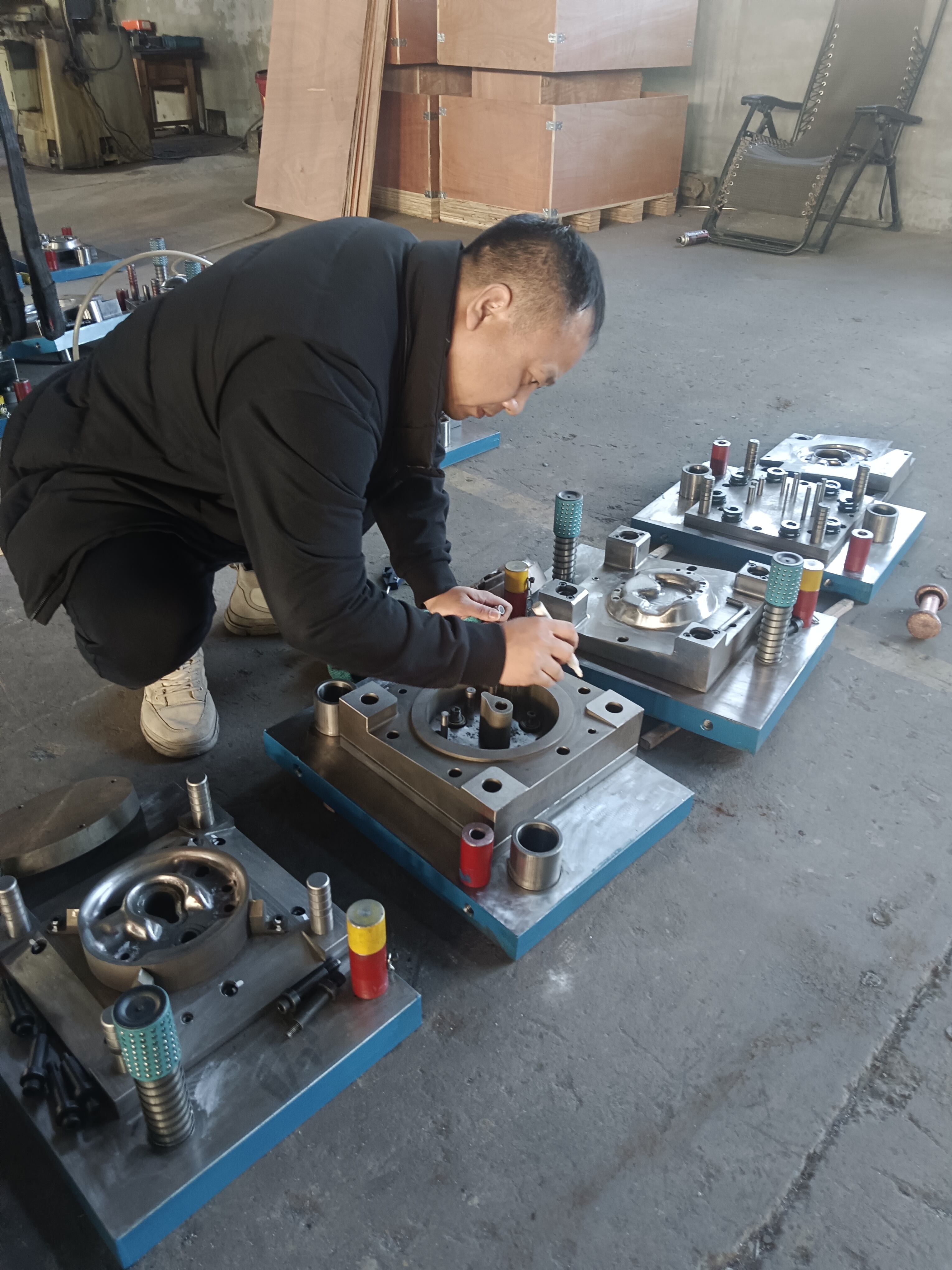
- Günlük Görsel Denetimler: Her üretim çalıştırmasından önce, açıkça görülen hasarlar, gevşek bileşenler ve biriken artıkları kontrol edin. Çalışma yüzeyleri ve kenarlarında çatlaklar, kırıklar veya deformasyonlar olup olmadığını gözlemleyin.
- Düzenli temizlik: Aşınmayı hızlandıran metal talaşlarını, yağlama birikintilerini ve diğer kirleticileri kaldırın. Temiz kalıplar daha iyi çalışır ve daha uzun ömürlüdür.
- Yağlama Kontrolleri: Tüm hareketli parçalarda, yön verici pimlerde ve aşınma yüzeylerinde uygun yağlamanın sağlandığını doğrulayın. Yetersiz yağlama sürtünmeye bağlı arızalara neden olur; fazla yağlama ise kirleticilerin birikmesine yol açar.
- Bağlantı Elemanı Denetimi: Gevşek konumlandırma pimleri, vidalar ve cıvataları kontrol edin. Sorunların bileşen arızalarına dönüşmesine izin vermeden önce, bağlantı elemanlarını doğru tork değerlerine göre sıkın.
- Yay durumu değerlendirmesi: Yayları, beklenen ömürlerinin sona ermesinden önce—kırılmaların üretimi kesintiye uğratmasından sonra değil—değiştirin.
Yüksek hacimli üretim için kapsamlı denetimleri her 10.000 vuruşta veya haftalık olarak, hangisi önce gelirse ona göre gerçekleştirin. Kritik bileşenler, geçmiş aşınma verilerine dayalı olarak belirli bir çevrim sayısından sonra dikkat gerektirebilir.
Gerçekçi önleyici bakım, kalıbın ne kadar iyi tasarlandığına bakılmaksızın düzenli aralıklarla ele alınması gereken öğeleri içerir. Kesme bölümlerinin bilenmesi, kalıp istasyonlarının ayar plakalarıyla (shim) ayarlanması ve aşınma desenlerinin denetlenmesi planlı faaliyetler olmalı—acil müdahaleler değil.
Aşınma Desenlerini Tanımak ve Kalıp Bakım Zamanlamasını Belirlemek
Kalıp takımlarınız durumlarını görünür işaretler aracılığıyla size bildirir—neye bakmanız gerektiğini biliyorsanız. Aşınma desenlerinin erken tespiti, felaket niteliğinde arızaları önler ve parça kalitesini korur.
Bakımın gerekli olduğunu gösteren aşağıdaki uyarı işaretlerine dikkat edin:
- Kabarık oluşumu: Basılmış parçalardaki kenar kıvrımı (burr) yüksekliğinin artması, bilenmeye ihtiyaç duyan körelmiş kesme kenarlarını gösterir.
- Boyutsal Sürüklenme: Parçaların tolerans sınırlarının dışına yavaşça çıkması, kritik kalıp yüzeylerinde aşınmayı gösterir.
- Yüzey Tutunması: Kalıp yüzeyleri ile iş parçası malzemesi arasında metal geçişi — pürüzlü lekeler veya malzeme birikimi olarak görünür.
- Çatlama veya Kırmalanma: Punch uçlarında veya kalıp kenarlarında görülen çatlaklar, acil müdahale gerektirir.
- Besleme Sorunları: Malzemenin ilerleyen kalıp preslerinden doğru şekilde ilerlememesi, genellikle aşınmış pilotlar veya yön verici bileşenleri işaret eder.
- Artan kesme kuvveti: Tonaj gereksinimlerindeki artış, kenar bozulmasını ve artan sürtünmeyi gösterir.
Kesme bölümlerini bilenirken aşağıdaki kurallara uyun: The Fabricator'ın bakım önerileri aşırı ısınmayı önlemek için her geçişte yalnızca 0,001 ila 0,002 inç (0,0254–0,0508 mm) kaldırın ve her keskinleştirme döngüsünde toplam malzeme kaldırma miktarını 0,005–0,010 inç (0,127–0,254 mm) ile sınırlayın. Taşlama işleminden sonra, doğru zamanlamayı korumak amacıyla uygun rondelalarla kalıp yüksekliğini ayarlayın.
Yenileme Kararı mı Yoksa Değişim Kararı mı?
Ne zaman yenileme işlemi mantıklıdır ve ne zaman aşınmış bileşenlerin değiştirilmesi gerekir? Bu karar birkaç faktöre bağlıdır:
- Hasarın Seviyesi: Hafif kenar aşınması, keskinleştirme işlemine iyi yanıt verir. Önemli çatlaklar veya yapısal hasar genellikle değişime ihtiyaç duyar.
- Kalan Malzeme: Kalıp bölümleri, minimum yükseklik sınırlarına ulaşılana kadar yalnızca belirli sayıda kez keskinleştirilebilir. Toplam malzeme kaldırma miktarını takip edin.
- Üretim Gereksinimleri: Kritik bir teslim tarihine yaklaşmak, uzun süren yenileme işlemine göre hızlı bileşen değişimini tercih etmenize neden olabilir.
- Maliyet Karşılaştırması: Yenileme maliyeti, yeni bileşenlerin satın alma maliyetinin %50–60’ına yaklaşırken, yeni bileşenler genellikle daha iyi uzun vadeli değer sağlar.
Depolama ve İşleme En İyi Uygulamalar
Kalıp damgalarını üretim aralarında nasıl sakladığınız ve nasıl işlediğiniz, ömürleri üzerinde doğrudan etki yaratır. Uygun uygulamalar, korozyonu, mekanik hasarı ve hizalama sorunlarını önler.
- İklimlendirme: Kalıpları kuru, sıcaklık kontrolü sağlanan ortamlarda saklayın. Paslanmayı önlemek için açığa çıkan çelik yüzeylere ince bir koruyucu yağ tabakası uygulayın.
- Uygun Destek: Ağır kalıplar için her zaman uygun kaldırma ekipmanları kullanın. Kalıpları yüzeyler boyunca sürüklemeyin veya taşıma sırasında sert nesnelerle temas etmelerine izin vermeyin.
- Koruyucu Kapaklar: Saklama sırasında kesici kenarları ve hassas yüzeyleri kazara temaslardan koruyun.
- Belgelendirme: Bütün bakım faaliyetlerine ilişkin ayrıntılı kayıtları, bilhassa bileme tarihlerini, kaldırılan malzeme miktarını ve değiştirilen bileşenleri içerecek şekilde tutun. Bu kayıt geçmişi, gelecekteki bakım planlamalarını yönlendirir.
Uygun bakım uygulamalarına zaman yatırımı, takım ömrünün uzaması, parça kalitesinin tutarlılığı ve öngörülebilir üretim programları yoluyla getiri sağlar. Bu uygulamalar, kalıp yatırımınızı azalan bir giderden uzun vadeli bir üretim varlığına dönüştürür—doğru maliyet analizi ve ROI hesaplamaları için temel oluşturur.
Kalıp Yatırımı İçin Maliyet Analizi ve ROI Değerlendirmeleri
Kalıp türünüzü seçtiniz, yüksek kaliteli malzemeleri belirlediniz ve bakım protokollerini oluşturduğunuza göre işte geceyi alacak soru: bu yatırım gerçekten geri dönüş sağlayacak mı? Maliyetleri doğrudan belirlenebilen daha basit imalat kararlarının aksine, presleme imalatı ekonomisi, hacmi ödüllendiren ancak yanlış hesaplamaları cezalandıran bir asimptotik eğri izler.
Kalıp yatırımı ile parça başına maliyet arasındaki bu ilişkiyi anlayabilmek, karlı sac şekillendirme operasyonlarını zarar eden operasyonlardan ayırır. Sac şekillendirme süreci, büyük başlangıç yatırımlarının parça başına birkaç sentlik üretim maliyetlerine dönüştüğü benzersiz bir maliyet yapısı yaratır—ancak yalnızca hesaplamalar sizin lehinize çalıştığında.
Kalıp Yatırımı Karşılaştırması ve Birim Başına Maliyetler
Her kalıp sac şekillendirme kararını yönlendiren temel denklem şudur:
Toplam Maliyet = Sabit Maliyetler (Tasarım + Kalıp + Kurulum) + (Birim Başına Değişken Maliyet × Miktar)
Kağıt üzerinde oldukça basit görünüyor—ancak detaylar içinde gerçek zorluk gizlidir. Buna göre otomotiv presleme maliyet analizi , kalıp yatırımları büyük ölçüde değişkenlik gösterir: Basit kesme kalıpları için yaklaşık 5.000 ABD Doları’ndan, çoklu şekillendirme istasyonlarına sahip karmaşık ilerleyici kalıplar için 100.000 ABD Doları’nın üzerine kadar.
Bu maliyet farklarını ne belirler? Aşağıdaki faktörleri göz önünde bulundurun:
- Kalıp karmaşıklığı: Parçanızdaki her özellik, kalıpta buna karşılık gelen bir istasyon gerektirir. Basit bir bağlantı parçası üç istasyon gerektirebilir; karmaşık bir otomotiv muhafazası ise yirmi istasyon gerektirebilir.
- Malzeme Sınıfı: 1 milyon darbe garantili yüksek kaliteli sertleştirilmiş takım çeliği, başlangıçta daha fazla maliyet gerektirir ancak bu yatırım, çok daha fazla parça üzerinden dağıtılmış olur.
- Hassasiyet gereksinimleri: Dar toleranslar, hassas taşlama, gelişmiş kaplamalar ve premium bileşenler gerektirir; bu da kalıp maliyetini artırır.
- Yüzey İşleme Gereksinimleri: Görünüş açısından önemli parçalar için cilalı şekillendirme yüzeyleri, ek makineleme ve bitirme işlemlerini gerektirir.
Ancak işte burada üretimde çekme (stamping) sürecinin ekonomik yapısı ilginç hale gelir. Beş yıl içinde 500.000 parça üreten 80.000 USD’lik ilerlemeli kalıp, parça başına yalnızca 0,16 USD’lik bir kalıp maliyeti ekler. Aynı kalıp yalnızca 5.000 parça üretiyorsa bu maliyet parça başına 16,00 USD’ye çıkar—bu durumda proje muhtemelen ekonomik olarak uygulanamaz hâle gelir.
Kalıp Türüne Göre Başa Baş Analizi
Farklı kalıp yapılandırmaları, farklı üretim hacmi eşiklerinde ekonomik olarak uygun hâle gelir. Bu başa baş noktalarını anlamak, hem aşırı yatırım hem de yetersiz yatırım hatalarını önler.
| Die türü | Tipik Yatırım Aralığı | Kar-Zarar Noktası Hacmi | Optimal Yıllık Üretim Hacmi | Maliyet Avantajı Gerçekleşir |
|---|---|---|---|---|
| Basit Aşamalı Kalıplar | $5,000–$15,000 | 1.000–3.000 parça | 10.000’in altında | Belirsiz talep için en düşük kalıp riski |
| Bileşik kalıplar | $15,000–$50,000 | 5.000–15.000 parça | 10,000–50,000 | Birleştirilmiş işlemler sayesinde azaltılmış işçilik |
| Kombinasyon Kalıpları | $20,000–$75,000 | 10.000–25.000 parça | 25,000–100,000 | Tek işlemde şekillendirme ve kesim |
| Ilerici kalıplar | $50,000–$500,000+ | 50.000–150.000 parça | 100,000+ | Yüksek üretim hacimlerinde parça başına en düşük maliyet |
| Taşıma matları | $75,000–$750,000+ | 25.000–75.000 parça | 50,000+ | Aksi takdirde imal edilemeyecek büyük/karmaşık parçaların üretimini mümkün kılar |
Deseni fark ettiniz mi? Kalıp yatırımları arttıkça, ekonomik olarak uygulanabilirlik için gerekli üretim hacmi eşiği de yükselir; ancak optimal üretim hacimlerinde parça başına maliyet avantajı daha belirgin hale gelir. Yıllık üretim hacmi 100.000 birimi aşan otomotiv projeleri için karmaşık ilerlemeli kalıplara yatırım yapmak, çevrim sürelerini ve işçilik miktarını büyük ölçüde azaltarak genellikle en düşük toplam sahiplik maliyetini sağlar.
Üretimde Değişken Maliyet Unsurları
Kalıbınız yapıldıktan sonra "parça fiyatı" devreye girer. Ham madde genellikle değişken parça fiyatının %60–%70’ini oluşturur. Bu sürekli maliyetleri anlayarak gerçek ROI’yi (Yatırım Getirisi) hesaplayabilirsiniz:
- Malzeme Maliyeti: Brüt Ağırlık × Malzeme Fiyatı/kg değerinden hurda ağırlık × hurda değeri/kg çıkarılarak hesaplanır. Verimli döşeme (nesting) atığı azaltır; ancak bazı hurda oluşumu kaçınılmazdır.
- Makine Saatlik Ücreti: Presler tonajlarına göre sınıflandırılır. Bir 600 tonluk pres, enerji tüketimi ve ekipman amortismanı nedeniyle bir 100 tonluk prese kıyasla daha yüksek saatlik ücretler talep eder.
- İşçilik Dağıtımı: Dakikada 60+ vuruş hızında çalışan yüksek hızlı ilerlemeli kalıplar için parça başına işçilik maliyeti, malzeme maliyetine kıyasla ihmal edilebilir düzeydedir.
- Genel Giderler ve Bakım: Kalıp bakımı—delici uçların bilenmesi ve aşınmış bölümlerin değiştirilmesi—için kalıp maliyetinin %2–5’lik yıllık bir tampon payı ayırın.
En düşük parça fiyatı genellikle yanıltıcıdır; gerçek hedef, en düşük Toplam Sahiplik Maliyetidir.
Kalıp Tedarikinde Teslim Süresi Etkenleri
Üretim Başlangıcına Geçiş Süresi, yatırım getirisinin (ROI) hesaplanmasını doğrudan etkiler. Her haftalık gecikme, fırsat gelirini kaybetmenize neden olur ve pahalı geçici çözümlere başvurmanızı zorunlu kılabilir. Sac kesme kalıbı üretim süreçlerini anlama, etkili planlamanıza yardımcı olur.
Tipik teslim süreleri şu şekilde dağılır:
- Tasarım Mühendisliği: karmaşıklık derecesine ve benzetim gereksinimlerine bağlı olarak 2–6 hafta
- Kalıp imalatı: standart ilerlemeli kalıplar için 8–16 hafta; karmaşık transfer sistemleri için daha uzun süre
- Deneme ve Doğrulama: i̇lk örnek alınması ve ayarlamalar için 2–4 hafta
- PPAP dokümantasyonu: Tam üretim parçası onayı gerektiren otomotiv uygulamaları için ek olarak 2–4 hafta
Kavramdan üretimde kullanıma hazır kalıp imalatına kadar geçen toplam süre genellikle 14–30 hafta sürer; bu, ürün piyasaya sürüm takvimleri açısından önemli bir planlama unsuru oluşturur.
Geliştirme Riskini Azaltma ve Üretime Geçiş Süresini Hızlandırma
Burada ortak seçimi, yatırım getirisinizin (ROI) hesaplamasını büyük ölçüde etkiler. İleri düzey yeteneklere sahip sac levha kalıp üreticileri, süreyi kısaltır ve maliyetli yinelemeleri azaltır.
CAE Simülasyonunun Etkisi: Geleneksel kalıp geliştirme sürecinde fiziksel kalıplar üretilir, deneme parçaları üretilir, sorunlar tespit edilir, kalıp değiştirilir ve süreç tekrarlanırdı—bazen onlarca maliyetli yineleme ile. Gelişmiş simülasyon teknolojisi, malzemenin davranışını sanal ortamda öngörerek fiziksel deneme yinelemelerini %50–%80 oranında azaltır.
Sertifikasyon Değeri: IATF 16949 sertifikalı üreticilerle çalışmak, otomotiv uygulamaları için kalite sistemlerinin zaten yerinde olduğunu garanti eder. Bu durum, niteliklendirme gecikmelerini ortadan kaldırır ve ileri seviyede maliyetli kalite sorunlarının riskini azaltır.
Hızlı prototipleme imkanları: Tasarım doğrulaması hızlı bir şekilde gerektiğinde, hızlı prototipleme hizmeti sunan üreticiler—bazıları 5 gün gibi kısa sürede 50 adet parça teslim edebilir—tam üretim kalıplamasına bağlı kalmadan daha hızlı karar verilmesini sağlar.
İlk değerlendirme onay oranları: İlk geçiş onay oranları arasında %70 ile %93 arasındaki fark, doğrudan daha az yineleme, daha hızlı üretim başlangıçları ve daha düşük toplam geliştirme maliyetleri anlamına gelir.
Piyasaya sürülme süresi ve OEM uyumluluğu önemli olduğu otomotiv uygulamaları için, Shaoyi —IATF 16949 sertifikasyonu, gelişmiş CAE benzetimi ve hızlı prototipleme yeteneklerini bir araya getiren—gibi üreticilerle iş birliği yapmak, geliştirme zaman çizelgelerini önemli ölçüde kısaltırken kalite riskini de azaltabilir.
Gerçek ROI’nizi Hesaplayın
Kalıp yatırımını değerlendirirken, parça başına basit karşılaştırmaların ötesine geçin. Gerçek ROI analizi şunları içerir:
- Toplam Teslim Maliyeti: Yabancı bir kalıp başlangıçta %30 daha ucuz olsa da, nakliye, liman gecikmeleri ve mühendislik değişikliği karmaşıklıkları sonrasında daha yüksek maliyet oluşturabilir.
- Kalite Maliyeti Önlemesi: Kusurlu parçalar hurda üretimine, yeniden işlenmeye ve olası ürün geri çağrımı sorumluluğuna neden olur. Nitelikli sac kesme kalıbı üreticilerinden temin edilen üst düzey kalıplar bu riskleri azaltır.
- Yaşam Döngüsü Değeri: 1 milyon vuruş garantili bir kalıp ile 100.000 vuruş garantili bir kalıp, parça başına kalıp maliyeti tahsisinde büyük fark yaratır.
- Esneklik değeri: Hızlı değişim yeteneği ve modüler tasarımlar, ürün tasarımının gelişmesiyle birlikte gelecekteki değişim maliyetlerini azaltır.
Doğru sac kesme kalıbı üretim maliyeti tahmini, başlangıç teklifinin ötesine geçerek toplam yaşam döngüsü ekonomisini anlamayı gerektirir. En Düşük Toplam Sahiplik Maliyetini — yalnızca en düşük kalıp fiyatını değil — sağlayan üreticiler, operasyonunuz için en büyük değeri yaratır.
Maliyet temelleri anlaşıldıktan sonra, son değerlendirme aşaması bu ekonomik vaatleri yerine getirebilecek bir üretim ortağı seçmeye odaklanır. Doğru ortak, bu teorik tasarrufları üretim gerçekliğine dönüştürür.
Doğru Kalıp Üretim Ortağını Seçme
Teknik bilgileri edindiniz—kalıp türleri, malzeme sınıfları, pres uyumluluğu, tasarım ilkeleri ve ROI hesaplamaları. Şimdi tüm bu bilgilerin üretim başarısına dönüşüp dönüşmeyeceği kararını vermeniz gereken aşama geldi: kalıplarınızı üretecek üretici ortağı seçme aşaması.
Kalıp ile presleme projeleriyle ilgili rahatsız edici gerçek şudur: Hatta kusursuz spesifikasyonlar bile yanlış ortak tarafından uygulandığında başarısız olur. Tasarım mühendisliği derinliğine sahip olmayan bir üretici, kritik tolerans gereksinimlerini kaçırabilir. Uygun kalite sistemlerine sahip olmayan bir üretici tutarsız sonuçlar sunar. Ayrıca ileri düzey simülasyon yeteneğine sahip olmayan bir ortak, ROI tahminlerinizi zayıflatmakta olan pahalı deneme-yanılma yinelemelerine maruz bırakır.
Peki, kalıp imalatında mükemmellik gerçekten nedir? Bu, spesifikasyonlarınızı güvenilir üretim kalıplarına dönüştüren mühendislik yeteneği, kalite sistemleri, üretim kapasitesi ve iletişim uygulamalarının bir araya gelmesidir. Şimdi bu makalede ele alınan tüm konuları, potansiyel ortakları değerlendirmek için uygulanabilir bir çerçeve haline getirelim.
Kalıp Seçim Kontrol Listesi
Herhangi bir potansiyel üretim ortağıyla görüşmeye başlamadan önce kendi projenizin gereksinimlerinin açıkça tanımlandığından emin olun. Bu kontrol listesi, hem kalıp tasarımı hem de ortak seçimi açısından kritik olan spesifikasyonları içerir:
- Hacim Gereksinimleri: Yıllık miktar tahminleri ve beklenen üretim ömrü (3 yıl mı? 10 yıl mı?)
- Parça Geometrisi Belgelendirmesi: Kritik boyutlar için GD&T belirtimleriyle tam CAD dosyaları
- Malzeme spesifikasyonu: Alaşım sınıfı, temper, kalınlık ve özel yüzey gereksinimleri
- Tolerans Hiyerarşisi: En sıkı kontrol gerektiren fonksiyon açısından kritik boyutların belirlenmesi
- Kalıp Türü Tercihi: Hacim analizinize göre ilerleyici, aktarım, bileşik veya kombinasyon temelli
- Pres Uyumluluğu: Tonaj, tabla boyutu ve strok karakteristikleri dahil olmak üzere mevcut pres spesifikasyonları
- Zamanlama gereksinimleri: Kalıp tamamlanması, ilk parça onayı ve üretim başlangıcı için hedef tarihler
- Bütçe parametreleri: Kâr-zarar eşik hesaplamalarınıza dayalı kabul edilebilir yatırım aralığı
- İkincil İşlemler: Herhangi bir sac kesme ve kalıp kesme, kenar düzeltme, kaplama veya montaj gereksinimleri
- Kalite belgeleri: PPAP seviyesi, muayene gereksinimleri ve sürekli SPC beklentileri
Bu spesifikasyonları açıkça belgelenmiş şekilde ortaklık görüşmelerine gelmek, fiyat teklifi sürecini hızlandırır ve gereksinimlerinizi gerçekten karşılayabilen üreticileri, sadece işi kazanmayı umanlarla ayırt eder.
Kalıp Üretim Ortaklarının Değerlendirilmesi
Gereksinimleriniz tanımlandıktan sonra bir potansiyel ortağın teslimat yapabilip yapamayacağını nasıl değerlendirirsiniz? Buna göre penn United Technologies’tan sektör kılavuzuna göre on temel faktör, nitelikli hassas kalıp ve presleme tedarikçilerini muhtemelen hayal kırıklığına uğratacak tedarikçilerden ayırır.
Deneyim ve Uzmanlık: Üretici firma ne zamandan beri faaliyet gösteriyor? Daha önce hangi tür bileşenleri preslemişler? Uzmanlıklarının düz parçalar, şekillendirilmiş parçalar ya da her ikisini de kapsayıp kapsamadığını ve dar toleranslar ile karmaşık geometrilerle ilgili geçmiş başarı kayıtlarını anlamak, projenizin yetkinliklerine uyup uymadığını ortaya koyar.
Tasarım ve Üretim Yetenekleri: Kalıpları kendi içinde tasarlayıp üretebiliyorlar mı? Hem tasarım hem üretim işlevlerini yürüten kalıp imalatçıları, tasarım kararlarının üretim sonuçlarını nasıl etkilediğini daha iyi bilirler. Kalıpları kendileri ürettiği için sorunları daha hızlı teşhis edebilir ve çözebilirler.
Proses Kontrol Sistemleri: ISO sertifikası, kalite sistemlerinin mevcut olduğuna dair temel bir güvence sağlar. Ancak daha derinlere inin: kontrol planlarını nasıl oluşturup yönetiyorlar? Hangi ölçüm ve muayene ekipmanlarına yatırım yapıyorlar? Bir tesisi ziyaret etmek, yalnızca bir sertifikadan çok daha fazla şeyi —kaliteye bağlılıklarını— ortaya koyar.
Kalıp bakım programları: Daha önce bahsedildiği gibi, doğru bakım kalıp ömrünü maksimize eder. Üretici, muayene programları, bileme aralıkları ve bileşen değiştirme gibi konuları kapsayan yapılandırılmış bakım programları sunuyor mu? Bu yetenek, toplam sahiplik maliyetinizi doğrudan etkiler.
Teslimat geçmiş kaydı: Zamanında teslimat metriklerini sorun. Bu performansı resmi olarak takip etmeyen üreticilerin üretim planlaması açısından zaman çizelgesine uyum sağlamada zorlandığı bilinir—bu, üretim planlaması için bir uyarı işareti olur.
Talep Yüklü Uygulamalar İçin Sertifikasyon Gereksinimleri
Otomotiv sac şekillendirme kalıpları projeleri için kalite sertifikaları, "olursa iyi olur" durumundan zorunlu hâle gelir. VPIC Group’un analizine göre dört sertifika, üreticinin uluslararası kabul görmüş standartlara bağlılığını gösterir:
- IATF 16949: Otomotiv endüstrisinin kalite yönetim standardı, ISO ile birlikte geliştirilmiştir ve güvenli ve güvenilir otomotiv ürünlerine ilişkin gereksinimleri belirler. Bu sertifika, bir kalıp üretimi ortağının ürün ve süreç geliştirme açısından otomotiv OEM'lerinin talep ettiği teknikleri ve yöntemleri uyguladığını gösterir.
- ISO 9001: Kalite yönetim sistemleri için kriterler belirler ve müşteri hizmetlerinde, işletme maliyetlerinde, yasal uyumda ve risk yönetimi alanında iyileşmeyi gösterir.
- ISO 14001: Kuruluşun çevresel sürdürülebilirliğe yönelik taahhüdünü, kurulmuş çevresel yönetim sistemleri aracılığıyla gösterir.
- ISO 45001: Çalışan güvenliğini ve işyeri risklerini azaltmayı ele alır—özellikle teknisyenlerin ağır makinalarla çalıştığı presleme operasyonlarında büyük önem taşır.
Bu sertifikalar yasal olarak zorunlu değildir; bu nedenle sahip olan üreticiler, katı standartlara uyum sağlamak amacıyla gönüllü olarak yatırım yapmışlardır. Bu ek çaba, genel operasyonel mükemmelliğe paralel olarak gerçekleşir.
Riski Azaltan Mühendislik Yetkinlikleri
Sertifikaların ötesinde, zaman çizelgelerini kısaltan ve maliyetli yinelemeleri önleyen teknik yetenekleri değerlendirin:
- CAE Benzetimi: Gelişmiş şekillendirme simülasyonu, fiziksel kalıpların henüz mevcut olmadığı aşamada malzeme davranışını öngörür ve deneme yinelemelerini %50–%80 oranında azaltır.
- Hızlı prototip oluşturma: Prototip parçaları hızlıca üretme yeteneği—bazı üreticiler bu süreyi yalnızca 5 güne indirgemektedir—üretim kalıplarına bağlı kalmadan tasarım doğrulamasının yapılmasını sağlar.
- İlk değerlendirme onay oranları: Geçmiş PPAP ilk geçiş onay oranları hakkında sorun. %93 ve üzeri oranlara ulaşan üreticiler, daha az yineleme ve daha hızlı üretim başlangıcı ile sonuçlanan mühendislik disiplinini gösterir.
- Malzeme Uzmanlığı: Standart çelik, paslanmaz çelik, alüminyum ya da egzotik alaşımlar gibi belirli malzemenizle ilgili deneyim, projeniz sırasında öğrenme eğrisi kaynaklı sorunları önler.
Son Seçimi Yapmak
Gereksinimler kontrol listesi ve değerlendirme kriterlerinizle donanarak adayları aşağıdaki sırayla daraltın:
- İlk Değerlendirme: Sertifikaları doğrulayın, benzer projelerden oluşan portföyü inceleyin ve kapasite mevcudiyetini teyit edin.
- Teknik Tartışma: Belirtimlerinizi sunun ve sorularının derinliğini değerlendirin. Ana özellikler, toleranslar ve kalite gereksinimleri hakkında ayrıntılı bilgi isteyen üreticiler, başarıyı öngören dikkat düzeyini gösterir.
- Tesis Değerlendirmesi: Mümkünse üretim tesisini ziyaret edin. Ekipman durumunu, düzeni ve personelin kalite sistemleriyle etkileşim biçimini gözlemleyin.
- Referans Doğrulaması: Benzer projelerden referanslar isteyin ve teslimat performansı, kalite tutarlılığı ile sorunlara verilen yanıt hızı konularında takip yapın.
- Toplam Değer Karşılaştırması: Teklifleri yalnızca başlangıç kalıp maliyetine göre değil, toplam sahip olma maliyetine göre değerlendirin. Teslim süresi, kalite riski, bakım desteği ve iletişimde yanıt verme hızını da dikkate alın.
Yüksek hassasiyetli kalıp ve presleme uygulamaları için—özellikle IATF 16949 uyumluluğu gerektiren otomotiv projeleri kapsamında—sertifikalı kalite sistemlerini, gelişmiş simülasyon yeteneklerini ve kanıtlanmış ilk geçiş onay oranlarını bir araya getiren üreticilerle iş birliği yapmak, toplam riski en aza indirir. Shaoyi'nin otomotiv pres kalıp çözümleri bu kombinasyonu örnekleyen üreticiler, hızlı prototipleme, CAE destekli ürün geliştirme ve OEM standartlarına özel olarak uyarlanmış yüksek hacimli üretim kapasiteleri sunar.
Bugün seçtiğiniz presleme kalıbı, yıllarca—hatta on yıllarca—parça üretmeye devam edecektir. Seçtiğiniz üretici, bu kalıbın güvenilir bir üretim varlığı haline gelip gelmeyeceğini ya da sürekli kalite sorunlarına ve bakım zorluklarına neden olan bir kaynak olup olmayacağını belirler. Ortaklarınızı kapsamlı şekilde değerlendirmek için gereken zamanı ayırın; böylece kalıp yatırımınız, hesaplamalarınızla öngörülen ROI’yi sağlayacaktır.
Şekillendirme Presi Kalıpları Hakkında Sıkça Sorulan Sorular
1. Birinci sınıf. Bir metal damgalama matrosu ne kadar eder?
Metal kalıp presleme maliyetleri, karmaşıklık derecesine göre büyük ölçüde değişir; basit kesme kalıpları için 5.000 ABD Doları’ndan, çoklu şekillendirme istasyonlarına sahip karmaşık ilerlemeli kalıplar için 500.000 ABD Doları’nın üzerine kadar çıkabilir. Basit bileşik kalıplar genellikle 15.000–50.000 ABD Doları, birleşik kalıplar ise 20.000–75.000 ABD Doları arasındadır. Büyük otomotiv bileşenleri için kullanılan taşıma kalıpları 750.000 ABD Doları’nı aşabilir. Anahtar nokta, yatırımınızı üretim hacmiyle uyumlandırmaktır: 50.000 ABD Doları değerindeki bir ilerlemeli kalıpla 500.000 adet parça üretilmesi durumunda kalıp maliyeti parça başına yalnızca 0,10 ABD Doları ekler; bu da yüksek hacimli uygulamaları son derece maliyet etkin kılar.
2. Pres kalıbı işlemi nedir?
Pres kalıp işlemi, hassas olarak tasarlanmış üst ve alt kalıp yarısının bir pres makinesine monte edilmesini içerir. Aktive edildiğinde pres, üst kalıbı kontrollü bir kuvvetle aşağı doğru hareket ettirir—bu kuvvet bazen yüzlerce tondan fazla olabilir. Çekici (punch), kalıp yarısı arasına yerleştirilen sac levha ile buluştuğunda, malzemeyi keser (boşaltma veya delme), belirli açılarla bükülmesini sağlar ya da üç boyutlu şekillere çekerek biçimlendirir. Çekici ile kalıp arasındaki açıklık, genellikle her bir tarafta malzeme kalınlığının %8–10’u kadardır ve bu açıklık, kenar kalitesini ve takım ömrünü doğrudan etkiler.
3. Kesim kalıbı ile sac işleme arasındaki fark nedir?
Kalıp kesimi ve metal presleme temelde farklı süreçlerdir. Kalıp kesimi genellikle kağıt, plastik veya ince levhalar gibi düz malzemelerin, keskin kenarlı kalıplar kullanılarak kesilmesini ifade eder; bu işlem, kurabiye kesmeye benzer. Metal presleme ise sertleştirilmiş takım çeliğinden yapılmış kalıplarla, büyük basınç altında sac metaller üzerinde kesme, şekillendirme, bükme ve çekme işlemlerini kapsar. Presleme, tek bir operasyonda çoklu özelliklere sahip karmaşık üç boyutlu parçalar üretebilirken, kalıp kesimi genellikle iki boyutlu profillere sınırlıdır.
4. Presleme kalıplarının dört ana türü nelerdir?
Dört ana kalıp tipi ilerleyici, taşıyıcı, bileşik ve birleşik kalıplardır. İlerleyici kalıplar, malzemenin pres boyunca ilerlemesiyle sıralı olarak farklı işlemler gerçekleştiren çoklu istasyonlara sahiptir; bu nedenle küçük ve orta boyutlu parçaların yüksek hacimli üretiminde idealdir. Taşıyıcı kalıplar, parçaları istasyonlar arasında mekanik tutucularla hareket ettirerek daha büyük ve karmaşık bileşenleri işleyebilir. Bileşik kalıplar, hassas özellik hizalaması için tek bir vuruşta birden fazla kesme işlemini aynı anda gerçekleştirir. Birleşik kalıplar ise orta hacimli üretim için kesme ve şekillendirme işlemlerini tek bir istasyonda birleştirir.
5. İlerleyici ve taşıyıcı kalıplar arasında nasıl seçim yaparım?
Yüksek hacimli üretim (yılda 100.000+ adet) gerektiren, küçük ve orta boyutlu parçalar için ilerleyici kalıpları seçin; bu parçalar, tüm şekillendirme istasyonları boyunca taşıyıcı şeride bağlı kalabilmelidir. Parçalar, şerit tabanlı ilerleme için çok büyükse, işlemler arasında yeniden konumlandırılmaları gerekiyorsa veya şekillendirme sırasında çevrilmesi ya da döndürülmesi gereken karmaşık geometrilere sahipse, transfer kalıpları tercih edilmelidir. Transfer kalıpları, otomotiv gövde panelleri ve yapısal bileşenler için üstün performans gösterirken, ilerleyici kalıplar elektronik ürünleri, bağlantı elemanlarını ve küçük otomotiv donanımlarının üretiminde önceliklidir.