 Small batches, high standards. Our rapid prototyping service makes validation faster and easier —

Steel Plate Fabrication Decoded: From Raw Slab To Finished Product
What Steel Plate Fabrication Actually Means
Ever wondered what separates a massive bridge support beam from a car door panel? The answer lies in thickness—and that distinction fundamentally changes how manufacturers work with the material. Steel plate fabrication refers to the specialized processes used to cut, form, weld, and assemble steel plates—materials typically 3/16 inch (0.187") or thicker—into finished structural components. Unlike steel sheet metal work, which handles thinner, more flexible materials, plate fabrication demands heavier equipment, different techniques, and a deeper understanding of how thick steel behaves under stress.
So what is steel sheet, and how does it differ from plate steel? According to industry standards from Econ Steel, steel sheet is categorized as any material under 0.187" thick, while the steel plate exceeds this threshold. This seemingly simple measurement creates a fundamental divide in fabrication methods, equipment requirements, and end-use applications.
Plate vs Sheet Metal Thickness Standards
Understanding thickness classifications helps you navigate material specifications with confidence. The gauge system—inherited from 19th century British wire manufacturing—can be confusing because higher gauge numbers actually indicate thinner materials. For steel plates, manufacturers typically specify thickness in decimal inches or millimeters rather than gauge numbers.
| Classification | Thickness Range | Gauge Reference | Typical Applications |
|---|---|---|---|
| Steel Sheet (Light) | 0.015" - 0.059" | 28 - 16 gauge | Appliance housings, HVAC ductwork, automotive panels |
| Steel Sheet (Heavy) | 0.060" - 0.186" | 15 - 7 gauge | Roofing, structural decking, equipment enclosures |
| Steel Plate (Standard) | 0.187" - 3.0" | N/A (decimal inches) | Pressure vessels, storage tanks, structural beams |
| Steel Plate (Heavy) | 3.0" and above (up to 6" standard) | N/A (decimal inches) | Ship hulls, bridge components, heavy machinery bases |
Steel plates come in two primary manufacturing categories. Plate Mill Plates (PMP) are rolled individually from ingots with widths of 84", 96", or 120" and thicknesses from 0.1875" to 6". Continuous Mill Plates (CMP) originate from cast slabs and come in narrower widths of 48", 60", or 72" with thicknesses between 0.1875" and 0.500".
Why Thickness Determines Fabrication Method
Imagine trying to fold a piece of paper versus bending a wooden board—the techniques required are completely different. The same principle applies when comparing plate steel plate fabrication to sheet metal work. Steel plates demand:
- Heavier cutting equipment: Plasma, laser, or waterjet systems capable of penetrating thick material
- Larger press brakes: Machines generating hundreds or thousands of tons of force for bending
- Multi-pass welding: Joint preparations requiring beveled edges and multiple weld passes
- Thermal management: Preheat and interpass temperature controls to prevent cracking
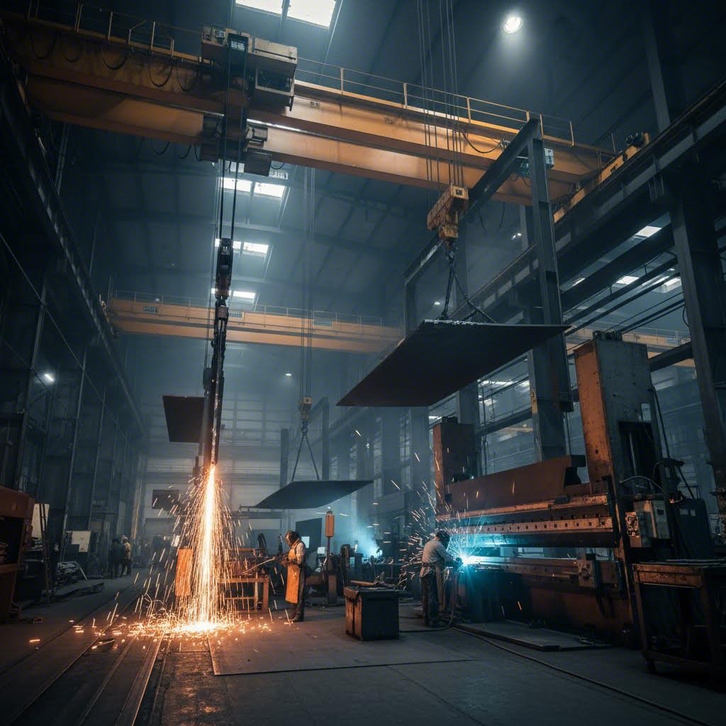
- Specialized handling: Overhead cranes and rigging for moving heavy components
For structural applications—think pressure vessels, storage tanks, bridge girders, and ship hulls—thickness provides the load-bearing capacity and durability these components require. Steel plates withstand heavy stress, resist deformation under extreme loads, and deliver the structural integrity that thinner materials simply cannot match. The core fabrication processes for steel plates include precision cutting, forming and bending, welding, and rigorous quality inspection—each adapted specifically for the challenges that thick material presents.
Steel Plate Cutting Methods Explained
Once you have the right steel plate material, the next critical question becomes: how do you cut it? Choosing the wrong metal cutting technology can waste thousands in material, add unnecessary processing time, and compromise edge quality. Each cutting method brings distinct advantages depending on your steel plate thickness, precision requirements, and production volume.
Four primary technologies dominate modern steel plate fabrication: laser cutting for precision work, plasma cutting for thick steel plate and speed, waterjet cutting for heat-sensitive applications, and mechanical shearing for straight-line production. Understanding when to deploy each method separates efficient fabrication shops from those burning money on the wrong approach.
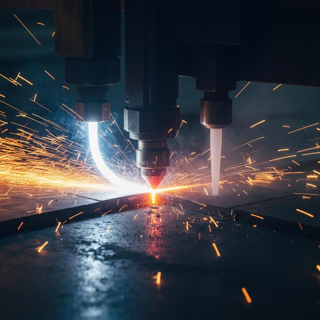
Laser Cutting Precision and Limitations
Laser cutting uses a focused high-power density beam to rapidly melt, vaporize, or ablate material while a coaxial gas stream blows away molten metal. The result? Exceptionally clean edges with minimal post-processing requirements. For thin to medium-thickness plates, nothing matches laser's combination of speed and accuracy.
When does laser cutting make sense? Consider these scenarios:
- Intricate patterns and small holes: The focused beam creates sharp corners and precise geometries impossible with other methods
- Tight tolerances: Dimensional accuracy reaches ±0.2mm, with slit widths around 0.5mm
- High-volume thin material: Cutting 2mm mild steel at 600cm/min makes mass production viable
- Minimal secondary processing: Both sides of the slit remain parallel and perpendicular to the surface
However, laser cutting hits practical limits as thickness increases. Industrial applications for carbon steel generally stay below 20mm, with stainless steel typically under 16mm. Beyond these thresholds, cutting speed drops dramatically, and other technologies become more cost-effective. For context, understanding how thick 16 gauge steel is (approximately 0.0598" or 1.5mm) helps illustrate that laser excels in this thinner range while plasma takes over for heavier plates.
Plasma vs Waterjet Selection Criteria
When material thickness exceeds laser's sweet spot, plasma and waterjet cutting compete for dominance—but they serve fundamentally different purposes.
Plasma cutting uses an electrical arc and compressed gas to melt and blast through conductive metals. According to testing by Wurth Machinery, plasma cutting 1-inch steel runs 3-4 times faster than waterjet, with operating costs roughly half as much per foot. The technology shines when working with thick conductive metals while keeping budgets manageable.
Key plasma advantages include:
- Optimal cutting range from 0-120mm, with best quality around 20mm thickness
- Equipment costs around $90,000 versus $195,000 for comparable waterjet systems
- Excellent performance on structural steel, heavy equipment, and shipbuilding applications
- Accuracy within 1mm—sufficient for many industrial applications
Waterjet cutting takes a completely different approach. High-pressure water mixed with abrasive particles cuts through virtually any material—steel, stone, glass, composites—without generating heat. This cold cutting process eliminates thermal deformation, heat-affected zones, and material property changes.
Choose waterjet when:
- Heat damage must be avoided (aerospace components, heat-treated materials)
- Material versatility matters (cutting metals and non-metals on the same machine)
- Precision requirements demand ±0.1mm accuracy, or ±0.02mm with dynamic waterjet
- Thickness ranges from 0.8mm to 100mm or beyond
The tradeoff? Waterjet runs significantly slower than plasma and carries higher equipment and operating costs. The technology projected to reach over $2.39 billion by 2034 according to market research, but it fills a specific niche rather than replacing thermal cutting methods.
Mechanical Shearing for High-Volume Production
Sometimes the simplest solution works best. Mechanical shearing—using opposing blades to slice straight lines through steel plates—remains relevant for high-volume production of straight cuts. While lacking the flexibility of CNC-controlled methods, shearing delivers unmatched speed for blanking operations and straight-edge trimming.
Shearing works best for:
- Straight-line cuts only (no curves or complex geometries)
- High-volume blanking where speed outweighs precision
- Pre-cutting plates before secondary CNC operations
- Cost-sensitive applications where edge quality requirements are modest
| Cutting Method | Max Thickness Capacity | Edge Quality | Heat-Affected Zone | Relative Cost Per Cut | Best Applications |
|---|---|---|---|---|---|
| Laser Cutting | Carbon: 20-40mm; Stainless: 16-25mm | Excellent (±0.2mm) | Minimal | Medium-High | Precision parts, thin sheets, intricate patterns |
| Plasma Cutting | 0-120mm (optimal ~20mm) | Good (within 1mm) | Moderate | Low | Thick steel plate, structural steel, heavy equipment |
| Waterjet Cutting | 0.8-100mm+ | Excellent (±0.1mm) | None (cold cut) | High | Heat-sensitive materials, aerospace, mixed materials |
| Mechanical Shearing | Varies by machine | Moderate | None | Very Low | Straight cuts, high-volume blanking |
Many fabrication shops eventually incorporate multiple cutting technologies. Plasma and laser pair well—plasma handles thick plates while laser tackles precision thin-gauge work. Adding waterjet provides unmatched versatility for specialty applications. The key lies in matching technology to your most common jobs, then expanding capabilities as business demands grow.
With cutting methods selected, the next challenge emerges: transforming flat steel plates into three-dimensional components through forming and bending operations.
Forming and Bending Heavy Steel Plates
A flat steel plate sitting in your shop holds tremendous potential—but it takes precise forming operations to unlock that potential and create functional three-dimensional components. Whether you need angular brackets, cylindrical tanks, or complex curved surfaces for shipbuilding, the transformation from flat stock to formed plate requires understanding how thick steel behaves under stress and which techniques deliver the results you need.
Unlike thin sheet metal that bends easily with modest force, structural steel plate demands serious tonnage and careful planning. The same properties that make plate ideal for load-bearing applications—thickness, strength, rigidity—create challenges during forming. Get it right, and you produce precise components ready for welding and assembly. Get it wrong, and you waste expensive material while potentially damaging equipment.
Press Brake Operations for Angular Components
Press brake bending remains the workhorse operation for creating angular forms in steel fabrication. The process sounds simple: a punch forces the plate into a die, creating a bend at a specific angle. In practice, heavy plate fabrication involves significant complexity.
Imagine bending a 1-inch thick steel plate to a 90-degree angle. You need equipment generating hundreds—sometimes thousands—of tons of force. The relationship between plate thickness and required tonnage isn't linear; doubling thickness can quadruple the force needed. Beyond raw power, operators must account for:
- Minimum bend radius: Thicker plates require larger inside radii to prevent cracking. As a general rule, minimum bend radius equals 1-2 times the material thickness for carbon steel, though this varies by grade
- Die opening selection: The V-die opening typically ranges from 6-12 times material thickness. Wider openings reduce required tonnage but produce larger radii
- Bend orientation: Bending perpendicular to the rolling direction (grain) allows tighter radii than bending parallel to it
- Material condition: Normalized or annealed plates form more readily than as-rolled material
Modern CNC press brakes calculate bend allowances, tonnage requirements, and springback compensation automatically. However, experienced operators understand that theoretical calculations only get you close—actual results depend on material batch variations, tooling condition, and environmental factors.
Roll Forming Cylindrical Structures
When your application calls for curved surfaces rather than angular bends—think pressure vessels, storage tanks, or pipe sections—roll forming takes center stage. Three-roll or four-roll plate bending machines progressively curve flat plates into cylindrical or conical shapes.
The process works by passing the plate between rolls multiple times, gradually increasing curvature with each pass. For a structural steel plate destined for tank construction, this might mean dozens of passes to achieve the target diameter without overstressing the material. Four-roll machines offer an advantage here: the top roll clamps the plate while side rolls do the bending work, providing better control and reducing flat spots at the leading edge.
Forming cylindrical plate structures demands attention to:
- Pre-bending the edges: Without proper edge preparation, the first and last portions of the plate remain flat, requiring additional processing
- Consistent material thickness: Variations across the plate width create uneven curvature and misalignment during welding
- Out-of-roundness tolerances: Critical applications like pressure vessels may require post-forming stress relief and precision measurement
Managing Springback in Heavy Plate
Here's the challenge every plate fabrication professional faces: steel doesn't stay where you put it. After releasing the forming pressure, the material springs back partially toward its original flat state. This elastic recovery—called springback—can represent several degrees of angle in thick plate work.
Why does this happen? During bending, the outer surface stretches while the inner surface compresses. The neutral axis experiences no length change. When pressure releases, the elastically strained material wants to return to its unstressed state. Higher-strength steels exhibit greater springback because they resist permanent deformation more effectively.
Traditional compensation involves overbending—applying more bend angle than required, anticipating the springback. Experienced operators develop intuition for specific materials and thicknesses. However, complex curved surfaces—particularly in shipbuilding where hull plates require compound curvatures—demand more sophisticated approaches.
Research from shipyard applications demonstrates how multi-point press forming combined with finite element analysis enables automated springback compensation. By simulating the forming process computationally, engineers can calculate the exact piston strokes needed to achieve the desired final shape after springback. This iterative displacement adjustment method minimizes shape deviation between design intent and manufactured reality—critical when assembling hundreds of unique curved plates into a ship hull.
Factors affecting formability extend beyond basic material properties:
- Grain direction: Rolling processes create directional properties; forming perpendicular to the grain typically yields better results
- Material grade: Higher-strength grades offer greater structural capacity but require more force and exhibit more springback
- Temperature considerations: Some applications use hot forming to reduce required forces and enable tighter radii, though this adds process complexity
- Yield strength: Materials with higher yield strength resist initial deformation, requiring greater overbend compensation
- Ductility: More ductile materials tolerate tighter bend radii without cracking
- Surface condition: Scale, rust, or surface defects can initiate cracks during forming
The relationship between plate structure and forming behavior becomes particularly important for structural steel and plate applications where the finished component must meet precise dimensional requirements. Whether you're forming simple brackets or complex curved sections, success depends on matching forming methods to material properties while accounting for the inevitable springback.
Once forming operations transform flat plates into three-dimensional shapes, the next critical phase begins: joining those components through welding techniques specifically adapted for thick plate materials.
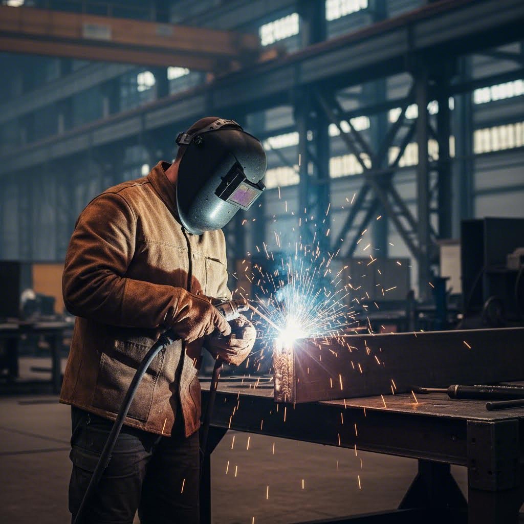
Welding Techniques for Plate Fabrication
You've cut the plates to size and formed them into shape—now comes the process that determines whether your fabricated assembly will perform for decades or fail prematurely. Welding thick steel plates isn't simply a scaled-up version of sheet metal joining. The physics change dramatically when you're depositing multiple weld passes into beveled joints on material measured in inches rather than gauge numbers. Every decision—from process selection to heat management—directly impacts the structural integrity of welded steel components.
Sound complex? It is. But understanding the fundamentals transforms this challenge into a predictable, controllable operation. Whether you're fabricating pressure vessels, welded steel pipe assemblies, or structural connections, the principles remain consistent: match the welding process to the application, prepare joints correctly, and manage heat throughout the operation.
Selecting the Right Welding Process for Plate Thickness
Four primary arc welding processes dominate heavy plate fabrication, each bringing distinct advantages depending on your specific requirements.
Shielded Metal Arc Welding (SMAW)—commonly called stick welding—uses flux-coated consumable electrodes that generate their own shielding gas. This portability makes SMAW ideal for field work, structural steel erection, and shipbuilding repair where external gas supplies aren't practical. According to industry safety resources, electrode types like E7018 (low-hydrogen) and E6010 allow operators to match parameters to material grade, thickness, and position. The tradeoff? Lower deposition rates mean longer welding times on thick sections.
Gas Metal Arc Welding (GMAW)—or MIG welding—feeds solid wire through a torch while external shielding gas protects the weld pool. Higher deposition rates and easier operation make GMAW popular for shop fabrication. Using ER70S-6 solid wire with a C25 blend (75% argon / 25% CO₂) delivers smooth wetting and moderate penetration ideal for carbon steel plates.
Flux-Cored Arc Welding (FCAW) bridges the gap between SMAW and GMAW. The tubular wire electrode contains flux that produces both shielding and slag, enabling high deposition rates with deep penetration. You'll find FCAW in heavy fabrication, shipbuilding, and structural applications. The dual-shield configuration (with external gas) maximizes deposition in shop conditions, while self-shielded variants handle windy field environments. Its robust arc welds through mill scale and rust more effectively than GMAW, reducing surface preparation time.
Submerged Arc Welding (SAW) delivers the highest deposition rates of all—making it the go-to choice for long, continuous welds on flat or horizontal joints. A granular flux blanket covers the arc, providing excellent protection while enabling deep penetration on thick plate. Automated track-mounted SAW systems excel at panel joining in shipyards and fabricating large-diameter welded steel pipes and rolled pipe assemblies. The process isn't suitable for all positions, but when applicable, nothing matches its productivity.
Joint Preparation Standards for Structural Integrity
Here's a principle every experienced fabricator knows: a weld is only as good as the joint preparation. On thick plate work, proper joint design and preparation separate reliable structural connections from potential failure points.
According to welding preparation guidelines from ESAB University, preparation begins with contaminant removal. Oil, grease, cutting fluids, and lubricants must go first—use non-chlorinated cleaners like acetone in well-ventilated areas. Next, wire brushing or grinding removes rust, scale, paint, and cutting dross. When welding stainless steel tube or aluminum components, dedicate separate stainless-steel brushes and grinding wheels to prevent cross-contamination.
For plates over 1/4 inch thick, beveling the joint edges becomes essential. Standard practice calls for:
- V-groove joints: Approximately 30-degree bevel on each side, creating a 60-degree included angle
- T-joints: Single 45-degree bevel on one member
- Land preparation: Don't bevel to a knife edge—leave 1/16" to 1/8" thickness at the root to support arc heat
- Root opening: A gap between members (typically 1/16" to 1/8") helps ensure full penetration, especially with limited-amperage equipment
Backing bars or strips provide support for root passes when welding from one side only. The backing material—steel, ceramic, or copper—prevents melt-through while maintaining proper root geometry. For critical applications like pressure vessels or welded pipes requiring full radiographic inspection, proper backing eliminates incomplete fusion defects.
Heat Management in Heavy Plate Welding
Thick steel acts like a massive heat sink, rapidly drawing thermal energy away from the weld zone. Without proper heat management, this cooling rate creates problems: hydrogen-induced cracking, excessive hardness in the heat-affected zone, and residual stress that can distort assemblies or initiate fatigue failures.
Preheat requirements address the cooling rate issue by raising the base metal temperature before welding begins. The thicker the plate and the higher the carbon equivalent of the steel, the more preheat you need. Common structural grades like A36 may require 150-300°F preheat on plates over 1 inch thick, while higher-strength grades demand even higher temperatures. Use temperature-indicating crayons ("temp sticks") that melt at specific temperatures to verify preheat—mark outside the weld zone to avoid contamination.
Interpass temperature control maintains proper conditions throughout multi-pass welding. Maximum interpass temperatures (typically 400-500°F depending on grade) prevent excessive heat buildup that can degrade mechanical properties. Minimum interpass temperatures ensure adequate ductility between passes. Monitoring both limits becomes critical on thick sections requiring dozens of weld passes.
Post-weld heat treatment (PWHT) relieves residual stresses in completed weldments. Critical applications—pressure vessels, thick structural connections, sour service pipelines—often require controlled heating to specific temperatures (typically 1100-1200°F for carbon steel), holding at temperature, then slow cooling. PWHT improves dimensional stability, reduces hardness in heat-affected zones, and mitigates hydrogen embrittlement risks.
The following sequence outlines the complete process for executing multi-pass welds on thick plate material:
- Clean the joint: Remove all oil, grease, rust, scale, paint, and cutting residue using appropriate solvents and mechanical methods
- Prepare the bevel: Machine or grind proper bevel angles, land dimensions, and root opening per welding procedure specification
- Verify fit-up: Confirm alignment, root gap consistency, and backing bar placement if used
- Apply preheat: Heat the joint area to the specified temperature and verify with temperature-indicating methods
- Weld the root pass: Establish the foundation weld using appropriate technique for full penetration
- Clean between passes: Remove slag and spatter before depositing subsequent layers
- Monitor interpass temperature: Verify temperature stays within specified minimum and maximum limits before each pass
- Complete fill and cap passes: Build up the joint with proper bead placement and overlap
- Perform visual inspection: Check for surface defects, proper profile, and dimensional conformance
- Apply PWHT if required: Follow specified heating rate, hold temperature, and cooling rate procedures
Following these steps consistently produces welded steel assemblies—whether structural beams, pressure vessels, or welded steel pipes—that meet design requirements and pass rigorous inspection. Speaking of inspection, the next critical phase ensures every weld meets quality standards before components enter service.
Quality Control and Industry Certifications
Every weld you've deposited, every plate you've formed—none of it matters if the finished product fails inspection. Quality control in steel plate fabrication isn't just a checkbox exercise; it's the systematic verification that transforms raw materials and skilled labor into components worthy of critical service. When a pressure vessel holds thousands of gallons under extreme conditions, or a structural beam supports a building for decades, the inspection and documentation behind that component provides the confidence that it will perform as designed.
How do fabricators prove their work meets specifications without destroying the very components they've built? The answer lies in non-destructive testing methods, industry certifications, and rigorous documentation systems that trace every material and process from incoming steel to final shipment.
Non-Destructive Testing Methods Compared
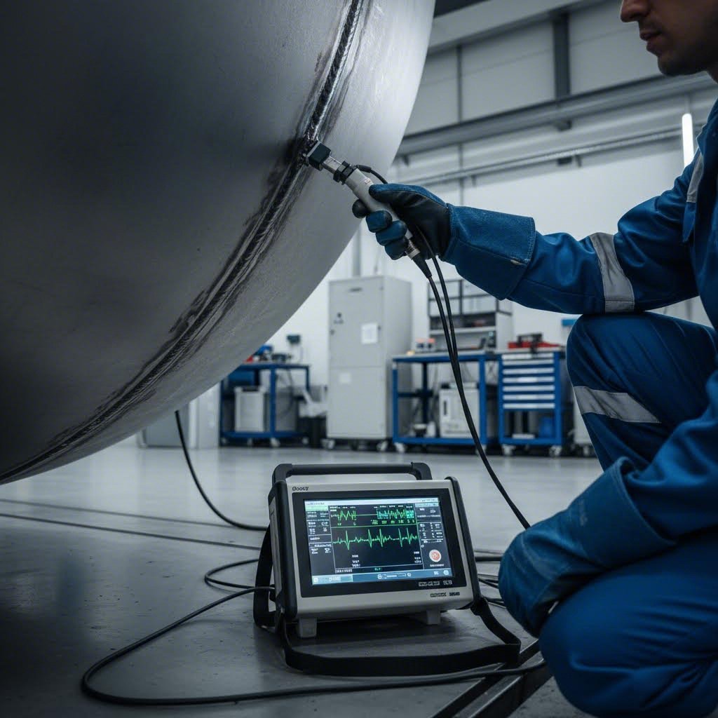
Non-destructive testing (NDT) examines materials and welds without damaging them—think of it as a medical diagnostic for steel. According to Voliro's comprehensive NDT guide, these techniques detect flaws, cracks, voids, and discontinuities invisible to the naked eye, ensuring structural integrity before components enter service.
Four primary NDT methods dominate steel plate fabrication:
Ultrasonic Testing (UT) uses high-frequency sound waves to detect internal defects. When sound waves encounter a crack, void, or inclusion, some energy reflects back to the transducer—similar to sonar detecting objects underwater. UT excels at finding subsurface flaws in thick plates and welds, measuring wall thickness, and identifying laminations. Modern phased-array UT provides detailed cross-sectional images of weld joints, making it invaluable for pressure vessel manufacturing and critical structural connections.
Radiographic Testing (RT) passes X-rays or gamma radiation through materials, exposing film or digital detectors on the opposite side. Darker areas indicate where more radiation passed through, revealing internal voids, porosity, or incomplete fusion. While radiography provides permanent documentation and detects volumetric defects effectively, it requires strict safety protocols and specialized equipment. For fabrication of pressure vessel components, radiographic examination of butt welds often represents a mandatory requirement.
Magnetic Particle Testing (MT) detects surface and near-surface discontinuities in ferromagnetic materials. Technicians apply a magnetic field to the test piece, then dust it with iron particles. Defects disrupt the magnetic field, causing particles to cluster visibly at crack locations. MT works quickly and inexpensively for weld inspection, making it ideal for production environments where rapid surface flaw detection matters.
Liquid Penetrant Testing (PT)—also called dye penetrant inspection—finds surface-breaking defects in any non-porous material. The process applies a colored or fluorescent liquid that seeps into cracks through capillary action. After removing excess penetrant, a developer draws the trapped liquid back to the surface, creating visible indications. PT works on non-ferromagnetic materials like stainless steel and aluminum where magnetic particle testing cannot apply.
Understanding ASME Code Shop Certification
When you see an ASME "U" stamp on a pressure vessel, it represents far more than a manufacturer's logo. That stamp signifies the fabricator has demonstrated capability to design, build, and inspect pressure equipment according to the ASME Boiler and Pressure Vessel Code (BPVC)—one of the most rigorous quality frameworks in industrial manufacturing.
According to ESAB's guide to ASME standards, Section VIII of the BPVC addresses rules for design, construction, and inspection of pressure vessels exceeding 15 psig of internal or external pressure. ASME pressure vessel fabrication requires:
- Qualified welding procedures: Every welding procedure specification (WPS) must be tested and documented
- Certified welders: Personnel must pass qualification tests for each process and position they perform
- Material traceability: Complete documentation linking each component to its material test reports
- Third-party inspection: Authorized Inspectors (AI) from insurance companies verify compliance
- Quality control manual: Documented systems addressing every aspect of fabrication and inspection
For pressure vessel manufacturers and pressure vessel fabricators, ASME certification opens doors to industries where code compliance isn't optional—oil and gas, chemical processing, power generation, and nuclear applications. The certification process itself demonstrates organizational commitment to quality, from management systems down to individual welder qualifications.
SS pressure vessels for pharmaceutical or food applications often require additional certifications beyond ASME, including surface finish specifications and sanitary design requirements. The underlying quality system, however, builds on the same foundation of documented procedures, material control, and verified workmanship.
Material Traceability and Documentation
Imagine a pressure vessel fails in service. Investigators need to answer critical questions: What steel grade was used? Did it meet specifications? Who welded it, and with what procedure? Without robust traceability, those answers disappear into a paper trail—or worse, never existed.
Material traceability in ASME fabrication begins at the mill. Each plate arrives with a Mill Test Report (MTR) documenting chemical composition, mechanical properties, and heat number identification. That heat number follows the material throughout fabrication—marked on cut pieces, recorded in weld maps, and referenced in final documentation packages.
Key quality checkpoints throughout the fabrication process include:
- Incoming material verification: Confirm MTR data matches specifications; verify heat numbers and dimensions; perform receiving inspection
- Cutting and forming inspection: Check dimensional accuracy; verify minimum bend radius compliance; document heat numbers on cut pieces
- Fit-up verification: Inspect joint geometry, root opening, alignment; confirm backing and preheat requirements
- In-process weld inspection: Visual examination of each pass; interpass temperature monitoring; welder identification recording
- Non-destructive examination: Perform UT, RT, MT, or PT per code requirements; document results with acceptance criteria
- Dimensional final inspection: Verify overall dimensions, nozzle locations, and tolerances meet drawings
- Hydrostatic or pneumatic testing: Pressure test completed vessels per code requirements; witness and document results
- Final documentation package: Compile MTRs, welding records, NDT reports, and data report for customer delivery
This documentation chain serves multiple purposes beyond regulatory compliance. It enables root cause analysis if problems occur, provides evidence of quality for customer acceptance, and supports warranty claims or liability defense. For critical applications, the paper trail may be as valuable as the fabricated component itself.
With quality systems ensuring fabricated components meet specifications, the next question becomes: which industries depend on these precision-manufactured steel plate assemblies, and what specific applications drive their requirements?
Industries That Depend on Steel Plate Fabrication
From the storage tank holding crude oil at a refinery to the structural beam supporting a highway overpass, steel plate fabrication touches nearly every sector of modern industry. The techniques covered in previous sections—precision cutting, heavy forming, multi-pass welding, and rigorous quality control—exist because real-world applications demand components that perform reliably under extreme conditions for decades.
What drives these demanding requirements? Each industry brings unique challenges: corrosive chemicals, cyclic loading, extreme temperatures, or simply the need to support massive weights. Understanding how application requirements shape material selection and fabrication specifications helps you appreciate why this manufacturing discipline remains essential to global infrastructure.
Pressure Vessels and Industrial Tank Construction
The petrochemical and energy sectors consume enormous quantities of fabricated steel plate components. Refineries, chemical plants, and power generation facilities depend on pressure vessels, reactors, and storage systems that must contain hazardous materials under demanding conditions.
API tanks—storage vessels built to American Petroleum Institute standards—represent a major category within this sector. These tanks store crude oil, refined products, and petrochemical intermediates in capacities ranging from a few thousand to millions of gallons. Storage tanks fabrication for these applications requires careful attention to bottom plate thickness, shell course design, and roof construction—all governed by standards like API 650 for atmospheric storage and API 620 for low-pressure tanks.
According to Action Stainless, oil and gas operations expose equipment to harsh chemicals, moisture, and extreme environmental conditions. Stainless steel's superior corrosion resistance prevents rust and degradation, extending vessel and tank lifespan. For applications involving hydrogen sulfide, chlorides, or other aggressive chemicals, material selection moves beyond carbon steel to duplex stainless steels or nickel alloys.
Steel tank construction for pressure service follows ASME BPVC Section VIII requirements, with wall thickness calculated based on design pressure, temperature, corrosion allowance, and joint efficiency factors. A typical pressure vessel project involves:
- Shell sections: Rolled and welded steel plate forming the cylindrical body
- Heads: Formed elliptical, hemispherical, or torispherical closures
- Nozzles and manways: Reinforced openings for piping connections and access
- Saddles or skirts: Support structures transferring loads to foundations
- Internal components: Baffles, trays, or distribution systems as process requires
Structural Steel in Construction Projects
Walk through any major city, and you're surrounded by steel plate fabrication. High-rise buildings, bridges, stadiums, and industrial facilities all incorporate heavy plate components where standard rolled sections cannot provide adequate strength or where custom geometries are required.
Steel plates for construction typically use grades like A36 for general structural applications or A572 Grade 50 for higher-strength requirements. According to MMI Industrial & Steel, common plate sizes include 1/4" x 48" x 96" (approximately 326 pounds) for lighter applications, 3/8" x 48" x 96" (approximately 490 pounds) for medium-duty structural work, and 1/2" x 48" x 96" (approximately 653 pounds) for heavy-duty applications requiring maximum strength.
Steel plate construction applications span diverse project types:
- Bridge components: Plate girders, connection plates, bearing assemblies, and deck panels
- Building structures: Base plates, gusset plates, moment connections, and transfer beams
- Industrial facilities: Equipment foundations, crane runways, and mezzanine supports
- Infrastructure: Tunnel linings, retaining wall systems, and flood control gates
Construction steel plates offer advantages that make them irreplaceable for these applications. As MMI Industrial notes, steel plates provide excellent strength-to-weight ratios, durability under mechanical stress, and ease of fabrication using standard industrial tools. Their recyclability adds environmental benefits—steel can be reused without losing properties, reducing both material costs and environmental impact.
Heavy Equipment and Transportation Components
Beyond fixed infrastructure, steel plate fabrication supplies components for machines and vehicles that move, dig, lift, and transport. The requirements here differ from stationary structures—fatigue resistance, impact toughness, and wear resistance often take priority alongside basic strength.
Heavy equipment manufacturing consumes substantial quantities of thick steel plate:
- Mining equipment: Dump truck bodies, excavator buckets, crusher frames, and conveyor structures
- Construction machinery: Bulldozer blades, loader arms, crane booms, and counterweights
- Agricultural equipment: Combine frames, tillage tool components, and trailer beds
- Material handling: Forklift masts, container handling equipment, and industrial cranes
Shipbuilding and marine applications represent one of the oldest and largest consumers of steel plate fabrication. Hull plating, deck structures, bulkheads, and superstructure components all require precision forming and welding of thick plate material. Marine-grade steels must withstand saltwater corrosion, wave impact loading, and decades of continuous service. Lloyd's, DNV, and other classification societies certify materials and fabrication procedures for vessels ranging from offshore platforms to container ships.
Transportation components extend beyond ships to include:
- Automotive chassis: Frame rails, cross members, and suspension mounting points
- Rail equipment: Locomotive frames, railcar underframes, and tank car shells
- Aerospace ground support: Loading equipment, maintenance platforms, and transport fixtures
- Commercial vehicles: Trailer frames, dump bodies, and specialized hauling equipment
Each application drives specific requirements. An API tank storing crude oil needs corrosion resistance and leak-tight construction. A bridge girder demands precise camber and dimensional accuracy. A mining truck body requires abrasion-resistant plate capable of surviving repeated impact loading. Understanding these application-driven requirements helps fabricators select appropriate materials, processes, and quality measures.
With industries and applications defined, the next critical decision emerges: which steel plate grade and specification best matches your specific project requirements?
Choosing the Right Steel Plate Material
You've identified the application, selected the fabrication processes, and established quality requirements—but none of that matters if you choose the wrong material. Selecting appropriate steel plate grades feels overwhelming when you're staring at dozens of ASTM specifications, each with subtle differences in chemistry, mechanical properties, and intended use. Make the wrong choice, and you're either overpaying for properties you don't need or risking premature failure because the material can't handle your service conditions.
How do you navigate this complexity? Start by understanding three fundamental categories: carbon steels for general structural and pressure applications, stainless steel plates for corrosion resistance, and alloy steel plates for specialized high-performance requirements. Each category serves distinct purposes, and matching material properties to application demands separates successful projects from costly failures.
Carbon Steel Grade Selection Guide
Carbon steel dominates steel plate fabrication for good reason—it offers excellent strength, reliable weldability, and cost-effectiveness that other materials simply cannot match for most applications. But within this category, choosing between grades like A36, A572, and A516 requires understanding what each brings to the table.
ASTM A36 remains the workhorse of structural steel fabrication. According to CJM Steel Group's grade comparison guide, A36 offers a minimum yield strength of 36 ksi (250 MPa), excellent weldability, and broad availability across standard steel plate sizes. You'll find it in building frames, bridges, machinery bases, and general structural applications where corrosion isn't the primary concern. When comparing A36 vs A572, remember that A36 remains the safer choice for load-bearing or welded structural components where proven performance outweighs weight savings.
ASTM A572 Grade 50 steps up when higher strength matters. With a minimum yield strength of 50 ksi (345 MPa), this high-strength low-alloy (HSLA) steel enables weight reduction of approximately 10-20% compared to A36 for the same load capacity. The CJM Steel Group recommends A572 Gr.50 specifically for bridges, cranes, tower structures, and long-span beams where reducing dead load translates directly to cost savings and improved performance.
ASTM A516 Grade 70 addresses a completely different set of requirements—pressure containment. This carbon steel plate grade is specifically designed for welded pressure vessels and storage tanks operating at moderate to low temperatures. With superior notch toughness and normalized heat treatment options, A516 meets the demanding requirements of ASME pressure vessel fabrication.
Key Rule: A516 cannot be replaced with A36 in boilers, pressure vessels, or tank fabrication due to regulatory and safety requirements.
Understanding these distinctions prevents costly specification errors. Light-gauge forming work where strength isn't critical may allow some flexibility, but structural applications demand grade-appropriate materials. The table below provides a quick reference for comparing these common steel plate grades:
| Steel Grade | Yield Strength (min) | Typical Applications | Key Properties | Relative Cost |
|---|---|---|---|---|
| ASTM A36 | 36 ksi (250 MPa) | Structural frames, bridges, machinery bases, general fabrication | Excellent weldability, broad availability, proven performance | Low (baseline) |
| ASTM A572 Gr.50 | 50 ksi (345 MPa) | Bridges, cranes, towers, long-span beams, weight-critical structures | Higher strength, good weldability, enables weight reduction | Low-Medium |
| ASTM A516 Gr.70 | 38 ksi (260 MPa) | Pressure vessels, storage tanks, boilers, heat exchangers | Superior notch toughness, normalized option, pressure service rated | Medium |
| ASTM A283 Gr.C | 30 ksi (205 MPa) | General structural, non-critical applications, tanks at atmospheric pressure | Lower strength, economical, limited to non-demanding uses | Very Low |
When Stainless Steel Plate Makes Sense
Carbon steel handles structural loads beautifully—until corrosion enters the picture. When your application involves moisture, chemicals, high temperatures, or simply the need for long-term aesthetic appearance, stainless steel plate becomes the logical choice despite its higher initial cost.
According to Industrial Metal Service's comprehensive comparison, stainless steel is an iron alloy containing a minimum of 10.5% chromium. This chromium content forms a protective oxide layer on the surface, shielding the material from corrosion and rust. Most stainless steel plates also contain nickel, molybdenum, and other elements that further enhance corrosion resistance, weldability, and workability.
Five primary stainless steel families serve different fabrication needs:
- Austenitic (304, 316): The most common stainless steel plate types, offering superior corrosion resistance and excellent formability. Type 316 adds molybdenum for enhanced resistance to chlorides and marine environments
- Ferritic (430): Magnetic grades with good corrosion resistance at lower cost than austenitic types. Cannot be hardened by heat treatment
- Martensitic (410, 420): Heat-treatable grades achieving high hardness for cutting tools, valves, and wear-resistant applications
- Duplex (2205): Combining austenitic and ferritic structures for ultra-high strength and improved stress corrosion cracking resistance—ideal for oil, gas, and chemical industries
- Precipitation Hardening (17-4 PH): Heat-treatable grades with exceptional tensile strength for aerospace and nuclear applications
When evaluating ss steel plate options against carbon steel, consider the total cost of ownership rather than just initial material price. Stainless steel's higher upfront cost often delivers lower long-term expenses through reduced maintenance, extended service life, and elimination of protective coatings. For applications demanding corrosion resistance, durability, and strength, stainless steel plate represents a sound investment.
The decision framework becomes clearer when you match material properties to environmental demands. Food processing, pharmaceutical manufacturing, marine applications, and chemical handling typically justify stainless steel's premium. General structural applications with proper coating or indoor environments may favor carbon steel's cost advantage.
Alloy Steel for Specialized Applications
Sometimes neither carbon steel nor stainless steel quite fits the bill. When applications demand extreme hardness, exceptional toughness at low temperatures, or resistance to wear that would destroy ordinary materials, alloy steel plates enter the conversation.
Alloy steel plates contain significant quantities of elements beyond carbon—chromium, molybdenum, nickel, vanadium, or manganese—each contributing specific property enhancements:
- Chromium-molybdenum alloys (4140, 4340): Heat-treatable grades offering high strength and good toughness for shafts, gears, and high-stress components
- Abrasion-resistant (AR) plates: Hardened through-and-through for mining equipment, earthmoving machinery, and material handling applications where surface wear determines service life
- Low-temperature service grades: Nickel-containing alloys maintaining toughness at cryogenic temperatures for LNG storage and cold climate structures
- High-temperature alloys: Chromium-molybdenum grades (like A387) for elevated temperature pressure service in refineries and power plants
Alloy steel plates command premium pricing due to their specialized chemistry and often require careful welding procedures including preheat, controlled interpass temperatures, and post-weld heat treatment. However, for applications where standard materials fall short, alloy steel plates provide the only viable solution.
Selecting the right material ultimately comes down to matching properties to demands. Consider strength requirements against design loads. Evaluate environmental exposure—chemicals, moisture, temperature extremes. Factor in weldability requirements and available fabrication expertise. And always verify that your chosen grade complies with applicable codes and specifications for the intended application.
With material selection principles established, the final piece of the puzzle involves working effectively with fabrication partners who can transform your specifications into finished components.
Working with Steel Plate Fabrication Partners
You've selected the right material, defined the fabrication processes, and established quality requirements—but finding a capable partner to execute your vision often determines whether a project succeeds or fails. Whether you're searching for "metal fabrication near me" or evaluating fabrication shops across the country, the process of qualifying vendors and communicating your needs requires systematic attention. A poor RFQ leads to inaccurate quotes. Inadequate supplier vetting risks quality problems and missed deadlines. And designs that ignore manufacturing realities drive up costs unnecessarily.
How do you navigate these challenges? Start by understanding what information fabricators actually need, then structure your supplier evaluation process around capabilities that matter for your specific application. The effort invested upfront pays dividends throughout the project lifecycle.
Preparing an Effective Fabrication RFQ
An incomplete request for quote wastes everyone's time. Fabricators receiving vague specifications either add contingency pricing to cover unknowns or return with extensive questions that delay the process. According to sourcing guidance from Fox Valley Metal-Tech, metal fabrication sourcing and qualifying can be time-consuming upfront, but it significantly reduces time, costs, and headaches in the long run.
What separates an effective RFQ from a problematic one? Completeness and clarity. Before contacting potential partners, gather the following essential elements:
- Complete drawings with dimensions: Provide fully dimensioned drawings in standard formats (PDF, DWG, DXF, or STEP files). Include critical tolerances, GD&T callouts, and surface finish requirements where applicable
- Material specifications: Identify the exact steel grade (A36, A572 Gr.50, A516 Gr.70, etc.), thickness range, and any special requirements like normalized condition or impact testing
- Quantity requirements: Specify initial order quantity, estimated annual volume, and whether this represents a prototype, low-volume custom fabrication, or high-volume production run
- Quality and certification requirements: Detail applicable codes (ASME, AWS, API), required certifications, inspection methods, and documentation needs including material test reports
- Secondary operations: List all finishing requirements—painting, galvanizing, machining, heat treatment, or assembly operations
- Delivery requirements: Provide target delivery dates, shipping destination, and any phased delivery needs
- Special considerations: Note any unusual requirements like export compliance, specific testing protocols, or proprietary design protection needs
The more complete your RFQ package, the more accurate and competitive your quotes will be. Fabricators can identify potential manufacturing challenges early and propose alternatives that save money without compromising function. This collaborative approach to structural steel plate fabrication produces better outcomes than adversarial bidding based on incomplete information.
Design for Manufacturability Principles
Imagine designing a component that looks perfect on paper—then discovering it requires custom tooling, specialized welding sequences, and triple the fabrication time of an alternative design achieving the same function. This scenario plays out constantly when engineers design without considering manufacturing realities.
Design for manufacturability (DfM) integrates production considerations into the design process from the beginning. According to Atscott MFG's partner selection guide, a true precision metal fabrication company will do more than simply take purchase orders—they should have a team of engineers and project managers involved from the initial inquiry to address potential issues early on.
Key DfM principles for steel plate fabrication include:
- Standardize material thicknesses: Using standard steel plate sizes and thicknesses reduces material cost and lead time compared to special-order dimensions
- Design for available equipment: Understanding a fabricator's press brake capacity, roll forming limits, and cutting capabilities prevents specifications that require subcontracting or equipment investment
- Minimize weld joint complexity: Simple fillet welds cost less than full-penetration groove welds; accessible joints cost less than confined-space welding
- Allow adequate bend radii: Specifying minimum bend radii equal to 1-2 times material thickness prevents cracking and reduces rejected parts
- Consider tolerance stackup: Overly tight tolerances on every dimension drive up inspection costs; focus precision requirements on functionally critical features
- Design for inspection access: Components requiring NDT inspection need accessible surfaces for ultrasonic probes or radiographic exposure
Engineers who review drawings with fabricators before finalizing designs often discover cost-saving opportunities. As Fox Valley Metal-Tech notes, engineers may identify over-engineered components and suggest potential cost savings based on their knowledge of the metal fabrication industry. This collaborative approach benefits everyone—customers get better value, and fabricators avoid struggling with designs that fight manufacturing physics.
Evaluating Fabricator Capabilities and Certifications
Not every shop handles every job. When searching "sheet metal fabrication near me" or "metal fab near me," you'll encounter facilities ranging from small job shops to large integrated manufacturers. The challenge lies in matching fabricator capabilities to your specific project requirements.
Start by assessing technical capabilities. According to Atscott MFG, you should ensure the shop has necessary equipment—such as CNC machinery, press brakes, automated welders, or laser cutters—and staff trained to operate them. Consider whether you want a one-stop shop offering design, engineering, fabrication, assembly, and installation under one roof, or whether specialized expertise matters more than integration.
Key evaluation criteria include:
- Relevant certifications: ASME Code Shop certification for pressure vessels, AWS certifications for structural welding, ISO 9001 for quality management systems, or IATF 16949 for automotive applications
- Material expertise: Not every shop works with all metals—verify they specialize in your required materials, whether carbon steel, stainless, or specialty alloys
- Production capacity alignment: Match prototype quantities to shops with flexible setup capabilities; high-volume runs need automated production lines
- Quality documentation capabilities: Critical projects require extensive Quality Data Packages—not every fabricator has staff skilled in compiling this documentation accurately
- In-house finishing: Fabricators without their own painting facilities add unnecessary risks when shipping pieces out for finishing
For automotive and precision applications requiring rapid iteration, specialized capabilities become essential. Manufacturers like Shaoyi (Ningbo) Metal Technology demonstrate how IATF 16949 certification combined with 5-day rapid prototyping capabilities can accelerate supply chains for chassis, suspension, and structural components. Their comprehensive DFM support and 12-hour quote turnaround exemplify the responsiveness that competitive manufacturing demands—particularly when project timelines leave no room for extended vendor qualification processes.
Beyond technical capabilities, evaluate the business relationship factors that determine long-term success:
- On-time delivery performance: Request specific data regarding recent delivery rates and ask how they address supply chain issues
- Communication responsiveness: The project management team's accessibility often predicts how smoothly projects proceed
- Financial stability: Background checks and D&B scores indicate whether a vendor will remain viable throughout your project
- Facility condition: A clean, organized shop floor with climate control indicates attention to quality; disorganization often translates to production problems
Don't skip the facility tour when possible. According to Fox Valley Metal-Tech, getting to know the project management team in person provides a sense of how dedicated they are to quality and your project. Observe their inventory control system, equipment maintenance practices, and overall shop organization. If an in-person visit isn't feasible, inquire about virtual tour options.
The investment in thorough supplier qualification pays dividends throughout the project lifecycle. A capable, responsive steel plate fabrication partner transforms your designs into reliable components that perform as intended—while an inadequate vendor creates headaches that far exceed any initial cost savings. Choose wisely, communicate clearly, and build relationships that support your manufacturing success.
Frequently Asked Questions About Steel Plate Fabrication
1. What is the difference between steel plate and sheet metal?
Steel plate refers to material typically 3/16 inch (0.187") or thicker, while sheet metal falls below this threshold. This thickness distinction fundamentally changes fabrication methods—plates require heavier cutting equipment like plasma or waterjet, larger press brakes generating hundreds of tons of force, multi-pass welding with beveled edges, and thermal management including preheat controls. Sheet metal work uses lighter equipment and simpler techniques suited for thinner, more flexible materials used in appliances, HVAC ductwork, and automotive panels.
2. How is steel plate fabrication done?
Steel plate fabrication involves four core processes: precision cutting (laser, plasma, waterjet, or mechanical shearing), forming and bending (press brake operations for angular forms, roll forming for cylindrical shapes), welding (SMAW, GMAW, FCAW, or SAW methods with proper joint preparation and heat management), and rigorous quality control including non-destructive testing. Each process requires specialized equipment and expertise adapted for thick material, with quality verification throughout from incoming material inspection to final documentation.
3. What are the most common steel plate grades used in fabrication?
Three carbon steel grades dominate fabrication: ASTM A36 offers 36 ksi minimum yield strength with excellent weldability for general structural applications. ASTM A572 Grade 50 provides 50 ksi yield strength, enabling 10-20% weight reduction for bridges and towers. ASTM A516 Grade 70 serves pressure vessel applications with superior notch toughness. For corrosion resistance, 304 and 316 stainless steel plates are common choices, while alloy steels like 4140 or abrasion-resistant plates handle specialized requirements.
4. What certifications should a steel plate fabrication shop have?
Key certifications depend on your application. ASME Code Shop certification (U stamp) is essential for pressure vessels and tanks, requiring qualified welding procedures, certified welders, material traceability, and third-party inspection. AWS certifications verify structural welding competence. ISO 9001 demonstrates quality management systems. For automotive components, IATF 16949 certification—like that held by Shaoyi Metal Technology—ensures compliance with automotive industry quality standards for chassis, suspension, and structural parts.
5. How do I choose between plasma, laser, and waterjet cutting for steel plates?
Selection depends on thickness, precision requirements, and budget. Laser cutting excels for thin to medium plates (up to 20mm carbon steel) requiring tight tolerances (±0.2mm) and intricate patterns. Plasma cutting handles thick steel plates (up to 120mm) at 3-4 times faster speeds than waterjet with lower operating costs—ideal for structural steel and heavy equipment. Waterjet cutting eliminates heat-affected zones through cold cutting, making it essential for heat-sensitive materials, aerospace components, or when cutting mixed materials including non-metals.