 Small batches, high standards. Our rapid prototyping service makes validation faster and easier —

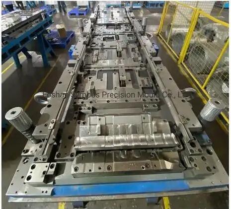
Stamping Dies Exposed: From Raw Steel To Precision Parts
What Are Stamping Dies and Why They Matter in Manufacturing
Ever wonder how your car's body panels, smartphone components, or kitchen appliances get their precise shapes? The answer lies in stamping dies—precision-engineered tooling systems that transform flat sheet metal into complex three-dimensional parts through controlled deformation. Understanding what is metal stamping and how these specialized tools work is essential for anyone involved in manufacturing, procurement, or quality management.
A stamping die is a special, one-of-a-kind precision tool that cuts and forms sheet metal into a desired shape or profile. This cold-forming process uses high-pressure presses to shape molded metal parts without introducing heat intentionally. The result? Consistent, repeatable parts produced at speeds reaching up to 1,500 cycles per minute with tolerances as tight as ±0.001 inches.
The Anatomy of a Stamping Die System
What are dies made of, and how do they work together? Every stamping die consists of several critical components working in harmony:
- Punch (Male Component): The upper tool that descends into the die block, imparting the desired shape through cutting or forming operations. Punches are typically made from hardened tool steel to withstand high wear.
- Die Block (Female Component): The lower cavity that mirrors the punch shape, receiving the material and completing the forming or cutting action. For cutting operations, the die block is offset slightly larger than the punch to allow proper clearances.
- Stripper System: Usually spring-driven, this component pulls or strips the material off the punches after each press cycle completes, allowing continuous operation.
- Guide Pins and Bushings: These critical components maintain precise alignment between the upper and lower die halves, ensuring consistent part quality with every stroke.
- Die Shoes: The base plates—typically cast iron or steel—where all other die components are attached. They must resist deflection during operation.
How Dies Transform Raw Material into Precision Parts
What is stamping at its core? It's a fascinating interplay of force, precision, and material science. When the press activates, the punch descends toward the die block with tremendous force. The sheet metal positioned between them experiences controlled deformation—either cutting through shearing action or forming into the desired shape.
During cutting operations, the metal is stressed to the point of failure between bypassing tool steel sections. The gap between punch and die—called cutting clearance—is typically about 10 percent of the metal's thickness. This produces a characteristic cut edge with a shiny "cut band" and a rougher "fracture zone."
Forming operations work differently. Instead of severing the material, the punch and die work together to stretch, bend, or draw the metal into three-dimensional shapes. What is die manufacturing expertise really about? It's understanding exactly how different materials behave under these forces and designing tooling that accounts for material springback, thinning, and flow characteristics.
Why Die Quality Determines Part Quality
Here's a reality check: your stamped parts can only be as good as the dies producing them. Every surface finish, dimensional tolerance, and edge condition traces directly back to tooling quality. Consider these connections:
- Precision translates to consistency: Well-engineered dies produce identical parts across millions of cycles
- Material selection impacts longevity: Tool steel grades and surface treatments determine how long dies maintain accuracy
- Design expertise reduces defects: Proper clearances, pilot configurations, and stripping mechanisms prevent burrs, dimensional drift, and surface damage
For procurement professionals, this means evaluating tooling investments differently. The upfront cost of a stamping die represents just one piece of the total cost equation. What is dies in manufacturing terms really worth? Consider the per-part cost across the entire production run, maintenance requirements, and the quality outcomes that affect your downstream operations and customer satisfaction.
In high-volume environments—automotive, electronics, appliance manufacturing—where consistency and repeatability are paramount, understanding die fundamentals isn't optional. It's the foundation for smart procurement decisions, predictable quality outcomes, and effective cost management throughout your product's lifecycle.
Types of Stamping Dies and Their Industrial Applications
With so many stamping die options available, how do you know which type fits your manufacturing needs? The answer depends on understanding three overlapping classification systems that the industry uses to categorize dies and stamping operations. Let's break down each framework so you can make informed decisions about tooling investments.
Dies and stamping technologies have evolved significantly, creating specialized solutions for virtually every production scenario. Whether you're producing simple flat washers or complex automotive structural components, there's a die configuration designed for your specific requirements.
Operational Classification: What Each Die Type Accomplishes
The first way to classify metal stamping dies is by the operation they perform. Think of this as understanding what the die actually does to your material:
- Blanking Dies: These cut the outer profile of your part from the sheet metal. The blanked piece becomes your finished part (or progresses to additional operations), while the remaining material becomes scrap.
- Piercing Dies: The opposite of blanking—these create internal holes, slots, or cutouts. The pierced material becomes scrap while the surrounding sheet remains as the workpiece.
- Forming Dies: Rather than cutting, these plastically deform the metal into three-dimensional shapes without changing material thickness significantly. Think of embossing, coining, or creating ribs and stiffening features.
- Drawing Dies: These stretch metal into cup-like or hollow shapes through a process called deep drawing. Soda cans, cookware, and automotive fuel tanks are classic examples of drawn parts.
- Bending Dies: These create angular shapes along defined bend lines, producing brackets, channels, and various formed profiles. Springback compensation is critical in bending die design.
In practice, many sheet metal dies combine multiple operations. A single tooling setup might pierce pilot holes, blank an outer profile, and form stiffening ribs—all within one press cycle or across sequential stations.
Single-Station vs Multi-Station Die Configurations
The second classification framework focuses on how production occurs. Imagine you need a part with three holes, a bent flange, and a specific outer shape. You have two fundamental approaches:
Single-station dies perform one operation per press stroke. If your part requires five operations, you'll either need five separate die setups (with manual or automated part handling between them) or a more sophisticated die configuration. These dies work well for:
- Low-volume production runs where tooling investment must stay minimal
- Simple parts requiring only one or two operations
- Prototyping and development where design changes are frequent
- Situations where flexibility outweighs production speed
Within single-station dies, you'll encounter several subtypes. Simple dies perform exactly one operation per stroke—straightforward blanking or piercing, for example. Compound dies step up complexity by performing multiple cutting operations simultaneously in a single stroke, such as blanking an outer profile while piercing internal holes at the same time. Combination dies take this further by combining both cutting and forming operations within one stroke.
Multi-station dies move the workpiece through multiple stations, each performing different operations in sequence. This approach dominates high-volume manufacturing because it dramatically increases throughput while reducing handling between operations.
Progressive Dies for High-Volume Continuous Production
Progressive die stamping represents the workhorse of modern high-volume manufacturing. Here's how it works: a continuous metal strip feeds through the die, advancing a fixed distance (called the "pitch") with each press stroke. Each station in the die performs a specific operation, and by the time the strip reaches the final station, the completed part is cut free.
The mechanics are elegant in their efficiency:
- The metal coil feeds into straighteners and feeders that ensure consistent positioning
- Pilot holes punched early in the sequence engage with pilot pins at each subsequent station, maintaining precise alignment
- Each press stroke simultaneously advances all parts in progress—one part blanks out while others undergo forming, piercing, or trimming operations upstream
- Finished parts drop through or are ejected, ready for secondary operations or assembly
Progressive dies excel when you need high-volume production of relatively small parts with multiple features. According to industry references, these dies enable extremely high production rates with exceptional repeatability once tooling is optimized. The tradeoff? Higher upfront tooling costs and reduced flexibility for design changes.
Transfer Dies for Complex Geometry Requirements
What happens when your part is too large for progressive stamping, requires deep drawing, or needs operations that can't be performed while attached to a strip? That's where transfer die stamping enters the picture.
In transfer operations, the part is cut from the sheet metal at the beginning rather than the end. Individual blanks then move between stations—either through mechanical transfer systems, robotics, or in some cases manual handling. This approach suits:
- Large structural components like automotive body panels and frames
- Parts requiring deep draws where the strip attachment would interfere
- Complex geometries needing repositioning between operations
- Tube and shell forming where workpiece handling differs from flat stamping
Transfer die systems can consist of a single large die with multiple stations or a series of individual dies arranged in a production line. The key distinction from stamping and die cutting in progressive systems is that workpieces move independently rather than remaining attached to a carrier strip.
Tooling Class System: Matching Investment to Volume
The third classification framework addresses build quality and expected production life. Industry professionals often reference Class A, Class B, and Class C tooling:
- Class A Dies: Built for the highest production volumes (typically millions of cycles), featuring premium tool steels, carbide inserts where appropriate, and precision construction throughout. These represent the highest tooling investment but deliver the lowest per-part cost at scale.
- Class B Dies: Designed for medium production volumes, balancing durability with cost. Suitable for programs expecting hundreds of thousands of parts over the tooling lifetime.
- Class C Dies: Appropriate for low-volume production, prototyping, or bridge tooling. Lower initial investment, but may require more frequent maintenance or replacement.
Comprehensive Die Type Comparison
The following table summarizes key characteristics to help you match die configurations to your specific requirements:
| Die Type | Typical Applications | Production Volume Suitability | Relative Tooling Investment | Key Advantages |
|---|---|---|---|---|
| Simple Single-Station | Basic blanking, piercing, simple bends | Low to medium (prototypes to 50K parts) | Low | Flexibility, quick changeover, low cost |
| Compound | Flat parts with holes, washers, gaskets | Medium (10K to 500K parts) | Low to moderate | Multiple cutting operations in one stroke |
| Combination | Parts requiring cutting and forming together | Medium (10K to 500K parts) | Moderate | Cutting plus forming in single stroke |
| Progressive | High-volume small to medium parts with multiple features | High (100K to millions) | High | Maximum throughput, excellent repeatability |
| Transfer | Large parts, deep draws, complex structural components | Medium to high (50K to millions) | High | Handles complexity progressive cannot |
Selecting the right die type involves balancing production volume against tooling investment, part complexity against cycle time requirements, and flexibility needs against per-part cost targets. As you'll see in the following sections, understanding die components and design principles helps refine these decisions further.
Essential Stamping Die Components and Design Principles
Now that you understand the different die types available, let's go deeper into what makes these tools actually work. Whether you're evaluating a supplier's proposal or troubleshooting production issues, understanding stamping die components and their design principles gives you the knowledge to ask the right questions and make better decisions.
Every stamp die consists of carefully engineered elements working in concert. When any component falls short—whether through poor design, incorrect specification, or inadequate maintenance—the entire system suffers. Here's what you need to know about each critical element:
- Punch: The male cutting or forming tool that descends into the die block, creating the desired feature through shearing or plastic deformation
- Die Block: The female cavity that receives the punch and provides the opposing cutting edge or forming surface
- Stripper Plate: Holds material flat during the cutting stroke and strips it from the punch on the return stroke
- Pilots: Precision pins that locate the strip accurately at each station in progressive operations
- Guide System: Pins and bushings that maintain alignment between upper and lower die halves
- Backing Plates: Hardened plates that support punches and die inserts, distributing forces to prevent damage
- Die Shoes: The foundation plates that hold all components in proper relationship
Punch and Die Block Engineering Fundamentals
Think of the punch and die block as dance partners—their relationship must be precisely choreographed for successful metal stamping die design. The punch geometry determines the feature being created, while the die block provides the essential counterform that completes each operation.
Punch Design Considerations: The punch tip geometry varies based on the intended operation. Cutting punches typically feature flat faces for clean shearing, though shear angles on the punch face can reduce tonnage by 25-50% by concentrating cutting forces on a smaller area at any given moment. Forming punches require carefully calculated radii and surface finishes to control material flow without creating stress risers or surface defects.
Wear characteristics demand particular attention in metal stamping die design. Small punches wear faster than larger ones simply due to higher stress concentration. Sharp corners show wear more quickly than curved or straight edges. Any portion of the punch that contacts material first—such as the leading edge of a shear face—does the most work and requires more frequent inspection.
Die Block Specifications: The die block (sometimes called the matrix) is truly the cornerstone of the stamping system—the ultimate judge of product quality. Cavity design must account for material flow during forming operations, slug ejection in cutting operations, and appropriate relief angles to prevent slug packing.
Surface finish requirements in the die process vary by application. Cutting cavities benefit from polished surfaces that reduce friction during slug passage. Forming cavities require specific textures—too rough causes scoring; too smooth can lead to wrinkling in drawing operations. Most manufacturers specify surface finishes between 16 and 32 microinches Ra for cutting operations, with tighter control for critical forming applications.
Stripper Systems and Their Impact on Production Speed
After each press stroke, the material tends to cling to the punch. Without effective stripping, you can't achieve continuous operation. But stripper design involves tradeoffs that directly affect part quality, cycle time, and tooling cost.
Spring Strippers represent the premium choice for most applications. According to technical references, spring strippers hang below the punch tips and are among the first components to contact the part, keeping it fixed throughout the cycle. Their continuous pressure during the working stroke improves:
- Part flatness by holding material firmly against the die surface
- Cut quality through consistent material support
- Strip alignment by preventing movement during operations
- Overall tool life by controlling snap-through forces
The main considerations with spring strippers involve proper spring selection and avoiding over-entry. Closing the die below the recommended shut height causes spring damage, pre-piercing of holes, and potential tool breakage.
Fixed Strippers offer a simpler, lower-cost alternative—essentially a steel plate with clearance holes mounted in a fixed position. As the die opens, the stripper holds material down and removes it from the punches. However, fixed strippers have notable drawbacks: they cannot support material during the cutting cycle, and the snap-thru shock when punches suddenly break through material can cause damage to punch heads.
Hydraulic Strippers find application in heavy-duty or specialized forming operations where spring forces cannot provide sufficient control. They offer adjustable pressure and timing but add complexity and cost. For standard sheet metal die applications, spring strippers typically provide the best balance of performance and economics.
Urethane Strippers provide a cost-effective solution for simpler applications. They press-fit onto punches to prevent them from falling into the die. However, urethane compresses significantly under load and may not maintain consistent part flatness—making them less suitable for precision work.
Clearance Calculations for Different Material Types
Here's where stamping die design becomes genuinely technical—and where many quality problems originate. Clearance refers to the gap between the punch and die block when the punch enters the die opening. Get this wrong, and you'll see burrs, excessive wear, poor hole quality, or all three.
The fundamental principle: total die clearance should typically equal 15-30% of material thickness, varying by material type and operation. This means clearance per side runs approximately 7.5-15% of material thickness—or roughly 5-10% per side for many common applications.
According to industry technical guides, recommended clearances vary significantly by material:
| Material Type | Material Thickness | Piercing Total Clearance | Blanking Total Clearance |
|---|---|---|---|
| Aluminum (25,000 psi shear) | Less than 0.098" (2.50mm) | 15% | 15% |
| Aluminum | 0.098" to 0.197" (2.50-5.00mm) | 20% | 15% |
| Mild Steel (50,000 psi shear) | Less than 0.118" (3.00mm) | 20% | 15% |
| Mild Steel | 0.118" to 0.237" (3.00-6.00mm) | 25% | 20% |
| Stainless Steel (75,000 psi shear) | Less than 0.059" (1.50mm) | 20% | 15% |
| Stainless Steel | 0.059" to 0.157" (1.50-4.00mm) | 25-30% | 20% |
What happens with incorrect clearances? The consequences are predictable:
- Clearance too small: Secondary shear cracks form in the material, dramatically increasing punching force and accelerating tool wear. You'll see reduced tool life, galling problems, and excessive heat buildup.
- Clearance too large: The fracture planes don't meet cleanly, producing rough edges, increased burr height, and poor dimensional control. Parts may show excessive rollover and rounded profiles.
Your die stamps tell the story. Examining slugs reveals whether clearance is correct: an ideal slug shows fracture planes from top and bottom meeting in alignment. If the burnish zone is too small with a rough fracture plane, clearance is excessive. If fracture planes show little angle with an oversized burnish zone, clearance is too tight.
Pilot Configurations for Strip Positioning: In progressive operations, pilots ensure accurate positioning at each station. These precision pins enter previously punched holes before operations begin at downstream stations. The pilot point diameter is typically 0.001" smaller than the punch diameter used to create the locating hole, preventing sticking during entry while maintaining accurate positioning.
Proper pilot design and timing are critical. Pilots should fully engage the strip before forming or cutting operations commence. For most applications, pilot working lengths extend 0.080" to 0.125" beyond perforating punches to ensure strip capture before operations begin. This attention to stamping die components and their precise relationships distinguishes reliable production tooling from problematic setups requiring constant adjustment.
Die Materials and Tool Steel Selection Criteria
You've learned about die types and components—but what are these critical tools actually made of? The answer directly impacts how long your steel stamping dies will last, how often they'll need maintenance, and ultimately what your parts will cost. Yet surprisingly, many buyers overlook material selection when evaluating tooling proposals. Let's fix that.
Tool steel selection for dies in manufacturing isn't a one-size-fits-all decision. The right choice depends on your production volume, the material you're stamping, the operations being performed, and your tolerance for maintenance intervals. Understanding these relationships helps you make smarter investments and avoid costly tooling failures.
Tool Steel Grades for Different Production Demands
Four primary tool steel families dominate the stamper dies industry, each engineered for specific performance characteristics. Here's what you need to know about each:
D2 Tool Steel: This is the standard choice for long-life blanking dies requiring exceptional wear resistance. With a working hardness of 58-60 HRC, D2 strikes an excellent balance between durability and dimensional stability. It's particularly effective in high-strength stamping applications where edge retention matters. However, D2's toughness is inferior to low-alloy steels—meaning it performs best in applications without severe impact loading.
A2 Tool Steel: Think of A2 as the versatile middle-ground option. This medium-alloy air-hardening steel offers toughness superior to the D series and wear resistance better than the O series. A2 excels in medium-batch stamping dies and punches requiring hardness between 58-60 HRC. Its exceptional dimensional stability during heat treatment makes it particularly reliable for precision applications where minimal distortion is critical.
S7 Tool Steel: When impact resistance becomes your primary concern, S7 delivers. This air-quenching steel combines high toughness with dimensional stability, making it ideal for heavy-duty blanking dies and shearing tools. S7 withstands extremely high impact loads at a typical hardness of 54-58 HRC. For die stamping applications involving thick plates or repeated shock loading, S7 often outperforms harder but more brittle alternatives.
M2 High-Speed Steel: For the most demanding operations—especially when stamping difficult materials like stainless steel—M2 provides superior performance. This molybdenum-based high-speed steel maintains a stable working hardness of 60-65 HRC and offers superior edge-chipping resistance compared to D-series steels. M2 is highly suitable for long-life dies exceeding 100,000 cycles and excels in high-speed stamping applications.
| Tool Steel Grade | Working Hardness (HRC) | Primary Strength | Best Applications | Relative Cost |
|---|---|---|---|---|
| D2 | 58-60 | Wear resistance, edge retention | High-volume blanking, long-run production | Moderate |
| A2 | 58-60 | Balanced toughness and wear resistance | Medium-batch dies, precision applications | Moderate |
| S7 | 54-58 | Impact resistance, shock loading | Heavy-duty blanking, thick plate stamping | Moderate-High |
| M2 | 60-65 | Red hardness, edge-chipping resistance | Stainless steel, high-speed operations | High |
Matching Steel to Production Volume: Your expected production run significantly influences material selection. For short runs under 10,000 pieces, focus on controlling material and machining costs with low-alloy steels like O1 or surface-hardened steel. Medium runs of 10,000 to 100,000 pieces justify A2 steel's balance of performance and cost. For high-volume manufacturing die applications exceeding 100,000 pieces, D2 becomes the standard—with M2 or carbide inserts for the most demanding conditions.
When Carbide Inserts Justify the Investment
Carbide offers dramatically longer life than even premium tool steels—but at significantly higher cost. When does the investment make sense? Consider carbide inserts when:
- Production volumes reach the millions: Carbide cutting and forming inserts last significantly longer than standard tool steels, making them economically justified at high volumes where the extended service life offsets initial cost
- Stamping highly abrasive materials: High-silicon electrical steel, stainless steel, and other abrasive materials accelerate wear dramatically. Carbide's superior hardness extends die life in these challenging applications
- Downtime costs exceed tooling costs: In continuous production environments where every minute of press downtime carries significant cost, carbide's extended maintenance intervals deliver real value
- Part tolerances demand consistency: Carbide maintains dimensional accuracy longer than tool steel, reducing the drift that occurs as cutting edges wear
For dies manufacturing at Class A production levels—typically millions of cycles—carbide inserts in critical wear areas often represent the most economical choice despite higher upfront investment. However, carbide's brittleness compared to tool steel means it's unsuitable for applications with significant shock loading. In thick-plate stamping where impact loads increase significantly, M2 demonstrates more reliable toughness performance than carbide.
Surface Treatments That Extend Die Service Life
Beyond base material selection, surface treatments can dramatically extend die life and improve part quality. Three primary approaches dominate the manufacturing die industry:
Ion Nitriding: Many stamping operations are shifting away from standard chrome plating in favor of ion nitriding. Unlike chrome's surface bonding, nitriding relies on nitrogen diffusion into the steel surface, forming a metallurgical bond with greater strength and durability. The process heats die components to approximately 950°F in a nitrogen-enriched atmosphere, where nitrogen forms compounds with alloying elements to yield extreme hardness (>58 HRC) and excellent wear and fatigue resistance. Case depths range from 0.0006 to 0.0035 inches depending on application requirements.
A key advantage of nitriding: unlike coatings, this substrate treatment still allows toolmakers to work the punch, cavity, and binder surfaces after treatment to improve surface condition.
PVD (Physical Vapor Deposition) Coatings: This vacuum deposition method applies thin films to die surfaces at relatively low temperatures—around 420°F for deposition with processing temperatures of 750°F. Common PVD coating chemistry includes chromium nitride (CrN) at thicknesses of 1-4 microns. Benefits include chemical and heat resistance, increased hardness, high wear resistance, improved lubricity, and a low coefficient of friction (0.5). The low processing temperatures minimize part distortion—a critical consideration for precision tooling.
Standard industrial PVD coatings include titanium nitride (TiN), titanium carbonitride (TiCN), chromium nitride (CrN), and diamond-like carbon (DLC)—each offering specific advantages for different applications.
Chrome Plating: The traditional approach still finds application where cost constraints or specific surface requirements favor it. Chrome provides good wear resistance and a smooth surface finish. However, its surface-bonding mechanism (versus nitriding's diffusion) means it may be less durable under the most demanding conditions.
Material selection isn't just about initial tool cost—it's about total cost of ownership across the entire production run, including maintenance intervals, sharpening cycles, and eventual replacement.
The connection between die in manufacturing material choices and total cost becomes clear when you calculate expected die life. A D2 die requiring sharpening every 50,000 hits might seem less expensive than an M2 die initially—but if M2 extends that interval to 150,000 hits, the reduced maintenance cost and downtime often justify the premium. For high-volume programs, these calculations should drive your material specification decisions rather than simple upfront cost comparisons.
With the right combination of base material and surface treatment, your tooling investment delivers consistent quality across millions of cycles. But even the best materials require proper design—which is where modern CAE simulation and digital design tools transform the die development process.
Modern Die Design Technology and CAE Simulation
Imagine discovering a critical forming defect only after investing thousands of dollars in tooling and weeks of manufacturing time. That's the traditional reality of die development—and it's exactly what modern stamping technology has transformed. Today's digital design workflows predict problems before any steel is cut, dramatically reducing development costs and accelerating time-to-production.
The shift from trial-and-error toolmaking to simulation-driven development represents one of the most significant advances in the metal stamping process. According to industry analysis, part and process design defects often emerge only during the first trials in the try-out stage of die manufacturing—when corrections are both time-consuming and costly. Virtual tryout capabilities now address these challenges before physical tooling exists.
CAE Simulation for Defect Prediction and Prevention
Computer-Aided Engineering simulation has become the cornerstone of modern metal stamping techniques. But what exactly does CAE predict, and how does it transform the development process?
Sheet metal forming simulation software analyzes how material behaves under forming conditions—predicting where problems will occur and enabling design optimization before physical production begins. Key capabilities include:
- Material Flow Analysis: Simulation tracks how sheet metal moves during forming operations, identifying areas of excessive stretch, compression, or shear that could cause failures
- Springback Prediction: Advanced high-strength steels and aluminum alloys exhibit significant springback after forming. CAE quantifies this rebound, enabling compensatory die geometry adjustments
- Thinning and Thickening Maps: Finite element analysis reveals where material will thin excessively (risking tears) or thicken (causing wrinkles and surface defects)
- Wrinkling and Surface Defect Detection: Simulation identifies aesthetic defects that would otherwise appear only during physical try-out—critical for visible automotive components
The stamping metal process involves continuous interaction between sheet metal and dies, with material selection presenting particular challenges. Advanced high-strength steels and aluminum alloys—increasingly common in automotive applications—are challenging to form and exhibit high springback magnitudes. Virtual simulation enables engineers to optimize die compensation strategies for these demanding materials before committing to physical tooling.
Strip Layout Optimization for Material Efficiency
In progressive die operations, strip layout directly impacts both material cost and part quality. Modern CAD/CAM systems optimize this critical aspect of the sheet metal stamping process through sophisticated algorithms that balance competing requirements.
Effective strip layout optimization addresses several key factors:
- Material Utilization: Minimizing scrap by optimizing part orientation, nesting, and carrier strip dimensions—often achieving material savings of 5-15% compared to non-optimized layouts
- Pilot Hole Positioning: Ensuring accurate strip advancement through proper pilot location relative to part features and forming operations
- Station Sequencing: Arranging operations to maintain strip stability, manage forces, and prevent interference between adjacent stations
- Carrier Strip Design: Balancing strip width (cost) against structural integrity needed to carry parts through multiple stations
The aluminum stamping process presents unique layout challenges due to the material's lower strength and higher tendency to deform during handling. Simulation tools model strip behavior under feeding forces, identifying potential positioning errors before they translate into production problems.
From Digital Design to Production-Ready Tooling
The modern die design workflow integrates CAD modeling, CAE simulation, and CAM programming into a seamless digital thread. Here's how this process transforms development timelines:
Traditional Approach: Design → Build → Test → Identify Defects → Modify → Rebuild → Retest (often multiple iterations)
Simulation-Driven Approach: Design → Simulate → Optimize → Build → Validate (typically one or two iterations)
This shift delivers measurable benefits. Achieving optimal stamping conditions traditionally required fine-tuning parameters like press speed, blank holder force, and lubrication through extensive testing—a time-consuming process. Virtual testing compresses this optimization into days rather than weeks.
Additionally, simulation addresses material variation challenges. Even within the same batch, material property inconsistencies can impact eventual part quality. CAE enables sensitivity analysis—testing how design performs across the expected range of material properties—before production begins.
Virtual die try-out capabilities have fundamentally changed the economics of tooling development, reducing iterations and enabling first-pass success rates that were impossible with traditional trial-and-error methods.
For manufacturers seeking these advanced capabilities, working with suppliers who invest in simulation technology delivers tangible advantages. Shaoyi's precision stamping die solutions leverage advanced CAE simulation to achieve a 93% first-pass approval rate—dramatically reducing development time and cost. Their engineering team combines IATF 16949-certified quality systems with rapid prototyping capabilities as fast as 5 days, delivering production-ready tooling tailored to OEM standards. Explore their comprehensive mold design and fabrication capabilities to see how simulation-driven development accelerates your production timeline.
Understanding how simulation capabilities translate into practical die selection decisions helps you specify the right tooling configuration for your specific requirements—which we'll address next.
How to Select the Right Stamping Die Configuration
You understand die types, components, materials, and design technology—but how do you translate that knowledge into the right tooling decision for your specific project? Selecting the optimal stamping die configuration requires balancing multiple factors simultaneously. Get this decision right, and you'll achieve cost-effective production with consistent quality. Get it wrong, and you'll either overpay for tooling you don't need or struggle with inadequate tooling that can't meet your requirements.
The good news? A structured decision-making framework cuts through the complexity. Whether you're specifying tooling for a new product launch or evaluating proposals from die manufacturers, these guidelines help you match your requirements to the right die configuration.
Volume-Based Die Selection Guidelines
Annual production volume serves as the primary driver for die selection decisions. Why? Because the die for press operations represents a fixed investment that gets amortized across every part produced. Higher volumes justify greater tooling investment because the per-part tooling cost drops dramatically as production quantities increase.
According to industry analysis, here's how volume thresholds typically align with die configurations:
- Under 10,000 parts annually: Single-station or line dies often make the most economic sense. Tooling costs stay low, and the flexibility to accommodate design changes provides additional value during early product lifecycles
- 10,000 to 100,000 parts annually: This middle ground requires careful break-even analysis. Progressive dies may justify their higher investment if per-part savings exceed the tooling cost delta over your production horizon
- Over 100,000 parts annually: Progressive dies typically deliver the lowest per-part cost, and their higher initial investment is recovered relatively quickly through production efficiency
- Multi-million part programs: Class A progressive tooling with premium materials and carbide inserts becomes economically justified at these volumes
The break-even calculation is straightforward: if the per-part savings from a progressive die versus line tooling equals a certain amount, and the tooling cost difference is known, then dividing the tooling delta by per-part savings gives you the break-even quantity. Beyond that point, progressive wins on economics.
Matching Die Complexity to Part Requirements
Volume alone doesn't tell the whole story. Part geometry and complexity often override pure volume considerations when selecting between metal stamping presses and die configurations. Ask yourself these questions:
Can your part stay attached to a carrier strip? This is the fundamental question separating progressive from transfer die applications. Progressive stamping keeps parts connected to the strip throughout all operations. If your part requires deep draws that would interfere with strip movement, or features tall walls that collide with carriers, transfer tooling becomes necessary regardless of volume.
How many operations does your part require? Simple parts needing only blanking or basic piercing can run efficiently in single-station dies. As operation counts increase—pierce, form, bend, coin, trim—progressive dies consolidate these steps into one continuous process. For complex parts requiring 10 or more stations, progressive die stamping delivers significant efficiency advantages.
What are your tolerance requirements? Tighter tolerances generally favor progressive dies because the part maintains consistent positioning throughout all operations. Transfer systems introduce potential positioning variation each time the part moves between stations—though modern servo-driven transfer mechanisms have narrowed this gap considerably.
Metal stamping and forming operations for complex geometries often require careful sequencing. Consider these geometry-driven guidelines:
- Flat parts with holes: Compound or simple progressive dies handle these efficiently
- Parts with bends and forms: Progressive dies excel, with forming operations sequenced after piercing
- Deep-drawn shells or cups: Transfer dies provide necessary draw and redraw capabilities
- Large structural components: Transfer or line dies accommodate oversized parts that exceed progressive strip handling limits
Material Considerations for Die Selection
The material you're stamping significantly influences die configuration requirements. Different alloys present distinct forming challenges that affect both die design and process selection.
Aluminum alloys present unique challenges. Their lower strength compared to steel means carrier strips must be wider to maintain rigidity during progressive operations. Springback is pronounced, often requiring restrike stations or over-bend compensation. For deep-drawn aluminum components like battery enclosure cups, transfer dies with draw-redraw-trim-pierce sequences typically deliver better results than attempting progressive strip feeding.
High-strength steels demand higher tonnage and more robust tooling. These materials may push you toward transfer or staged line operations to control cracking that could occur if forming is attempted too aggressively in progressive strip operations. The forming limits of advanced high-strength steels require careful process planning—simulation becomes particularly valuable for these applications.
Stainless steel requires attention to galling prevention. Progressive dies can handle stainless effectively with proper lubrication and surface treatments, but deep-formed stainless components often benefit from transfer die configurations.
Standard carbon steel and galvanized materials (0.5-3.0mm thickness) work well across all die configurations, making volume and complexity the primary decision drivers for these common materials.
Decision Framework: Selecting Your Die Configuration
Use this step-by-step process to work through your die selection decision systematically:
- Define your annual volume requirements and forecast horizon. Include ramp-up quantities from prototype through full production. Consider whether volumes might scale significantly over the product lifecycle
- Analyze part geometry for strip compatibility. Can the part ride a carrier strip through all operations? Are there deep draws, tall features, or complex 3D forms that would interfere with progressive feeding?
- Count required operations. List every pierce, blank, form, bend, coin, and trim operation. More operations generally favor progressive or transfer over single-station approaches
- Evaluate material characteristics. Note thickness, alloy type, and any special forming considerations like springback compensation or galling prevention
- Assess tolerance and quality requirements. Tighter tolerances may require more sophisticated die configurations with better positional control
- Calculate break-even points. Compare tooling investment differences against per-part cost savings at your projected volumes
- Match to available press equipment. Ensure selected die configurations are compatible with your sheet metal stamping press capabilities
Press Compatibility Requirements for Die Specifications
Your die selection must align with available die-stamping machine capabilities. Even the perfect die design fails if your press can't run it effectively. Key compatibility factors include:
Tonnage Requirements: Calculate the total force needed for all operations occurring simultaneously. For progressive dies, this means summing forces across all active stations. Your press should have capacity exceeding this requirement by a reasonable margin—typically 20-30%—to account for material variation and provide operational headroom.
Bed Size: The die must fit within your press bed dimensions with adequate clearance for strip feeding, part ejection, and maintenance access. Progressive dies for complex parts can become quite large, potentially requiring dedicated presses.
Stroke Length: Ensure sufficient stroke for your deepest forming operations plus clearance for strip feeding and part removal. Deep-draw applications in transfer operations may require significantly longer strokes than typical blanking and piercing work.
Shut Height: Verify your press can accommodate the closed die height. This becomes particularly important when retrofitting dies into existing equipment or running multiple die configurations on the same press.
Feed System Compatibility: Progressive dies require servo or mechanical feeding systems capable of precise pitch advancement. Verify feed accuracy meets your tolerance requirements and that feed length capacity accommodates your strip layout.
| Selection Factor | Favors Single-Station/Line | Favors Progressive | Favors Transfer |
|---|---|---|---|
| Annual Volume | Under 10,000 parts | Over 50,000 parts | Medium-high with complexity |
| Part Size | Large or oversized | Small to medium | Medium to large |
| Geometry | Simple, few operations | Multiple features, flat profile | Deep draws, 3D complexity |
| Design Stability | Frequent changes expected | Stable, proven design | Stable design |
| Tooling Budget | Constrained | Investment justified by volume | Investment justified by complexity |
| Lead Time | 2-8 weeks | 10-16 weeks | 12-20+ weeks |
Remember that these guidelines represent starting points rather than rigid rules. Many successful programs begin with simpler tooling for prototype and pilot phases, then transition to progressive or transfer dies as volumes scale—a practical approach that validates demand before committing to higher tooling investments. Your sheet metal press die selection should align with both current requirements and anticipated future needs.
With the right die configuration selected, maintaining that tooling becomes critical to sustaining quality and productivity over the production lifecycle—which brings us to essential maintenance and troubleshooting practices.
Stamping Die Maintenance and Troubleshooting Essentials
You've invested significantly in precision stamping tooling—but that investment only pays off if your dies deliver consistent quality throughout their service life. Unfortunately, many manufacturers treat maintenance as an afterthought, responding only when problems become impossible to ignore. This reactive approach leads to unplanned downtime, quality escapes, and premature die replacement. Let's change that perspective.
According to industry maintenance experts, leading manufacturers have redefined stamping tool and die maintenance as a strategic business driver rather than an unavoidable expense. Every dollar saved through exceptional maintenance—whether by avoiding downtime, reducing scrap, or postponing major capital investments—has the same impact on the bottom line as earning an additional dollar in net profit.
Recognizing Die Wear Patterns Before Quality Suffers
Your stamp dies tell you when they're struggling—if you know what to look for. The key is catching wear patterns before they translate into defective stamped parts. Think of inspection as preventive medicine: early detection prevents costly failures.
Effective wear pattern recognition starts with understanding where problems originate. Recognizing the direct relationship between a component's role and its likely failure modes is the bedrock of smart, proactive maintenance. If galling appears, the solution isn't simply to polish the tool—it's to examine the lubrication system, evaluate material compatibility, and assess surface treatment.
Critical Inspection Points:
- Cutting Edge Condition: Look for chipping, rounding, or built-up material on punch tips and die button edges. Sharp edges produce clean cuts; degraded edges create burrs and rough fracture zones
- Surface Finish Changes: Scoring, galling marks, or polished wear patterns indicate friction issues that will worsen without intervention
- Dimensional Checks: Measure critical punch diameters and die openings against original specifications. Wear typically appears as undersized punches and oversized die openings
- Guide System Play: Check for excessive clearance in guide pins and bushings that allows upper and lower die halves to shift during operation
- Stripper System Function: Verify spring tension and stripper plate flatness—worn springs or damaged strippers affect part quality and strip feeding
Sharpening vs. Replacement Decision: When should you sharpen and when should you replace? The answer depends on remaining tool material and defect type. Light edge rounding or minor chipping typically responds well to sharpening—removing only the minimum material necessary to restore a sharp edge. However, deep chipping, cracking, or significant dimensional loss may require replacement. A useful guideline: if sharpening would remove more than 10-15% of the original punch working length, evaluate replacement economics.
Preventive Maintenance Schedules by Production Volume
Sounds complex? It doesn't have to be. A structured maintenance schedule transforms die processing from reactive firefighting into predictable, manageable routine. The key is matching maintenance intensity to production demands.
According to maintenance protocol frameworks, world-class programs break into four advancing tiers:
Tier 1 - Daily Operator Checks (Every Shift): This 5-minute inspection catches over 80% of potential failures before they escalate. Operators check for obvious damage, verify lubrication, and confirm proper strip feeding. The non-negotiable principle: never operate a compromised tool.
Tier 2 - Preventive Maintenance (By Stroke Count):
| Production Volume | Recommended Interval | Key Actions |
|---|---|---|
| Light-duty (under 50,000 strokes) | Monthly or at job completion | Clean, inspect, lubricate, document |
| Medium-duty (50,000-250,000 strokes) | Every 50,000-100,000 strokes | Above plus dimensional checks, sharpening as needed |
| High-volume (over 250,000 strokes) | Every 25,000-50,000 strokes | Full inspection, component replacement, precision measurements |
Tier 3 - Diagnostic Intervention: When preventive checks reveal abnormal trends, shift to investigative problem-solving. Advanced techniques include precision measurements, wear pattern analysis, and root cause investigation.
Tier 4 - Major Overhaul: Comprehensive rebuilds addressing accumulated wear across all components—typically scheduled annually or at manufacturer-recommended intervals.
Storage and Handling: Proper die storage extends service life and prevents damage between production runs. Store dies in climate-controlled areas to prevent corrosion. Apply rust preventive coatings on all working surfaces. Support dies properly to prevent distortion from their own weight. Document storage location and condition for easy retrieval.
Troubleshooting Common Stamping Defects
When die stamped parts show quality problems, systematic troubleshooting identifies the root cause faster than random adjustments. Use this diagnostic approach to connect defect symptoms with their likely die-related causes:
-
Excessive Burrs on Stamped Parts:
- Check punch and die clearances—insufficient clearance creates poor cutting conditions
- Inspect cutting edge sharpness—dull edges push rather than shear material
- Verify proper alignment between punch and die components
-
Dimensional Drift:
- Inspect pilot pins and locating features for wear
- Check guide system for excessive play allowing die halves to shift
- Verify feed accuracy and strip positioning consistency
- Regularly use alignment mandrels to check and adjust machine tool turret alignment
-
Surface Quality Degradation:
- Evaluate lubrication adequacy and distribution
- Inspect die surface condition for galling or scoring
- Check for material buildup on forming surfaces
-
Poor Bending Angles:
- The mold may not be adjusted in place, resulting in angular error
- Insufficient spring elasticity causes poor angles—replace springs
- Material thickness deviation affects bend consistency
- Unreasonable gap settings require repair
-
Inconsistent Wear Patterns:
- Machine tool turret design or processing accuracy may be insufficient
- Upper and lower turntable mounting seat alignment needs verification
- Guide bush precision may have degraded through use
Documentation Matters: Every maintenance intervention—whether replacing a component, taking a measurement, or removing material—should be documented in the tool's maintenance history. This record isn't just administrative paperwork; it's a strategic, high-value data asset that drives optimization of maintenance intervals and serves as the foundation for predictive analysis.
Effective metal stamping tooling management extends beyond reactive repairs to encompass the complete lifecycle—from installation through retirement. When you approach maintenance as an investment rather than a cost, your dies deliver consistent quality across their full service life, and your cost-per-part calculations reflect the true value of well-maintained tooling.
Cost Analysis and ROI Framework for Die Investments
You've evaluated die types, selected materials, and understand maintenance requirements—but how do you translate all this knowledge into smart purchasing decisions? Too often, procurement teams focus solely on the quoted tooling price, missing the larger picture of total cost of ownership. This narrow view leads to budget surprises, unexpected maintenance expenses, and sometimes premature tooling replacement.
Stamping die manufacturing costs aren't arbitrary numbers pulled from thin air. Every quote reflects specific engineering decisions about complexity, materials, and expected service life. Understanding what drives these costs—and what they don't include—positions you to evaluate proposals intelligently and negotiate from a position of knowledge.
Understanding Total Cost of Die Ownership
The purchase price of a custom metal stamping die represents just the starting point. According to industry cost analysis, the overall cost of a die comprises multiple direct and indirect inputs that extend far beyond the initial quote.
Primary Cost Drivers:
- Structural Complexity: More stations, tighter tolerances, and intricate forming operations require additional engineering time and precision machining. A progressive die with 15 stations costs significantly more than a simple compound die—but produces parts at a fraction of the per-piece cost at high volumes
- Die Size: Larger dies require more material, bigger presses for manufacturing, and increased handling challenges. Size also affects shipping and installation logistics
- Material Grade: Tool steel selection directly impacts both initial cost and expected service life. Premium grades like M2 or carbide inserts carry higher upfront costs but deliver extended maintenance intervals
- Tolerance Requirements: Excessively high precision requirements can inflate costs dramatically. If drawings specify ±0.01mm but the actual product allows ±0.05mm, that 0.04mm difference might increase EDM, grinding, and accessory machining costs by 30% to 50%
- Expected Production Life: Dies designed for 1,000,000 cycles require more robust construction than those intended for 100,000 cycles—but over-specifying lifespan wastes investment if production volumes won't materialize
Die cost is not saved; it's designed. Through early design thinking, structural evaluation, and die lifespan simulation, the cost becomes predictable, controllable, and improvable even before manufacturing begins.
Hidden Costs Beyond the Quote:
Several expenses typically fall outside the initial tooling quotation but significantly impact your total investment:
- Trial and Modification Budget: It's almost impossible for a die trial run to achieve perfect dimensions on the first attempt. Reserve 5% to 10% of the total budget as a buffer for trial runs and modifications
- Maintenance and Sharpening: Regular maintenance intervals require toolroom labor, replacement components, and production downtime. These recurring costs accumulate over the die's service life
- Eventual Replacement: Even well-maintained dies eventually wear beyond economical repair. Factor replacement timing into your total cost model
- Storage and Handling: Dies require proper storage between production runs, including climate control, rust prevention, and documentation systems
Break-Even Analysis Between Die Types
When should you invest in more expensive progressive tooling versus simpler single-station dies? The answer lies in break-even analysis—calculating where the higher tooling investment gets recovered through lower per-part production costs.
According to stamping cost analysis, this calculation involves understanding how fixed costs (tooling) and variable costs (per-piece production) interact across different volumes. The mathematics are straightforward: tooling is a fixed cost that gets divided among all your parts. Make 1,000 parts, and that expensive die cost hits each part hard. Make 100,000 parts, and suddenly that tooling investment becomes almost invisible in your per-piece calculation.
Volume Threshold Guidelines:
- Below 10,000 parts: Alternative processes like laser cutting might be more economical than investing in stamping tooling
- 10,000 to 100,000 parts: The decision zone—careful analysis needed to compare tooling amortization against per-part savings
- Above 100,000 parts: Stamping typically delivers the most efficient production economics, with progressive dies often justified despite higher initial investment
The specific break-even point depends on your part's complexity, material costs, and production rate differences between die configurations. Request detailed quotes for multiple approaches and calculate total program cost at your projected volumes—not just initial tooling price.
Evaluating Die Supplier Proposals Effectively
When stamping die manufacturers submit proposals, comparing them requires looking beyond the bottom line. A die for manufacturing success depends on factors that don't always appear prominently in quotations.
Key Evaluation Criteria:
- Lead Time Reality: Compressed schedules often result in rushed engineering or manufacturing shortcuts. Understand what's realistic for your die complexity, and be wary of promises that seem too aggressive
- Design Support Included: Does the quote include design for manufacturability review? Early collaboration can reduce the number of die modifications by over 20% while enhancing overall mass production stability
- Tryout Services: Who performs die tryout, and where? Transportation to distant tryout facilities adds cost and time. On-site capability offers advantages for iteration speed
- Ongoing Technical Support: What happens when you encounter production issues six months after delivery? Evaluate the supplier's responsiveness and maintenance capabilities
- Spare Parts Availability: Will replacement punches, springs, and wear components be available when needed? Some metal stamping die manufacturers provide spare parts lists and maintain inventory for quick replacement
Quote Comparison Framework:
| Evaluation Factor | Questions to Ask | Red Flags |
|---|---|---|
| Die Lifespan Specification | What cycle count is guaranteed before major maintenance? | Vague or missing lifespan commitments |
| Material Specifications | What tool steel grades and heat treatments are included? | Unspecified materials or generic descriptions |
| Precision Guarantees | What tolerances will the die maintain, and for how long? | No precision stability commitments |
| Modification Policy | How are design changes during development handled? | Unlimited change orders at no cost (unrealistic) |
| Maintenance Support | What post-delivery support is included or available? | No ongoing relationship contemplated |
According to industry guidance, dies from quality-focused stamping dies manufacturers are guaranteed to deliver millions of strikes before needing maintenance—but this level of reliability requires appropriate investment. Do not try to cut costs on tooling and die design and manufacturing.
Total Landed Cost Perspective:
Compare total delivered cost rather than just piece price. Include tooling amortization, setup charges, packaging, shipping, and any additional services required. Understanding quote assumptions is critical—different suppliers might make different assumptions about tolerances, inspection requirements, or delivery terms that affect pricing comparability.
Extremely low pricing might indicate misunderstood requirements, inadequate tooling investment, or supplier capability issues. Missing elements in proposals—such as tooling costs, setup charges, or unclear specification assumptions—can lead to cost surprises down the road.
With a clear framework for evaluating die investments and comparing supplier proposals, you're positioned to make informed decisions that optimize total program cost rather than just initial tooling price. Understanding these economics becomes especially critical when addressing the demanding requirements of automotive OEM programs—where quality standards, production volumes, and supplier qualifications all intensify.
Automotive Stamping Dies and OEM Requirements
When you see a flawless car body panel or a perfectly formed structural component, you're witnessing what is stamped metal at its most demanding level. Automotive stamping dies represent the pinnacle of precision tooling—where tolerances measured in hundredths of a millimeter determine whether parts fit together seamlessly or create costly assembly problems. So what makes automotive stamping different from general metal stamping applications, and why do OEMs impose such rigorous requirements on their tooling suppliers?
The answer lies in a perfect storm of challenges: extreme precision requirements, difficult-to-form materials, massive production volumes, and compressed development timelines. Automotive stamping die programs demand capabilities that separate qualified suppliers from those who simply can't deliver at OEM standards.
Meeting Automotive OEM Quality Standards
If you're supplying stamped sheet metal components to automotive manufacturers, one certification stands above all others: IATF 16949. This automotive-specific quality management standard builds on ISO 9001 while adding requirements tailored specifically to automotive manufacturing realities.
According to industry certification experts, IATF 16949 spans an impressive range of topics and creates consistency, safety, and quality across automotive products. But here's what many suppliers miss: this isn't just paperwork. Certification signifies that an organization has met rigorous requirements proving their ability and commitment to limit defects in products—which also reduces waste and wasted effort.
Why do OEMs mandate this certification for tooling suppliers? Consider the stakes:
- Defect Prevention Over Detection: IATF 16949 emphasizes preventing problems before they occur rather than catching them afterward—critical when a single die produces millions of metal stamped parts
- Process Consistency: Automotive programs run for years with model refreshes. Certified quality systems ensure dies perform consistently throughout extended production lifecycles
- Traceability Requirements: When issues arise, OEMs need to trace problems back to their source. Certified suppliers maintain documentation enabling rapid root cause identification
- Continuous Improvement: Unlike one-time audits, IATF certification requires ongoing improvement—ensuring suppliers don't rest on initial achievements
The certification process itself involves internal and external audits covering areas including context of the organization, leadership, planning, support systems, operations, performance evaluation, and improvement protocols. Suppliers who achieve and maintain certification demonstrate the systematic approach automotive OEMs require.
High-Strength Steel Challenges in Automotive Stamping
Today's automotive metal parts stamping faces a fundamental tension: vehicles must become lighter for fuel efficiency and EV range, yet stronger for crashworthiness. The solution? Advanced high-strength steels (AHSS)—materials that create significant challenges for automotive stamping die design.
According to die design and build experts, the evolution of AHSS represents fascinating innovation. First-generation AHSS appeared roughly three decades ago, offering greater formability than existing high-strength low-alloy steels at similar strengths. Dual-phase (DP) steel remains the most widely used globally. Now commercially available, third-generation AHSS features improved strength-ductility ratios enabling more complex part designs from higher-strength materials.
Why does this matter for sheet metal stamping die requirements?
- Increased Forming Forces: Higher-strength materials require substantially greater tonnage, demanding more robust die construction and larger press equipment
- Pronounced Springback: AHSS exhibits significant elastic recovery after forming, requiring sophisticated compensation strategies in die design
- Reduced Formability Windows: The processing window between successful forming and cracking narrows considerably, leaving less margin for material variation
- Accelerated Tool Wear: Harder materials wear tooling faster, demanding premium tool steels and surface treatments
- Battery Compartment Applications: EV programs require protective battery enclosures and supports—applications where AHSS strength provides essential crash protection for heavy power plants
For multiphase and higher-MPa materials, material testing and simulation become absolute requirements rather than optional enhancements. Suppliers lacking advanced CAE capabilities simply cannot predict how these challenging materials will behave during forming—leading to extended tryout cycles, unexpected failures, and program delays.
Prototyping Speed in Automotive Development Programs
Automotive development timelines have compressed dramatically. Vehicle programs that once allowed years for tooling development now expect production-ready dies in months. How do leading suppliers meet these accelerated schedules while maintaining the precision automotive applications demand?
According to rapid prototyping specialists, vertical integration drives efficiency. Companies combining lean design principles with advanced equipment can turn complex CAD designs into working parts in as little as eight weeks. This capability addresses a critical automotive reality: OEMs face compressed product launch schedules that traditional tooling timelines simply cannot accommodate.
Modern automotive stamping die development leverages several acceleration strategies:
- Simulation-First Design: Virtual tryout validates die designs before cutting steel, eliminating physical iteration cycles that historically extended development by weeks or months
- Bridge Production Capability: When OEMs face delays in tooling readiness, qualified suppliers can step in with interim production solutions. One example from industry references describes a stopgap supply arrangement that turned into a nine-month engagement producing over 100,000 parts with full quality validation
- In-House Capabilities: Suppliers with stamping, welding, and assembly capabilities under one roof eliminate outsourcing delays that fragment development timelines
- Advanced Materials Expertise: Experience with challenging materials like DP980 (dual-phase 980 MPa steel) reduces learning curves on demanding programs
Key Automotive Stamping Die Requirements
Bringing together quality standards, material challenges, and timeline pressures, here's what automotive programs demand from stamping die suppliers:
- IATF 16949 Certification: Non-negotiable for OEM Tier 1 and Tier 2 programs—demonstrates systematic quality management
- Advanced Simulation Capabilities: CAE software predicting springback, thinning, and wrinkling before physical tooling exists
- High-Strength Steel Experience: Documented success with AHSS grades including dual-phase, complex-phase, and third-generation materials
- Tight Tolerance Achievement: Capability to hold dimensional requirements for Class A surface panels and structural fit-up
- Volume Production Readiness: Dies designed for millions of cycles with appropriate tool steel grades and surface treatments
- Rapid Prototyping Capacity: Ability to deliver sample parts quickly for validation without compromising production tooling timelines
- Complete Documentation: Full traceability from material certification through tryout validation
For manufacturers seeking automotive-qualified stamping die capabilities, Shaoyi delivers precision solutions backed by IATF 16949 certification and advanced CAE simulation for defect-free results. Their engineering team achieves a 93% first-pass approval rate while offering rapid prototyping in as little as 5 days—addressing the timeline pressures automotive programs face. From prototype through high-volume production, their cost-effective tooling meets OEM standards. Explore their comprehensive mold design and fabrication capabilities to see how their automotive-specific experience accelerates your program.
Understanding these automotive-specific requirements helps you evaluate potential suppliers and ensure your stamping die investments deliver the reliability, quality, and timeline performance that OEM programs demand. Whether you're launching a new vehicle platform or sourcing replacement tooling for ongoing production, working with suppliers who understand automotive's unique challenges positions your program for success.
Frequently Asked Questions About Stamping Dies
1. How does a stamping die work?
A stamping die works through the coordinated action of a punch (male component) and die block (female component) mounted in a press. When the press activates, the punch descends with tremendous force toward the die block, with sheet metal positioned between them. During cutting operations, the metal is stressed to the point of failure through shearing action, with proper clearance (typically 5-10% of material thickness per side) ensuring clean cuts. For forming operations, the punch and die work together to stretch, bend, or draw metal into three-dimensional shapes without severing the material. Stripper systems then remove the workpiece from the punch, allowing continuous operation at speeds up to 1,500 cycles per minute.
2. How much does a metal stamping die cost?
Metal stamping die costs vary significantly based on complexity, size, material grade, tolerance requirements, and expected production life. Simple single-station dies may start around $500, while complex progressive dies can exceed $15,000 or more. Key cost drivers include structural complexity (number of stations and operations), die size, tool steel selection (D2, A2, S7, or M2), and precision requirements. Beyond the initial quote, plan for trial and modification budgets (5-10% of total), ongoing maintenance, sharpening, and eventual replacement. The per-part cost decreases dramatically as production volume increases, making higher tooling investments economically justified for high-volume programs.
3. What is the difference between progressive dies and transfer dies?
Progressive dies keep parts attached to a continuous metal strip throughout all operations, advancing through multiple stations with each press stroke. They excel for high-volume production of small to medium parts with multiple features. Transfer dies cut the part from the sheet at the beginning, then mechanical systems or robotics move individual blanks between stations. Transfer dies suit large structural components, deep-drawn parts, and complex geometries where strip attachment would interfere with forming operations. Progressive dies typically offer faster cycle times, while transfer dies handle complexity that progressive configurations cannot accommodate.
4. What tool steel is best for stamping dies?
The best tool steel depends on your specific application. D2 offers exceptional wear resistance and edge retention for high-volume blanking dies. A2 provides balanced toughness and wear resistance for medium-batch applications requiring dimensional stability. S7 delivers superior impact resistance for heavy-duty operations involving thick plates or shock loading. M2 high-speed steel maintains hardness at elevated temperatures and excels for stainless steel stamping. For production runs exceeding 100,000 parts, D2 is standard; for demanding conditions or millions of cycles, consider M2 or carbide inserts. Surface treatments like ion nitriding or PVD coatings further extend die service life.
5. Why is IATF 16949 certification important for automotive stamping dies?
IATF 16949 certification is mandatory for suppliers serving automotive OEMs because it ensures systematic quality management tailored to automotive manufacturing requirements. This certification demonstrates a supplier's ability to prevent defects rather than just detect them, maintain process consistency across extended production lifecycles, provide full traceability for root cause analysis, and commit to continuous improvement. For stamping dies producing millions of metal parts, certified quality systems ensure consistent performance, reduce waste, and meet the rigorous standards automotive programs demand for safety-critical and visible components.