 Small batches, high standards. Our rapid prototyping service makes validation faster and easier —

CNC Machining Of Parts: Essential Points From Material To Partner

Understanding CNC Machining Fundamentals
Have you ever wondered how a digital design transforms into a perfectly crafted metal or plastic component? The answer lies in CNC machining of parts—a manufacturing process that has revolutionized how industries produce everything from aerospace components to medical devices.
CNC stands for Computer Numerical Control. In simple terms, it's a method where computers direct machine tools to cut, shape, and finish raw materials with remarkable accuracy. Instead of a human operator manually guiding a cutting tool, a computer reads programmed instructions and executes precise movements automatically. This cnc fabrication approach eliminates the inconsistencies inherent in manual operations and opens the door to complex geometries that would otherwise be impossible to achieve.
Throughout this guide, you'll discover the essential knowledge needed to navigate the world of precision machining services—from understanding core processes and selecting the right materials to mastering design principles and verifying quality. Think of this as your roadmap from concept to completed part.
From Digital Design to Physical Reality
The journey from idea to finished component follows a structured workflow. Here's how it unfolds:
- CAD modeling: Everything starts with a Computer-Aided Design file. Designers use specialized software to create a digital blueprint, defining every dimension, curve, and feature of the part.
- CAM programming: The CAD file then moves to Computer-Aided Manufacturing software. Here, programmers determine toolpaths, cutting speeds, and feed rates. The output? G-code—the language CNC machines understand.
- Machine setup: Before cnc cutting begins, operators load the raw material, install appropriate tools, and establish reference points so the machine knows exactly where to start.
- Machining execution: The computer takes over, following the programmed instructions to remove material precisely. Whether it's cnc turning on a lathe or milling complex contours, the process runs with minimal human intervention.
- Finishing and inspection: After primary metal machining is complete, parts often undergo deburring, surface treatments, and dimensional verification to ensure they meet specifications.
This CAD-to-part workflow ensures that what you design on screen is exactly what you hold in your hand—provided the process is properly executed.
Why Precision Matters in Modern Manufacturing
Imagine an aircraft engine component that's off by just a fraction of a millimeter. The consequences could be catastrophic. That's why tolerance requirements vary dramatically across industries, and why CNC technology has become indispensable.
High-end CNC machines can achieve micron-level accuracy—precision that manual operators simply cannot match consistently. Whether you're producing automotive parts requiring tight fits or medical implants demanding biocompatible perfection, the ability to hold exact tolerances determines product success.
CNC machining enables a level of repeatability that manual machining cannot achieve. Once a program is perfected, every subsequent part comes out identical—whether you need one piece or one thousand.
This repeatability isn't just about accuracy; it's about efficiency and trust. Manufacturers can produce multiple parts at continuous speed while maintaining uniformity in every dimension. For industries where consistency saves lives or prevents costly failures, this capability is non-negotiable.
As technology continues to advance, CNC systems are becoming faster, smarter, and more accessible. Understanding these fundamentals prepares you to make informed decisions—whether you're designing parts, selecting materials, or choosing a manufacturing partner.
Core CNC Machining Processes Explained
Now that you understand the fundamentals, let's explore the specific processes that make CNC machining of parts so versatile. While many manufacturers list their capabilities, few explain what actually happens during each operation—and why it matters for your project. Understanding these core processes helps you select the right approach for your part geometry, material, and budget.
Three primary CNC machining processes dominate modern manufacturing: milling, turning, and electrical discharge machining (EDM). Each excels in different scenarios, and knowing when to use which can mean the difference between a cost-effective solution and an unnecessarily expensive one.
CNC Milling Operations and Capabilities
Picture a rotating cutting tool carving into a stationary block of material. That's CNC milling in action. The workpiece is clamped securely to a table while multi-point cutting tools spin at high speeds, removing material layer by layer to create the desired shape.
What makes milling so powerful? It's the flexibility. A cnc cutting machine configured for milling can produce flat surfaces, angled features, slots, pockets, and intricate 3D contours—all in a single setup when using advanced configurations.
The capabilities of CNC milling depend heavily on the number of axes the machine controls:
- 3-axis milling: The cutting tool moves along three perpendicular directions—X, Y, and Z. This configuration handles flat surfaces, simple contours, and basic geometric shapes with excellent precision. Setup times are shorter, programming is straightforward, and operator training requirements are reduced. However, parts requiring undercuts or angled features often need multiple setups and repositioning.
- 4-axis milling: Adds rotational movement around one axis, allowing the workpiece to be rotated during machining. This reduces setups for parts with features on multiple sides.
- 5-axis milling: Incorporates two additional rotational axes beyond the standard X, Y, and Z movements. The cutting tool or workpiece can rotate around specific axes, providing unprecedented access to complex geometries. According to YCM Alliance, 5-axis machining eliminates restrictions by providing continuous tool access to virtually any surface orientation, enabling complete part machining in a single setup.
When should you choose milling? It's ideal for parts with flat planes, pockets, slots, and complex surface contours. Aerospace components, engine blocks, custom brackets, and intricate mold cavities are all prime candidates for cnc milled production.
CNC Turning for Cylindrical Components
Now imagine the opposite scenario: the material spins while stationary cutting tools shape it. That's CNC turning—a lathe-based operation perfectly suited for cylindrical and rotationally symmetric parts.
During turning, the workpiece rotates at high speed while single-point cutting tools remove material to create the desired profile. This process excels at producing shafts, pins, bushings, threaded components, and any part with a round cross-section.
As noted by A&M EDM, the main difference between turning and milling is straightforward: with CNC turning, the material rotates and has bits subtracted by a moving cutting tool, while milling uses a rotating cutting tool on stationary material.
CNC turned parts benefit from several advantages:
- Speed: Turning operations are typically faster than milling for cylindrical geometries because the continuous rotation allows constant material removal.
- Surface finish: The consistent cutting action produces excellent surface quality on round features.
- Precision: Modern CNC lathes achieve tight tolerances on diameters, lengths, and concentricity.
Swiss machining represents a specialized form of turning designed for small, slender parts. In this configuration, the workpiece slides through a guide bushing close to the cutting tool, providing exceptional support and enabling extremely precise machining of long, thin components—think medical device pins or watch components.
Turning machines can operate along three axes, with some specialist machines using up to six axes for complex operations. This flexibility allows modern turning centers to combine turning with milling operations, reducing the need for multiple setups.
Specialized Processes for Complex Geometries
What happens when traditional cutting tools simply cannot reach the geometry you need? Enter Electrical Discharge Machining—a process that removes material using controlled electrical sparks rather than mechanical force.
Wire EDM uses a thin, electrically charged wire to erode conductive materials without physical contact. According to Unionfab, the process creates tiny electrical discharges between the wire and workpiece, allowing for extremely accurate, low-stress cutting with tolerances as tight as ±0.005 mm.
Why consider EDM? The benefits are compelling:
- No mechanical stress: Because there's no physical contact, fragile structures and thin walls remain undistorted.
- Hard material capability: EDM handles hardened steel, titanium alloys, tungsten carbide, and superalloys that would destroy conventional cutting tools.
- Complex internal features: Sharp internal corners, micro-holes, and intricate contours that traditional tools cannot achieve become possible.
- Exceptional surface finish: Wire EDM produces smooth edges with Ra values as fine as 0.8 μm.
The tradeoff? Speed. EDM processes are slower than milling or turning, making them less economical for simple geometries. However, for precision dies, injection mold inserts, and aerospace components with complex profiles, the precision justifies the time investment.
Aluminium spinning, while not an EDM process, offers another specialized approach for creating hollow, rotationally symmetric parts from sheet metal—useful when you need seamless components without welding.
| Process Type | Best Applications | Typical Tolerances | Material Compatibility | Relative Cost |
|---|---|---|---|---|
| CNC Milling (3-axis) | Flat surfaces, simple contours, pockets, slots | ±0.05 to ±0.1 mm | Metals, plastics, composites | Low to Medium |
| CNC Milling (5-axis) | Complex 3D surfaces, turbine blades, impellers, undercuts | ±0.01 to ±0.05 mm | Metals, plastics, composites | Medium to High |
| CNC Turning | Shafts, pins, bushings, threaded parts, cylindrical components | ±0.01 to ±0.05 mm | Metals, plastics | Low to Medium |
| Swiss Machining | Small, slender precision parts, medical components, watch parts | ±0.005 to ±0.01 mm | Metals, some plastics | Medium to High |
| Wire EDM | Complex profiles, hard materials, precision dies, internal corners | ±0.005 mm | Conductive materials only | High |
Understanding these processes empowers you to communicate effectively with manufacturers and select the right approach from the start. Your part geometry, material choice, tolerance requirements, and production volume all influence which process delivers the best results—factors we'll explore further as we examine material selection in the next section.
Material Selection for Optimal Machining Results
You've chosen your process—now comes an equally critical decision: which material should you use? Selecting the right material for CNC machining of parts isn't just about what looks good on paper. It's about understanding how that material behaves under cutting forces, how it responds to heat, and whether it can deliver the tolerances your application demands.
Material selection directly impacts tool wear, cutting speeds, surface finish, and ultimately, your project's cost and timeline. Choose wisely, and you'll have parts that meet specifications efficiently. Choose poorly, and you're looking at broken tools, scrapped workpieces, and frustrated timelines.
Let's break down what you need to know about metals and engineering plastics—and how to match their properties to your application requirements.
Metal Selection for CNC Machined Parts
Metals remain the backbone of precision manufacturing. Their strength, durability, and thermal properties make them indispensable across aerospace, automotive, medical, and industrial applications. But not all metals machine the same way.
Aluminum stands as the most popular choice for CNC machining—and for good reason. According to Techni Waterjet, aluminum offers an excellent strength-to-weight ratio, corrosion resistance, and is easy to machine while producing a smooth surface finish. Grades like 6061 and 7075 are widely used, with 6061 offering good weldability and corrosion resistance for general applications, while 7075 delivers higher strength for aerospace components.
Key advantages of aluminum machining include:
- High cutting speeds possible—reducing cycle times significantly
- Excellent chip formation that clears easily
- Lower tool wear compared to harder metals
- Good thermal conductivity that dissipates heat during cutting
Steel varieties—carbon, alloy, and stainless—offer a spectrum of properties. Carbon steel provides strength and hardness at lower cost, making it suitable for machinery components and automotive parts. Stainless steel grades like 304 and 316 deliver exceptional corrosion resistance for medical devices and marine applications, though they require slower cutting speeds and generate more heat during machining.
Titanium presents both opportunity and challenge. Its high strength-to-weight ratio makes it essential for aerospace and medical implants. However, titanium machines differently than aluminum. It's tougher on cutting tools, generates significant heat at the cutting zone, and requires careful parameter selection to avoid work hardening. Experienced machinists use lower cutting speeds, sharp tools, and constant engagement to manage these challenges.
When you need to machine bronze for bearings, bushings, or marine hardware, you'll find it offers excellent wear resistance and low friction. CNC machining bronze is straightforward—it machines cleanly and produces good surface finishes. Bronze cnc applications include pump components, valve seats, and decorative hardware where both aesthetics and performance matter.
Brass, an alloy of copper and zinc, is one of the easiest metals to machine. Its free-cutting properties make it ideal for fittings, electrical components, and decorative items. Brass produces excellent surface finishes with minimal post-processing required.
Engineering Plastics and Their Machining Characteristics
Engineering plastics offer unique advantages: lighter weight, chemical resistance, electrical insulation, and often lower material costs. But they behave very differently under cutting tools than metals do.
Delrin (POM/Acetal) is often called the "go-to" plastic for precision machined components. According to Penta Precision, delrin plastic offers high stiffness, dimensional accuracy, and machines cleanly with smooth, high-quality surfaces straight off the tool. Its low moisture absorption means dimensions stay consistent even in humid environments—critical for tight-tolerance assemblies.
What makes delrin ideal for machining?
- Excellent dimensional stability—what you machine is what you get
- Low friction coefficient for moving parts like gears and bearings
- Rigidity that prevents vibration during cutting
- Minimal post-processing requirements
Nylon, while versatile, presents different machining considerations. It's hygroscopic—meaning it absorbs moisture from the air—which can change its dimensions and strength over time. When selecting nylon for machining applications requiring impact resistance or flexibility, consider that it may need conditioning before machining and can produce rougher finishes due to its flexibility.
As Penta Precision notes, nylon handles heat better than Delrin, with glass-filled Nylon 6/6 tolerating continuous temperatures around 120-130°C compared to Delrin's 100-110°C limit. This makes nylon better suited for engine bay components or electrical applications near heat sources.
Polycarbonate combines toughness with optical clarity. It's impact-resistant and maintains dimensional stability, making it suitable for safety equipment, optical lenses, and electronics enclosures. However, it requires careful speed and feed selection to avoid melting or crazing.
Acrylic cnc machining produces transparent parts that rival glass in clarity but shatter less dramatically. Acrylic machines well into complex shapes while maintaining smooth surfaces—ideal for displays, signage, and medical devices where visibility matters. Just watch your cutting speeds; too fast generates heat that can cloud the material.
Matching Material Properties to Application Requirements
Sounds complex? It doesn't have to be. Start by asking these questions:
- What environment will the part operate in? High temperatures, corrosive chemicals, or outdoor exposure all narrow your material options.
- What mechanical loads must it handle? Tensile strength, impact resistance, and wear characteristics must match the application.
- How tight are your tolerances? Materials with better dimensional stability hold tighter tolerances more reliably.
- What's your budget? Material cost is just one factor—consider machining time, tool wear, and post-processing requirements.
Material hardness directly affects your machining economics. Harder materials like titanium and hardened steels wear cutting tools faster, require slower speeds, and increase cycle times. Softer materials like aluminum and brass cut quickly but may not provide the strength or wear resistance you need. The key is finding the right balance.
Thermal properties also matter significantly. Materials with poor thermal conductivity—like stainless steel and titanium—trap heat at the cutting zone, causing tool wear and potential dimensional changes in the workpiece. Materials with good thermal conductivity—like aluminum and copper—dissipate heat quickly, enabling faster machining with less thermal distortion.
| Material | Machinability Rating | Typical Applications | Special Considerations |
|---|---|---|---|
| Aluminum 6061 | Excellent | Aerospace brackets, automotive parts, general components | High cutting speeds possible; excellent chip clearance |
| Stainless Steel 316 | Moderate | Medical devices, marine hardware, food processing | Work hardens; requires sharp tools and coolant |
| Titanium Grade 5 | Difficult | Aerospace components, medical implants | Low thermal conductivity; use low speeds and constant engagement |
| Bronze (C932) | Good | Bearings, bushings, marine components | Low friction; excellent wear resistance |
| Brass (C360) | Excellent | Fittings, electrical components, decorative parts | Free-cutting; minimal post-processing needed |
| Delrin (POM) | Excellent | Gears, bearings, valve components, precision parts | Low moisture absorption; holds tight tolerances |
| Nylon 6/6 | Good | Wear pads, rollers, structural components | Absorbs moisture; may need conditioning before machining |
| Polycarbonate | Good | Safety equipment, optical lenses, enclosures | Impact resistant; watch for melting at high speeds |
| Acrylic (PMMA) | Good | Displays, signage, medical devices | Optical clarity; avoid excessive heat buildup |
The material you select sets the foundation for everything that follows—from design decisions to process parameters to final part quality. Armed with this understanding, you're ready to explore how design choices interact with manufacturing realities, which we'll cover in the next section on Design for Manufacturing principles.
Design for Manufacturing Principles
You've selected your material—but how you design your part determines whether machining will be straightforward or frustratingly expensive. Design for Manufacturing (DFM) bridges the gap between what looks good in CAD and what actually works on the shop floor. The challenge? As Hubs notes, no industry-wide specific standards exist for CNC machining design guidelines.
That's why you need actionable numbers, not vague recommendations. Let's explore the critical dimensions, feature limitations, and cost-conscious decisions that separate efficient machined parts from budget-busting nightmares.
Critical Dimensions and Feature Limitations
Every CNC cut has physical constraints. Understanding these limits before you finalize your design saves time, money, and frustration. Here are the specific numerical guidelines that experienced machinists rely on:
Wall Thickness Minimums
Thin walls vibrate during cutting, reducing accuracy and surface quality. The minimum wall thickness you should design for depends on your material:
- Metals: 0.8 mm recommended, 0.5 mm feasible with careful machining
- Plastics: 1.5 mm recommended, 1.0 mm feasible
Why the difference? Plastics are prone to warping from residual stresses and softening from heat generated during machining. Thicker walls provide the rigidity needed for consistent results.
Cavity Depth and Width Ratios
End mill tools have limited cutting length—typically 3 to 4 times their diameter. When you design deep pockets, the tool must extend farther from the spindle, increasing deflection and vibration. According to Hubs, the recommended cavity depth is 4 times the cavity width. Beyond this, tool deflection, chip evacuation, and vibrations become problematic.
Need deeper cavities? Consider these options:
- Design parts with variable cavity depths where possible
- For depths up to 6 times tool diameter, specialized deep-cavity tooling becomes necessary
- Maximum achievable depth reaches approximately 30:1 tool diameter-to-cavity depth ratio using specialized tools—about 35 cm depth with a 1-inch diameter end mill
Internal Corner Radii
Here's something many designers overlook: CNC cutting tools are round. Every internal vertical corner will have a radius—you can't avoid it. The question is how to optimize it.
- Recommended vertical corner radius: At least 1/3 times the cavity depth
- Floor radius: 0.5 mm, 1 mm, or no radius (flat) are standard options
Increasing corner radii slightly above the minimum allows the tool to follow a circular path rather than a sharp 90-degree direction change. The result? Better surface finish and faster machining. If you absolutely need sharp internal corners, consider adding a T-bone undercut instead of reducing the corner radius.
Hole Specifications and Thread Guidelines
Holes are everywhere in cnc machining parts, but their specifications directly impact manufacturability:
- Minimum hole diameter: 2.5 mm (0.1 inches) recommended; below this requires specialized micro-machining
- Maximum hole depth: 4 times nominal diameter recommended, 10 times typical, 40 times feasible with specialty drill bits
- Thread size: M6 or larger recommended for CNC threading tools; smaller threads down to M2 require taps
- Thread length: 3 times nominal diameter recommended; beyond 1.5 times diameter provides no additional holding strength
When designing threaded blind holes smaller than M6, add an unthreaded length equal to 1.5 times the nominal diameter at the bottom. This provides clearance for the tap.
For common thread specifications, the 1/4 NPT hole size requires a tap drill of 7/16 inch (0.4375 inches or 11.1 mm). The 3/8 NPT thread dimensions call for a tap drill of 37/64 inch (0.578 inches or 14.7 mm). Always verify specific thread standards with your manufacturer, as material properties can affect recommended tap drill sizes.
Designing for Multi-Axis Machining
When does your part actually need 5-axis machining? Understanding the distinction between 3-axis and 5-axis capabilities helps you avoid unnecessary costs while ensuring your design is actually manufacturable.
According to Modus Advanced, three-axis CNC machines move cutting tools along X, Y, and Z coordinates in straight-line motions, handling the majority of machining operations efficiently and cost-effectively. Five-axis machines add two rotational axes, allowing the cutting tool to approach the workpiece from virtually any angle.
When 3-Axis Is Sufficient
If all your part's critical features align with standard X, Y, and Z planes—top, bottom, front, back, left, and right faces of a rectangular envelope—3-axis machining delivers optimal efficiency. You'll benefit from:
- Shorter programming and setup times
- Lower hourly machine rates
- Standard workholding solutions
- Simpler quality inspection
When 5-Axis Becomes Necessary
Certain geometries simply cannot be machined with 3-axis equipment:
- Angled surfaces with machined features: Connector ports on chamfered faces, mounting holes on sloped surfaces
- Compound curves: Spherical surfaces, complex contours, flowing transitions
- Complex undercuts: Features requiring tool access from multiple angles simultaneously
- Intersecting hole patterns: Holes meeting at angles requiring precise angular relationships
The cost difference between 3-axis and 5-axis machining can be substantial. Programming complexity increases significantly, setup requirements become more demanding, and specialized cutting tools with longer reach may extend procurement lead times.
Strategic Design Optimization
Before defaulting to 5-axis, ask whether you can modify your design:
- Can angled features be repositioned to align with primary planes?
- Can related features be consolidated onto the same face to minimize setups?
- Do complex curves provide essential functionality, or are they aesthetic preferences?
- Is there adequate clearance for standard cutting tools and conventional workholding?
Simple geometric modifications often provide equivalent functionality while enabling 3-axis machining—and significantly lower costs.
Cost-Conscious Design Decisions
Every design choice you make translates to machining time, tool wear, and ultimately, cost. Understanding these connections helps you balance performance requirements against manufacturing economics.
Complexity vs. Machining Time
The relationship is straightforward: more complex features require more time to machine. Deep cavities need multiple passes. Tight internal corners require smaller tools running at slower speeds. Each additional setup for repositioning adds labor time and introduces potential tolerance stack-up.
Consider these cost drivers:
- Number of setups: Each time the workpiece must be repositioned adds manual work and recalibration time. Three or four setups are often acceptable; beyond that becomes excessive.
- Tool changes: Features requiring specialized tools add time and may require procurement delays.
- Tolerance requirements: Tighter tolerances demand slower cutting speeds, more finishing passes, and extended inspection time.
- Surface finish specifications: Finer finishes require additional machining operations.
Standard vs. Custom Features
Standard drill bit sizes and thread specifications cost less than custom dimensions. When you design a non-standard hole diameter, it must be machined with an end mill rather than a quick drill operation—adding significant time.
For undercuts, standard T-slot and dovetail tools are readily available in specific widths:
- T-slot widths: 3 mm to 40 mm in whole millimeter increments or standard inch fractions
- Dovetail angles: 45-degree and 60-degree are standard; other angles from 5 to 120 degrees (at 10-degree increments) exist but are less common
Non-standard undercuts often require machine shops to manufacture custom tools—adding lead time and cost.
Tolerance Strategy
Not every dimension needs to be held to the tightest possible tolerance. Typical CNC cnc cuts achieve ±0.1 mm accuracy; ±0.02 mm is feasible but requires more time and attention.
Apply tight tolerances only where they matter functionally:
- Mating surfaces and interference fits
- Features that must align with other components
- Critical functional dimensions
For non-critical dimensions, allow standard tolerances. This approach reduces inspection time and gives machinists flexibility to optimize their process.
Text and Markings
Need part numbers or logos on your machining parts? Engraved text is preferred over embossed text because less material removal is required. Use a minimum font size of 20-point in sans-serif fonts like Arial or Verdana—many CNC machines have pre-programmed routines for these fonts, speeding production.
Technical Drawing Best Practices
While CAD files contain geometric data, certain specifications require a technical drawing:
- Threaded holes or shafts
- Tolerances tighter than standard
- Surface finish requirements
- Part marking specifications
- Heat treatment requirements
When submitting drawings, ensure they match your CAD files. Discrepancies create confusion and potential errors. The CAD file defines geometry, while drawings specify threads, tolerances, and finishing details.
By designing with these DFM principles in mind, you'll create parts that are not only functional but also economical to produce. The next step is understanding how tolerance and surface finish specifications translate from your design intent to measurable quality standards—which we'll explore in the following section.
Tolerances and Surface Finish Standards
You've designed your part with DFM principles in mind—but how precisely can it actually be manufactured? And what surface finishes are achievable without breaking your budget? These questions sit at the heart of successful CNC machining of parts, because tolerances and surface finishes directly determine whether components fit together, function correctly, and meet quality requirements.
Here's the reality: tighter tolerances and smoother surfaces cost more. Understanding exactly where that cost-quality tradeoff occurs helps you specify what you actually need—nothing more, nothing less.
Understanding Tolerance Classes and Their Applications
Tolerances define how much a machined dimension can deviate from its intended value while still functioning correctly. According to Xometry, selecting the appropriate tolerance is a critical decision that affects functionality, fit, cost, and manufacturability of the part.
International standards simplify tolerance specification. Rather than calculating individual tolerances for every feature, designers reference standardized tolerance classes that apply by default. The two primary standards you'll encounter are:
- ISO 2768: Defines general tolerances for linear and angular dimensions, as well as geometric features like flatness and straightness. Widely used in Europe and internationally.
- ISO 286: Provides standardized tolerance grades for specific features like holes, shafts, and fits between mating parts.
ISO 2768 divides tolerances into four classes based on precision requirements:
- Fine (f): For high-precision parts requiring tighter control
- Medium (m): The default for general machining applications
- Coarse (c): For less critical components where looser tolerances are acceptable
- Very Coarse (v): For rough machining or non-critical features
For parts requiring even greater precision—such as bearing fits or critical mating surfaces—ISO 286 grades come into play. These grades (IT6, IT7, IT8, etc.) specify increasingly tight tolerance bands for specific dimensional ranges.
Tolerances below ±0.001 inch (25 micrometers) are exceptionally difficult to achieve. Such precision requires advanced machinery, rigorous quality control, and often secondary operations like grinding or EDM.
| Feature Type | Standard Tolerance (ISO 2768-m) | Precision Tolerance (ISO 2768-f / ISO 286 IT8) | High-Precision Tolerance (ISO 286 IT6-IT7) |
|---|---|---|---|
| Linear dimensions (6-30 mm) | ±0.2 mm | ±0.1 mm | ±0.013 to ±0.021 mm |
| Linear dimensions (30-120 mm) | ±0.3 mm | ±0.15 mm | ±0.016 to ±0.025 mm |
| Linear dimensions (120-400 mm) | ±0.5 mm | ±0.2 mm | ±0.025 to ±0.040 mm |
| External radii and chamfers (0.5-3 mm) | ±0.4 mm | ±0.2 mm | Typically per ISO 2768-f |
| Angular dimensions (≤10 mm leg) | ±1° | ±0.5° | Per application requirement |
| Hole/shaft fits | General clearance | IT8 grade | IT6-IT7 grade |
What is the tolerance for thread holes? Thread tolerances follow their own standards—typically defined by the thread class (6H for internal threads, 6g for external threads being common). The tolerance zone depends on thread pitch and diameter, with finer threads requiring proportionally tighter control.
Surface Finish Specifications and Achievable Values
Surface roughness describes the microscopic texture left on a part after machining. It's measured in Ra (average roughness) values, expressed in micrometers (µm). According to Geomiq, the lower the Ra value, the smoother the surface—and the more machining effort required to achieve it.
Most CNC machining operations produce surface finishes within the 0.4 µm to 6.3 µm Ra range. Here's what each level means practically:
- 3.2 µm Ra: Standard commercially available finish. Visible machine cut lines, but suitable for most consumer parts. No additional cost beyond baseline machining.
- 1.6 µm Ra: Recommended for tight fits and parts subject to stress. Faint cut marks visible. Adds approximately 2.5% to production cost.
- 0.8 µm Ra: High-grade finish requiring finishing passes. Ideal for parts under stress concentration or moving components. Adds approximately 5% to baseline cost.
- 0.4 µm Ra: Very high-grade smooth texture with no observable cut marks. Usually requires polishing after machining. Adds up to 15% to production cost.
What determines achievable surface finishes? Several machining parameters interact:
- Cutting speed: Higher speeds generally produce smoother finishes
- Feed rate: Slower feeds reduce surface irregularities
- Depth of cut: Shallow finishing passes improve surface quality
- Tool condition: Sharp, properly maintained tools produce cleaner cuts
- Material properties: Harder materials may achieve finer finishes; softer materials may tear rather than cut cleanly
The relationship between cost and surface finish isn't linear. Achieving 0.8 µm Ra might require only slightly adjusted parameters, while 0.4 µm Ra often demands additional polishing operations—significantly increasing time and cost.
Industry Standards and Certification Requirements
Different industries impose specific tolerance and quality documentation requirements. When seeking precision cnc machining services, understanding these standards helps you evaluate whether a supplier can meet your needs.
Aerospace (AS9100)
Aerospace components demand exceptional precision and complete traceability. AS9100 certification requires:
- Documented material certifications and lot traceability
- First Article Inspection Reports (FAIR) per AS9102
- Statistical Process Control (SPC) for critical dimensions
- Controlled handling of nonconforming material
Tolerances for aerospace cnc machining often reach IT6 or tighter for critical features, with surface finishes specified down to 0.4 µm Ra or finer for sealing surfaces.
Medical Devices (ISO 13485)
Medical device manufacturing requires validated processes and rigorous documentation:
- Process validation demonstrating consistent output
- Risk-based approach to quality management
- Complete design history files
- Biocompatibility considerations for patient-contact surfaces
Surface finishes for medical components often require 0.8 µm Ra or smoother to ensure cleanability and reduce bacterial adhesion.
Automotive (IATF 16949)
Automotive suppliers must demonstrate process capability and continuous improvement:
- PPAP (Production Part Approval Process) documentation
- Capability studies (Cpk values typically ≥1.33)
- Control plans and FMEA analysis
- Statistical process control implementation
Automotive tolerances vary widely by application—powertrain components may require IT6-IT7 precision, while body panels operate with looser tolerances.
The cost implications are significant. According to Dadesin, achieving tight tolerances requires advanced machinery, high-quality materials, and stringent quality control measures—all of which increase production expenses. The relationship between tolerance and cost is non-linear; as tolerances become tighter, costs can rise exponentially.
Understanding these standards helps you specify appropriate requirements without over-tolerancing. For non-critical dimensions, standard tolerances suffice. Reserve tight tolerances and fine surface finishes for features where they genuinely affect function—this approach optimizes both quality and cost.
With tolerances and surface finish requirements defined, the next consideration is understanding how industry-specific certifications affect supplier selection and quality documentation—a topic we'll explore in the following section.
Industry-Specific Requirements and Certifications
You've defined your tolerances and surface finish requirements—but will your parts actually pass inspection in your target industry? Different sectors impose vastly different certification standards, documentation requirements, and quality expectations. A component that's perfectly acceptable for general industrial use might fail catastrophically in aerospace or medical applications—not because the machining quality differs, but because the documentation, traceability, and process validation requirements are worlds apart.
Understanding these industry-specific requirements before selecting a manufacturing partner saves time, prevents costly rejections, and ensures your CNC machining of parts meets regulatory expectations from the start.
Aerospace Machining Standards and Traceability
When a single component failure can result in catastrophic consequences, aerospace machining demands the highest levels of quality assurance. According to the International Aerospace Quality Group, over 80% of global aerospace companies require AS9100 certification from their CNC suppliers.
AS9100 builds upon ISO 9001's foundation by adding aerospace-specific controls that leave nothing to chance. What makes aerospace cnc machining so demanding? The standard enforces:
- Full material traceability: Every component must be traceable from raw material billet to finished part, including heat numbers, material certifications, and supplier documentation
- First Article Inspection (FAI): AS9102-compliant inspection reports verify that the production process can consistently produce parts meeting specifications
- Revision control: Strict documentation of any design or process changes with complete audit trails
- Serialized production tracking: Individual part identification enabling complete history retrieval
- Risk management protocols: Documented analysis and mitigation of potential failure modes
Cnc machining aerospace components often involves challenging materials like titanium alloys, Inconel, and specialized aluminum grades. For space systems requiring materials with specific thermal expansion properties, kovar machining services become essential—these nickel-iron-cobalt alloys must be machined under controlled conditions to prevent thermal distortion, with tolerances often measured in microns.
Why does this matter for supplier selection? A machine shop without AS9100 certification cannot provide the documentation package aerospace OEMs require. Even if the machining quality is identical, the lack of validated processes, traceability systems, and inspection protocols makes the parts unusable for regulated aerospace applications.
Medical Device Manufacturing Compliance
Imagine a surgical implant with a microscopic surface defect. The consequences for patient safety could be severe. That's why medical machining operates under rigorous quality management systems designed to prevent such scenarios.
ISO 13485 establishes the quality management framework for medical device manufacturing. According to Xometry, auditors examine absolute internal compliance, thorough monitoring processes, and recorded traceability from design through production, installation, servicing, and end-of-life procedures.
Medical device machining requirements extend beyond dimensional accuracy:
- Process validation: Documented evidence that manufacturing processes consistently produce acceptable results
- Biocompatibility considerations: Material selection and surface finish specifications that ensure patient safety
- Design history files: Complete documentation of design decisions, risk assessments, and verification testing
- Cleanability requirements: Surface finishes typically 0.8 µm Ra or smoother to reduce bacterial adhesion
- Batch traceability: Full documentation enabling recall of specific production lots if issues arise
The certification audit process is demanding. Auditors evaluate documentation systems, conduct on-site assessments, interview staff to confirm understanding of requirements, and verify regulatory compliance with standards like FDA 21 CFR Part 820 in the U.S. or the EU Medical Devices Regulation.
For manufacturers producing surgical instruments, implants, prosthetics, or diagnostic equipment, ISO 13485 certification isn't optional—it's a prerequisite for market access. Many medical OEMs contractually require certification before approving suppliers.
Automotive Industry Quality Systems
High-volume automotive manufacturing presents its own unique challenges. When you're producing thousands of components daily, consistency becomes paramount—and that's where IATF 16949 certification and Statistical Process Control (SPC) come into play.
IATF 16949 builds upon ISO 9001 with automotive-specific requirements for defect prevention, variation reduction, and waste elimination throughout the supply chain. According to Advisera, the standard requires organizations to determine appropriate statistical tools—and SPC is the usual choice.
What exactly is SPC? It's a methodology for monitoring and controlling manufacturing processes using statistical analysis. Rather than inspecting every part after production, SPC monitors the process itself, detecting trends and variations before they result in defective products.
Key automotive quality requirements include:
- PPAP documentation: Production Part Approval Process packages demonstrating capability to meet specifications
- Control charts: Real-time monitoring of critical dimensions with upper and lower control limits
- Capability studies: Statistical demonstration that processes can consistently hold tolerances (typically Cpk ≥ 1.33)
- FMEA analysis: Failure Mode and Effects Analysis identifying and mitigating potential issues
- Continuous improvement: Documented systems for ongoing process optimization
The advantage of SPC is prevention rather than detection. As the Advisera reference notes, SPC enables operators to detect trends and changes in the manufacturing process before they lead to defective products or scrap. This approach reduces waste, shortens production time, and minimizes the need for rework.
For automotive applications ranging from powertrain components to chassis assemblies, certified manufacturers with robust SPC implementation can deliver high-tolerance components consistently across production volumes. Partners maintaining IATF 16949 certification demonstrate their commitment to the rigorous quality systems automotive OEMs expect.
| Industry | Primary Certification | Key Requirements | Documentation Focus |
|---|---|---|---|
| Aerospace | AS9100 | Material traceability, FAI per AS9102, revision control, risk management | Complete billet-to-shipment traceability |
| Medical Devices | ISO 13485 | Process validation, biocompatibility, design history files, batch traceability | Regulatory compliance documentation |
| Automotive | IATF 16949 | SPC implementation, PPAP, capability studies, FMEA, continuous improvement | Statistical evidence of process capability |
Certification requirements directly affect your supplier selection strategy. A manufacturer holding multiple certifications demonstrates investment in quality systems that benefit all customers—even those in less regulated industries. The documented processes, calibrated equipment, and trained personnel required for aerospace or medical certification translate into better quality and more reliable delivery for every project.
When evaluating potential manufacturing partners, verify their certifications match your industry requirements. Request copies of current certificates, understand the scope of their certification (which processes and locations are covered), and ask about their experience with parts similar to yours. This due diligence pays dividends when it's time for final inspection and documentation review.
With industry requirements understood, how do you know when CNC machining is actually the right choice for your project? Sometimes alternative manufacturing methods offer better economics or capabilities—a comparison we'll explore next.
CNC Machining vs Alternative Manufacturing Methods
You understand the processes, materials, tolerances, and certifications—but here's a question many designers overlook: is CNC machining actually the right choice for your project? Sometimes it is. Sometimes it isn't. And sometimes the smartest approach combines multiple manufacturing methods to leverage the strengths of each.
Understanding when CNC machining outperforms alternatives—and when it doesn't—helps you make informed decisions that optimize cost, quality, and lead time. Let's compare the options head-to-head.
CNC Machining vs Additive Manufacturing
3D printing has captured enormous attention, but how does it actually stack up against CNC machining for real production needs? The answer depends entirely on what you're trying to achieve.
When you're doing cnc prototyping, the comparison becomes particularly interesting. According to JLC3DP, CNC machining generally offers higher levels of accuracy compared to 3D printing, with typical tolerances of ±0.05mm to ±0.1mm versus 3D printing's ±0.2mm to ±0.3mm range.
Where CNC Machining Excels
- Precision and accuracy: When tolerances matter, CNC wins. The tightest tolerances achievable with CNC far exceed what additive manufacturing can deliver.
- Material versatility: CNC machines work with virtually any metal, plastic, or composite available as stock material. 3D printing is limited to materials compatible with specific printing technologies.
- Surface finish: CNC-produced parts can achieve surface finishes directly off the machine that 3D-printed parts require extensive post-processing to match.
- Material properties: Cnc plastic machining produces parts with the full mechanical properties of the source material. 3D-printed plastics often exhibit anisotropic properties—weaker in certain directions due to layer-by-layer construction.
Where 3D Printing Excels
- Complex internal geometries: Lattice structures, internal channels, and hollow features that would be impossible to machine can be printed directly.
- Design iteration speed: Modifying a 3D print file takes minutes; updating CNC toolpaths requires more programming effort.
- No tooling required: Every part can be unique without additional setup costs.
- Lightweight optimization: Organic shapes optimized for strength-to-weight ratios are additive manufacturing's sweet spot.
For prototype machining where you need production-representative material properties and tight tolerances, CNC remains the preferred choice. When you're exploring design concepts with complex geometries—especially using technologies like titanium DMLS/CNC hybrid approaches—additive manufacturing provides capabilities CNC cannot match.
Volume Considerations and Cost Crossover Points
Here's where economics get interesting. The "best" manufacturing method changes dramatically based on how many parts you need.
CNC Machining Economics
CNC machining has relatively low setup costs compared to injection molding. According to Xometry, tooling costs for CNC machining are associated with fixtures, jigs, and raw material procurement—significantly less than mold fabrication.
However, CNC part cost remains relatively constant regardless of quantity. Producing 10 parts costs roughly 10 times what producing 1 part costs. This makes CNC ideal for:
- Prototype quantities (1-10 pieces)
- Low-volume production (10-500 pieces)
- Bridge production while waiting for injection molds
- Parts requiring design flexibility or frequent changes
Injection Molding Economics
Injection molding flips the equation. Mold costs range from a few thousand dollars for simple single-cavity tools to several hundred thousand for complex multi-cavity production molds. But once that mold exists, per-part costs drop dramatically.
The crossover point—where injection molding becomes cheaper than CNC—typically occurs somewhere between 500 and 5,000 parts, depending on part complexity and material. As Xometry notes, injection molding becomes more cost-effective than CNC machining for high-volume production, while CNC may be more economical for low-volume or cnc prototype runs.
Casting Considerations
Investment casting and die casting offer another alternative for complex metal geometries at medium to high volumes. Casting excels when:
- Part geometry would require extensive CNC machining time
- Quantities exceed 100-500 units
- Near-net-shape production reduces material waste
- Machining titanium or other expensive materials where minimizing removal saves cost
Many cast parts still require secondary CNC operations to achieve critical tolerances on mating surfaces, threads, or precision bores.
| Manufacturing Method | Best Volume Range | Material Options | Typical Lead Time | Relative Part Cost |
|---|---|---|---|---|
| CNC Machining | 1-500 parts | Metals, plastics, composites—virtually unlimited | Days to weeks | Moderate (constant per part) |
| 3D Printing (FDM/SLA) | 1-50 parts | Limited thermoplastics and resins | Hours to days | Low for complex geometries |
| 3D Printing (Metal DMLS/SLM) | 1-100 parts | Titanium, aluminum, steel, Inconel | Days to weeks | High (material + machine time) |
| Injection Molding | 500-1,000,000+ parts | Thermoplastics, some elastomers | Weeks to months (tooling) | Very low at volume |
| Die Casting | 1,000-100,000+ parts | Aluminum, zinc, magnesium alloys | Weeks to months (tooling) | Low at volume |
| Investment Casting | 100-10,000 parts | Most metals including titanium | Weeks | Moderate |
Hybrid Manufacturing Approaches
What if your project doesn't fit neatly into one manufacturing category? Increasingly, the smartest approach combines multiple methods—leveraging each technology's strengths while mitigating its weaknesses.
Common Hybrid Strategies
- 3D print + CNC finishing: Print complex base geometry, then machine critical surfaces to tight tolerances. This works especially well for titanium DMLS/CNC combinations where additive manufacturing reduces material waste on expensive alloys while CNC achieves precision mating surfaces.
- Cast + CNC secondary operations: Cast near-net-shape blanks, then machine only the features requiring tight tolerances. This dramatically reduces machining time compared to machining from solid billet.
- CNC prototypes + injection molding production: Validate designs with machined prototypes, then transition to molding for volume. The CNC parts serve as production-representative samples for testing.
- Printed fixtures and tooling: Use 3D-printed jigs and fixtures to reduce CNC setup costs and improve repeatability during machining operations.
Decision Framework
When choosing your manufacturing approach, systematically evaluate these criteria:
- Production volume: How many parts do you need now? How many over the product lifecycle?
- Tolerance requirements: Which features need precision? Can less-critical areas accept looser tolerances achievable with alternative methods?
- Material requirements: Does your application demand specific material properties that limit manufacturing options?
- Lead time constraints: How quickly do you need parts? Tooling-dependent processes add weeks to initial delivery.
- Design stability: Are changes likely? CNC and 3D printing accommodate revisions easily; tooling-based processes require expensive modifications.
- Cost sensitivity: What's your budget for tooling versus per-part costs?
No single manufacturing method is universally "best." The optimal choice depends on your specific requirements—and sometimes the answer is a thoughtful combination of approaches.
Once you've determined that CNC machining is right for your project—or for critical portions of it—how do you ensure the parts you receive actually meet specifications? That's where quality control and defect prevention become essential, which we'll examine next.
Quality Control and Defect Prevention
You've selected your manufacturing method and partnered with a capable supplier—but how do you know the custom machined parts you receive actually meet specifications? Quality control isn't just about catching problems after they occur. It's about preventing defects before they happen and verifying results with precision that leaves nothing to chance.
Understanding inspection methods, common defects, and documentation requirements empowers you to set appropriate quality expectations and evaluate whether machining parts manufacturers are truly delivering what they promise.
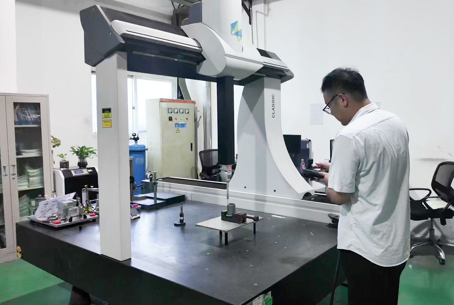
Inspection Methods and Measurement Equipment
When tolerances are measured in hundredths of a millimeter, you need measurement tools that match that precision. The gold standard for verifying cnc machine parts? Coordinate Measuring Machines—commonly known as CMMs.
A CMM provides accurate, repeatable measurement of a component's dimensions, surfaces, and geometric features. According to Metaltech Precision, CMMs are relied on to verify tight tolerances, confirm complex geometries, and validate machined features that cannot be checked reliably with manual tools.
How does a CMM work? The machine uses a probing system that moves through three axes, capturing data points on the part's surface. These points are compared against the CAD model to identify any deviations from nominal dimensions.
Types of CMM Probing
- Touch-trigger probing: Captures individual points when the probe contacts the surface—fast for discrete measurements
- Scanning probes: Maintain continuous contact with the surface, collecting thousands of data points along a feature. This provides better visibility of form, roundness, and surface condition
- Optical measurement: Non-contact systems using lasers or structured light for delicate parts or soft materials
The difference matters. As Metaltech notes, scanning collects continuous data as the probe tracks the feature, offering better visibility of form, roundness, and surface condition—useful for identifying issues such as ovality that single-point measurements might miss.
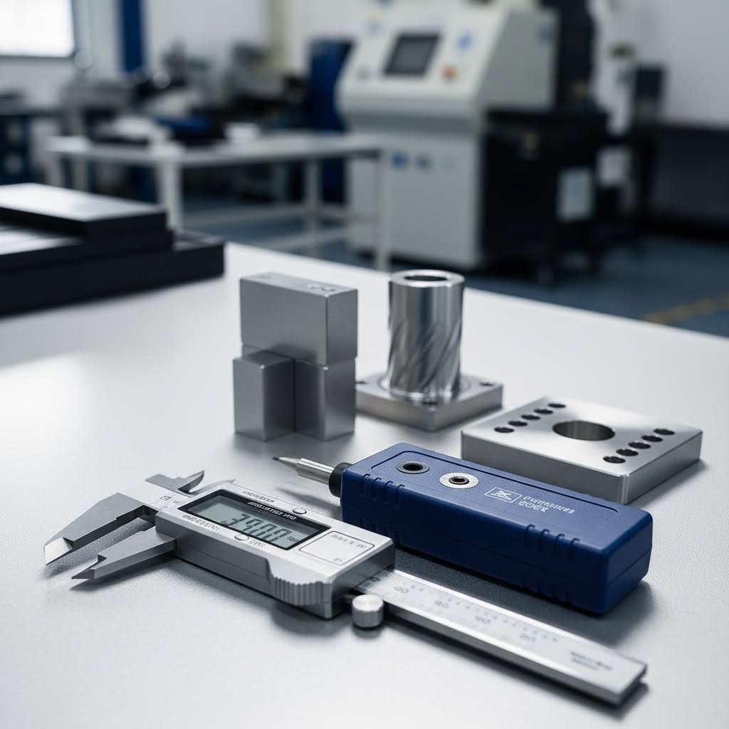
Beyond CMMs, quality facilities employ additional measurement tools:
- Surface roughness testers: Measure Ra values to verify surface finish specifications
- Optical comparators: Project magnified part profiles for visual comparison against drawings
- Hardness testers: Verify material properties using Rockwell, Brinell, or Vickers methods
- Height gauges and micrometers: Quick checks for critical dimensions during primary machining operations
Common Machining Defects and Prevention Strategies
Even the best CNC machines can produce defective parts when parameters aren't optimized or designs push manufacturing limits. Understanding what can go wrong—and why—helps you prevent issues through smarter design choices and better supplier communication.
According to 3ERP, CNC machining defects range from surface irregularities to tool breakage, each affecting the final quality of the machined part.
- Burr formation: Small raised edges at part boundaries caused by material deformation during cutting. Prevention includes optimizing cutting parameters, using sharp tools, and designing parts with chamfered edges where possible.
- Tool marks: Visible lines or ridges on machined surfaces from tool-workpiece interaction. Prevention involves proper feed rate selection, finishing passes, and maintaining tool sharpness.
- Dimensional drift: Parts gradually moving out of tolerance during production runs. Causes include thermal expansion, tool wear, and machine vibration. Prevention requires temperature-controlled environments, regular tool monitoring, and in-process inspection.
- Surface finish irregularities: Rough textures or uneven surfaces deviating from specifications. Causes include incorrect feed rates, tool wear, or inadequate coolant. Prevention involves parameter optimization and proper coolant application.
- Chatter marks: Regular wavy patterns indicating vibration during cutting. Prevention includes rigid workholding, optimized spindle speeds, and appropriate depth of cut.
- Thermal damage: Discoloration or material property changes from excessive heat. Prevention requires adequate cooling, appropriate cutting speeds, and sharp tools—especially important when working with materials like machinable nylon that soften at elevated temperatures.
The key insight? Most defects trace back to either parameter selection, tool condition, or design decisions. Proper Design for Manufacturing reduces defect risk significantly before machining even begins.
Quality Documentation and Traceability Requirements
For regulated industries, inspection results mean nothing without proper documentation. Quality records provide the evidence that parts meet specifications—and enable traceability if issues arise later.
First Article Inspection (FAI)
First Article Inspection serves as a preliminary check ensuring the initial produced part aligns with design and quality requirements. According to 3ERP, manufacturers examine the first article produced in a production run to confirm it meets specified dimensional and functional criteria.
FAI reports typically include:
- Complete dimensional verification of all drawing callouts
- Material certifications confirming composition
- Surface finish measurements
- Visual inspection results
- Any special process certifications (heat treatment, plating)
Statistical Process Control (SPC)
For production quantities, SPC provides ongoing process monitoring rather than 100% inspection. Control charts track critical dimensions over time, identifying trends before they result in defective parts. This approach enables operators to detect changes in the manufacturing process before they lead to scrap—reducing waste and maintaining consistency.
Traceability Requirements
Complete traceability links every finished part back to its raw material source, machining parameters, operator, and inspection results. This documentation enables:
- Root cause analysis when issues occur
- Targeted recalls affecting only specific production lots
- Compliance with aerospace, medical, and automotive standards
- Continuous improvement through data analysis
When evaluating machining parts manufacturers, ask about their documentation capabilities. Can they provide detailed dimensional reports? Do they maintain calibration records for inspection equipment? How do they handle nonconforming material? These questions reveal whether a supplier can meet your quality requirements—not just in machining capability, but in the documentation that proves it.
Quality control represents the verification step—but selecting the right manufacturing partner in the first place determines whether you'll face quality challenges at all. Let's explore how to evaluate and choose the right CNC machining partner for your needs.
Selecting the Right CNC Machining Partner
You've mastered the fundamentals of CNC machining of parts—from processes and materials to tolerances and quality control. Now comes the decision that ties everything together: choosing the manufacturing partner who will transform your designs into reality. This choice affects quality, cost, lead time, and ultimately, your project's success.
Whether you're searching for cnc machine shops near me or evaluating global suppliers, the evaluation criteria remain consistent. Let's explore what separates exceptional partners from adequate ones—and how to build relationships that deliver results for years to come.
Evaluating CNC Machining Service Providers
Not all machine shops are created equal. According to 3ERP, choosing a CNC machining service involves more than just comparing prices—it requires a thorough evaluation of experience, equipment, certifications, lead times, and communication effectiveness.
When researching a machinist near me or distant suppliers, systematically assess these critical factors:
Equipment and Technical Capabilities
A CNC machining service is only as effective as the tools at its disposal. Different types of CNC machines cater to different tasks—3-axis mills for simpler geometries, 5-axis configurations for complex surfaces, and Swiss lathes for precision small parts. Ask potential partners about:
- Range of machinery (3-axis, 4-axis, 5-axis milling; turning centers; EDM)
- Maximum workpiece dimensions they can accommodate
- Achievable tolerances with their equipment
- Secondary capabilities like surface grinding, heat treatment, or finishing
Certifications and Quality Systems
Certifications serve as independent verification of quality management capabilities. Look for ISO 9001 as a baseline—it demonstrates commitment to consistent quality. Industry-specific certifications like IATF 16949 for automotive, AS9100 for aerospace, or ISO 13485 for medical devices indicate specialized expertise and documented process controls.
Experience and Track Record
Experience equates to expertise. An experienced service provider would be familiar with handling diverse machining needs, reducing the chances of errors. Don't just look at years of operation—examine the types of projects they've completed and the industries they've served. Request case studies or references from similar applications.
Lead Time and Flexibility
Time is money in manufacturing. Understanding typical lead times is crucial—some suppliers offer delivery from just a few business days, while others may require weeks. Ask about policies on expedited orders should you require quicker turnarounds, and verify their track record for on-time delivery.
Communication and Responsiveness
Communication is the backbone of any successful partnership. An effective communication process means the service provider can promptly address your queries, update you on progress, and quickly rectify any issues that may arise. Look for transparent communication channels and designated points of contact.
From Prototype to Production
The journey from initial concept to full-scale manufacturing rarely happens in a single leap. According to UPTIVE Advanced Manufacturing, prototyping is the critical testing phase where ideas are shaped, refined, and validated for manufacturing and market success.
Why Prototyping Matters
Rapid prototyping capabilities can significantly reduce your product development cycle. By creating a prototype quickly, you can evaluate the design, function, and performance of your parts before committing to full-scale production. This approach:
- Identifies design issues early—when changes are least expensive
- Validates material choices under real-world conditions
- Confirms tolerances are achievable and appropriate
- Provides physical samples for stakeholder review and testing
Low-Volume Production Bridge
Manufacturing at low volume bridges the gap between prototyping and full-scale production. It helps catch design, manufacturing, or quality issues while validating processes and assessing suppliers in terms of quality, responsiveness, and lead times. Use this phase to:
- Finalize your Bill of Materials (BOM)
- Define quality standards and inspection protocols
- Document any changes for future reference
- Build confidence before committing to larger orders
Scaling to Production
When comparing potential partners, consider their service offerings, reliability, scalability, and expertise in handling your product type. A partner with both prototyping capabilities and production scalability can accelerate your supply chain by managing the entire process—eliminating handoffs between different suppliers.
Certified manufacturers maintaining IATF 16949 certification and implementing Statistical Process Control (SPC) can deliver high-tolerance components consistently across production volumes. For automotive and industrial applications requiring fast turnaround—sometimes with lead times as short as one working day—partners like Shaoyi Metal Technology offer the combination of rapid prototyping, quality certification, and production scalability that keeps supply chains moving.
Building Effective Manufacturing Partnerships
The best supplier relationships extend beyond transactional orders. Building an effective manufacturing partnership requires investment from both sides—but the returns include better quality, faster response, and preferential treatment when capacity is tight.
Requesting Quotes Effectively
When seeking a cnc quote online, the quality of information you provide directly affects quote accuracy and turnaround time. According to Mectalent, a carefully prepared request for quotation speeds up the process—the more detailed the RFQ, the faster you'll receive accurate pricing.
Include these elements when requesting online machining quotes:
- 3D CAD files: STEP format preferred, with PDF drawings as the master reference
- Material specifications: Grade, condition, and whether you're supplying material
- Quantity requirements: Current order and anticipated annual volumes
- Tolerance callouts: Especially for critical dimensions tighter than standard
- Surface finish requirements: Ra values and any special finish needs
- Industry requirements: Certifications, documentation, or traceability needs
- Delivery timeline: Required date and any flexibility
Questions to Ask Potential Suppliers
Before committing to a partnership—whether with local machine shops or distant suppliers—get clear answers to these essential questions:
- What certifications do you hold, and what's the scope of each?
- What are your standard lead times, and can you accommodate expedited orders?
- How do you handle design feedback or DFM recommendations?
- What inspection equipment do you use, and what documentation can you provide?
- How do you manage quality for production runs versus prototypes?
- What's your process for handling nonconforming parts?
- Can you scale from prototype to production without changing suppliers?
- Who will be my primary point of contact for technical questions?
Long-Term Partnership Benefits
Suppliers who understand your products, quality requirements, and business rhythms become extensions of your engineering team. They can:
- Proactively identify design improvements that reduce cost or improve quality
- Prioritize your orders when capacity is constrained
- Maintain tooling and fixtures for repeat orders
- Provide faster quotes based on familiarity with your requirements
- Invest in capabilities that support your future needs
Whether you find machining shops near me or partner with specialized facilities across the globe, the principles remain the same: evaluate capabilities thoroughly, start with prototypes to validate the relationship, communicate clearly about requirements, and invest in partnerships that grow stronger over time.
The right CNC machining partner doesn't just make parts—they help bring your designs to life with the precision, quality, and reliability your applications demand.
Frequently Asked Questions About CNC Machining of Parts
1. How much does it cost to get a part CNC machined?
CNC machining costs vary based on complexity, material, and tolerances. Hourly rates typically range from $50 to $150, with setup fees starting at $50 and exceeding $1,000 for complex projects. Per-part costs remain relatively constant regardless of quantity, making CNC ideal for prototypes and low-volume production of 1-500 pieces. For high-tolerance automotive components with fast turnaround needs, certified partners like Shaoyi Metal Technology offer competitive pricing with lead times as short as one working day.
2. What materials cannot be CNC machined?
CNC machining struggles with rubber and flexible polymers like silicone, carbon fiber composites that cause rapid tool wear, ceramics and glass that are too brittle, super soft metals that deform during cutting, and foam materials lacking structural integrity. However, CNC handles virtually all engineering metals including aluminum, steel, titanium, brass, and bronze, plus rigid plastics like Delrin, nylon, polycarbonate, and acrylic with excellent results.
3. What is the difference between CNC milling and CNC turning?
CNC milling uses rotating cutting tools against stationary workpieces to create flat surfaces, pockets, slots, and complex 3D contours. CNC turning rotates the workpiece against stationary tools, ideal for cylindrical components like shafts, pins, and bushings. Milling offers greater geometric flexibility with 3-axis through 5-axis configurations, while turning delivers faster cycle times and excellent surface finishes for round parts.
4. What tolerances can CNC machining achieve?
Standard CNC machining achieves tolerances of ±0.1 to ±0.2 mm under ISO 2768-m guidelines. Precision applications reach ±0.01 to ±0.05 mm, while high-precision work using ISO 286 IT6-IT7 grades achieves ±0.013 to ±0.025 mm for critical features. Tolerances below ±0.025 mm require advanced machinery, climate-controlled environments, and rigorous quality control—capabilities that IATF 16949 certified facilities with Statistical Process Control can deliver consistently.
5. When should I choose CNC machining over 3D printing or injection molding?
Choose CNC machining when you need tight tolerances (±0.05 mm vs 3D printing's ±0.2 mm), production-representative material properties, superior surface finishes, or quantities between 1-500 parts. Injection molding becomes cost-effective at 500-5,000+ units after tooling investment. 3D printing excels for complex internal geometries and rapid design iteration. Many projects benefit from hybrid approaches—CNC prototypes validating designs before transitioning to molding for volume production.