 Small batches, high standards. Our rapid prototyping service makes validation faster and easier —

Sheet Metal Shearing Decoded: From Machine Types To Flawless Cuts
What Sheet Metal Shearing Actually Means for Fabricators
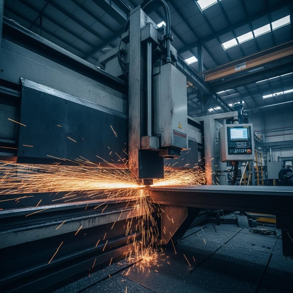
Ever wondered how fabricators slice through metal sheets with such precision—without melting, burning, or creating waste chips? The answer lies in a process that's been fundamental to metalworking for decades.
Sheet metal shearing is a cold mechanical cutting process where material is positioned between two sharp blades, and a powerful downward force causes the metal to fracture cleanly along a defined cut line—without chip formation, melting, or heat distortion.
Think of it like using scissors on paper, except the forces involved are exponentially greater. The shearing meaning in metal fabrication centers on this simple yet effective principle: apply enough pressure between opposing blades, and the material separates cleanly along the intended path.
The Mechanics Behind Clean Metal Cuts
So what is shearing from a physics standpoint? The process works through precise mechanical action. A lower blade (or die) remains stationary while an upper blade descends with tremendous force. The two blades are separated by only thousandths of an inch at the point of cut—typically 5-10% of the material thickness.
Here's what happens during shearing in sheet metal operations:
- Hold-down clamps secure the material before the upper blade makes contact
- The descending blade applies stress that exceeds the metal's ultimate shear strength
- The material fractures cleanly along the cut line
- No material is removed—unlike drilling or milling operations
What is a shear in practical terms? It's essentially any machine designed to execute this blade-against-blade cutting action, whether powered hydraulically, mechanically, or pneumatically.
How Shearing Differs from Other Cutting Methods
Understanding what sets this process apart helps you make smarter fabrication decisions. Unlike laser cutting that vaporizes material or plasma cutting that uses superheated ionized gas, shearing produces virtually no kerf—meaning shearing creates minimal material waste.
This distinction matters for three critical reasons:
- Material selection: Soft metals like aluminum, brass, and low-carbon steel respond exceptionally well since there's no heat-affected zone
- Cost control: Faster processing speeds and minimal waste translate directly to lower per-part costs in high-volume production
- Quality outcomes: Properly executed cuts produce clean edges without the thermal distortion common to heat-based methods
The ability to cut sheet metal without burning or forming chips makes this process ideal for preparatory work—transforming large sheets into workable blanks for subsequent operations. Whether you're running a small workshop or managing large-scale production, grasping these fundamentals positions you to optimize both quality and efficiency throughout your fabrication workflow.
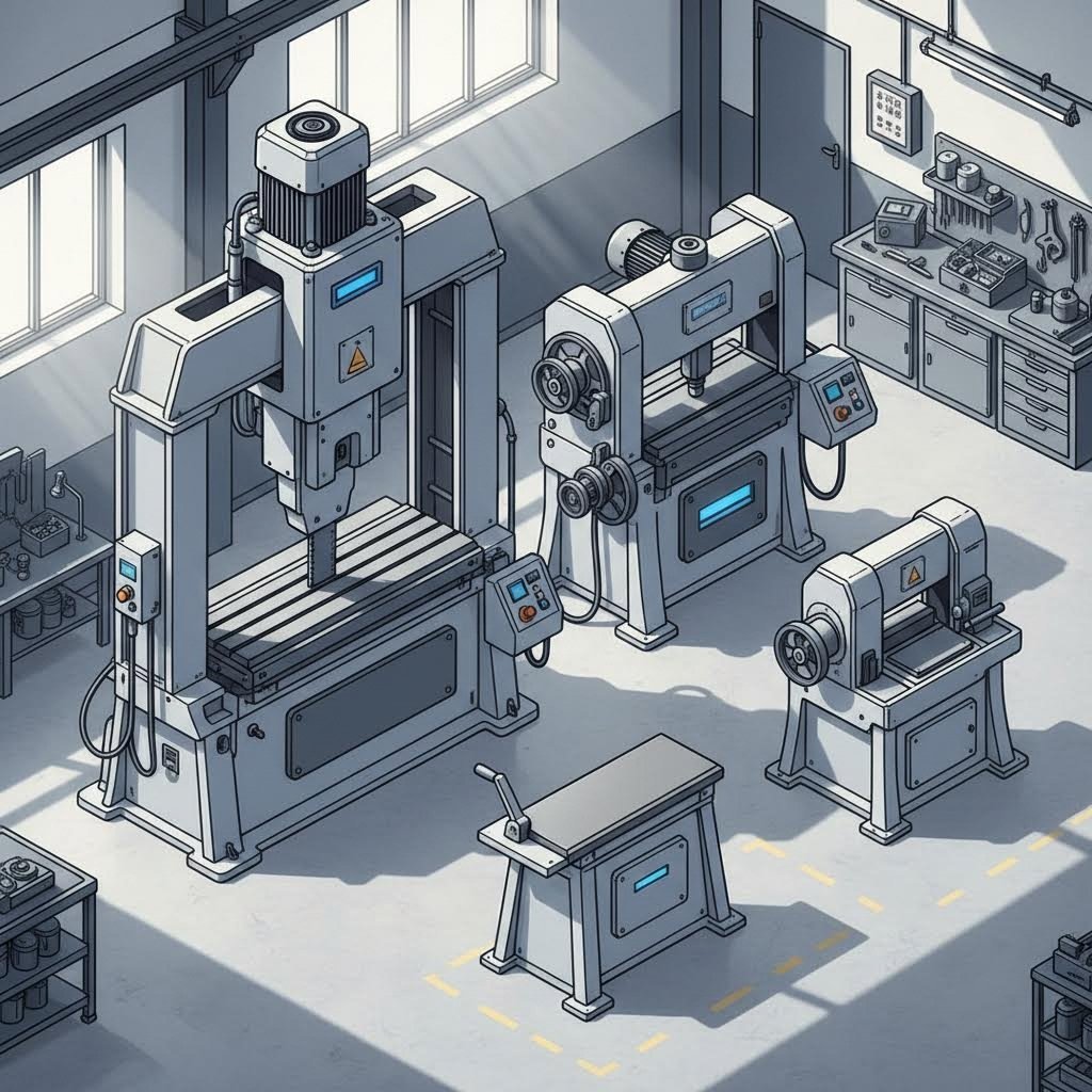
Types of Shearing Machines and Their Ideal Applications
Now that you understand the fundamental mechanics, the next question becomes: which machine actually fits your production needs? Selecting the right sheet metal shear isn't just about cutting capacity—it's about matching your equipment to your specific workflow, materials, and budget constraints.
From compact bench units to massive hydraulic systems capable of slicing through 25mm plate, the range of available equipment can feel overwhelming. Let's break down each category so you can make an informed decision.
Guillotine Shears for High-Volume Production
Guillotine shears work similarly to a paper trimmer—a fixed upper blade descends onto a stationary lower blade, making precise straight cuts. These machines dominate high-production environments for good reason.
There are two primary configurations you'll encounter:
- Hydraulic guillotine shears: Use fluid pressure to generate cutting force, offering smooth operation and excellent control over blade movement. Ideal for thicker materials (typically 6mm and above) where consistent pressure matters more than raw speed.
- Mechanical guillotine shears: Rely on flywheel energy released through clutch mechanisms, delivering rapid cutting cycles that can exceed 60 strokes per minute. Perfect for thin-gauge materials under 4mm where production volume is the priority.
According to industry specialists, mechanical shears function like sprinters—built for explosive speed but limited flexibility—while hydraulic versions resemble weightlifters, offering immense power with precise control.
Bench Shears and Their Workshop Applications
What about smaller operations? A small sheet metal shear mounted on a workbench provides surprising capability without consuming valuable floor space.
Bench shears typically handle light to medium-gauge materials and come in several varieties:
- Manual lever shears: Operated by hand for occasional cutting tasks—no power required
- Foot-operated shears: Free up both hands for material positioning while delivering consistent cutting force
- Electric bench shears: Combine compact size with motorized power for increased productivity
These machines excel at cutting rough shapes and making quick adjustments during fabrication. Ground cutting blades on quality units deliver clean, quick cuts without the investment of larger power shearing equipment.
Power Shearing Systems Explained
Power shearing encompasses the broader category of motorized shear cutting machines designed for industrial throughput. The three main power sources each offer distinct advantages:
Mechanical systems store rotational energy in heavy flywheels. When the clutch engages, this stored energy releases instantaneously through a crank mechanism. The result? Cutting speeds that hydraulic systems simply cannot match for thin materials.
Hydraulic systems use pressurized fluid to move the blade with precise, adjustable force. This makes them incredibly versatile—operators can fine-tune pressure settings for different material thicknesses without mechanical modifications.
Pneumatic systems power smaller die shear operations and specialized applications where clean, oil-free operation matters. They're common in electronics manufacturing and cleanroom environments.
Interestingly, modern sheer cutter technology has blurred traditional boundaries. Servo-hydraulic hybrids now combine the speed responsiveness of mechanical systems with hydraulic precision, representing the cutting edge of power shearing innovation.
| Machine Type | Typical Thickness Capacity | Speed (Strokes/Min) | Best Applications | Relative Cost |
|---|---|---|---|---|
| Manual Bench Shear | Up to 1.5mm mild steel | Manual operation | Light fabrication, prototyping, hobbyist work | $ |
| Electric Bench Shear | Up to 3mm mild steel | 20-30 | Small workshops, maintenance shops, HVAC ductwork | $$ |
| Mechanical Guillotine | Up to 6mm mild steel | 40-60+ | High-volume thin sheet production, appliance manufacturing | $$$ |
| Hydraulic Swing Beam | Up to 16mm mild steel | 10-25 | General fabrication, mixed thickness work, flexible production | $$$ |
| Hydraulic Guillotine | Up to 25mm+ mild steel | 6-15 | Heavy plate cutting, structural steel, high-strength materials | $$$$ |
How does machine selection impact your bottom line? Consider three factors:
- Cut quality: Hydraulic machines with adjustable blade gaps produce consistently cleaner edges across varying thicknesses, while mechanical units may require more frequent clearance adjustments
- Production speed: For thin materials under 4mm, mechanical shears can double or triple output compared to hydraulic alternatives—a significant advantage in high-volume scenarios
- Operational costs: Mechanical systems generally require more maintenance on clutches and friction components, while hydraulic units need regular fluid changes and seal inspections
The key takeaway? Match your machine to your most common cutting tasks. A shop processing primarily 0.5-2mm galvanized sheets benefits enormously from mechanical speed, while operations regularly handling 10mm+ plate should invest in hydraulic capability. Getting this decision right directly affects your competitiveness—but equally important are the technical parameters that determine whether your cuts meet specification.
Critical Parameters That Determine Shearing Quality
You've selected the right machine—but here's where many operators stumble. Even the most expensive hydraulic shear produces disappointing results when critical settings are misconfigured. Understanding shearing theory at the parameter level separates professionals from amateurs and directly determines whether your sheared material meets specification or ends up as scrap.
What is a shear cut that qualifies as truly acceptable? It comes down to mastering three interdependent variables: blade clearance, rake angle, and hold-down pressure. Get these right, and you'll achieve clean edges with minimal secondary finishing. Get them wrong, and you'll fight constant battles with burrs, edge deformation, and dimensional inconsistencies.
Blade Clearance Settings That Prevent Defects
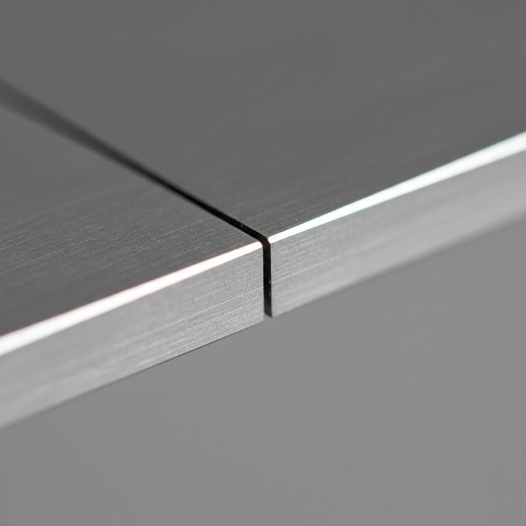
Blade clearance—the gap between upper and lower blades—is arguably the single most critical parameter in shear cutting operations. This seemingly small measurement, typically expressed as a percentage of material thickness, directly controls edge quality and burr formation.
The optimal range falls between 5-10% of material thickness for most metals. But here's what many guides fail to mention: this percentage varies significantly based on what you're cutting.
Consider these material-specific guidelines:
- Mild steel: 5-10% clearance—a 4mm sheet requires approximately 0.28mm gap (using 7% as the midpoint)
- Stainless steel: 8-12% clearance—harder material demands a wider gap to prevent blade damage
- Aluminum: 4-6% clearance—softer metals need tighter settings to avoid edge rollover
What happens when clearance settings miss the mark?
- Too tight: Excessive friction, accelerated blade wear, potential chipping, and increased cutting force requirements
- Too wide: Burr formation on the exit side, edge rollover, material deformation, and rough cut surfaces
Sounds complex? Think of it this way—imagine cutting fabric with scissors that don't quite meet. The material bunches, tears unevenly, and leaves ragged edges. Metal behaves similarly when blade gaps exceed optimal ranges.
Understanding Rake Angle Effects on Cut Quality
Rake angle (also called shear angle) describes how the upper blade tilts relative to the lower blade. This angle determines how progressively the blade contacts your material—and it has profound effects on both cutting force and edge appearance.
According to hydraulic shear specialists, a steeper rake angle reduces required cutting force but may cause more material movement during the cut. Here's how different angles perform:
| Rake Angle Type | Effect on Force | Edge Quality Impact | Best Application |
|---|---|---|---|
| Positive (steeper) | Lower cutting force required | Cleaner, sharper edges | Thin sheets, soft metals |
| Negative (flatter) | Higher cutting force required | May leave rougher finish | Thick plates, maximum blade strength |
| Neutral (moderate) | Balanced force requirements | Good general-purpose finish | Mixed production environments |
For thicker materials, larger rake angles distribute cutting force more gradually—reducing stress on both the machine and the workpiece. Thinner sheets often benefit from smaller angles that maintain dimensional accuracy without excessive material displacement.
Hold-Down Pressure and Material Control
You might have perfect clearance and ideal rake angles, yet still produce unacceptable cuts. Why? Inadequate hold-down pressure allows material to shift during shearing, causing dimensional inaccuracies and potentially dangerous situations.
Hold-down clamps serve two essential functions:
- Securing position: Preventing lateral movement that causes crooked cuts and dimensional errors
- Controlling deformation: Limiting material lift and twist during blade penetration
Finding the right pressure requires balancing competing demands. Too much pressure marks softer materials like aluminum or thin stainless—leaving visible clamp impressions that may require additional finishing. Insufficient pressure allows the sheet to creep during cutting, producing inaccurate dimensions and inconsistent edges.
Here are the key parameters operators must control for quality shear cutting results:
- Blade clearance percentage matched to material type and thickness
- Rake angle appropriate for sheet gauge and production requirements
- Hold-down pressure calibrated to prevent movement without surface marking
- Blade sharpness maintained through regular inspection and timely replacement
- Blade alignment verified to ensure parallel contact across the entire cut length
- Backstop positioning for accurate, repeatable dimensions
When adjusting parameters for different materials, always test settings on scrap pieces first. What works perfectly for 2mm mild steel won't translate directly to 2mm stainless—the harder material requires both wider clearance and potentially different hold-down settings. Document your successful configurations so you can reproduce quality results consistently across production runs.
With these technical fundamentals established, you're equipped to tackle the next challenge: understanding exactly which materials respond well to shearing—and what thickness limitations apply to each.
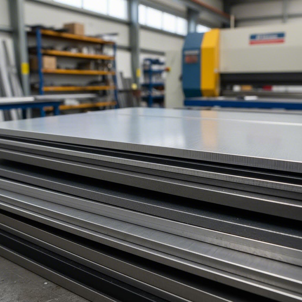
Material Suitability and Thickness Guidelines for Shearing
Now that you understand the critical parameters, here's the practical question: can your shear actually handle the material sitting on your shop floor? Not all metals respond equally to this cutting process—and pushing beyond recommended limits risks everything from poor edge quality to serious equipment damage.
Material properties directly dictate shearing success. Hardness determines cutting force requirements. Ductility affects how cleanly the metal fractures. Thickness establishes whether your machine has adequate capacity. Understanding these relationships helps you shear sheet metal effectively while protecting your investment.
Mild Steel and Carbon Steel Shearing Guidelines
Steel shearing represents the bread-and-butter work for most fabrication shops. Mild steel (also called low-carbon steel) offers the most forgiving cutting characteristics, which is why machine manufacturers typically rate capacity using this material as the baseline.
When you need to shear steel with different carbon content, tensile strength becomes your critical calculation factor. According to industry guidelines, the formula for determining maximum thickness is:
Maximum Thickness = Rated Capacity × (Rated Tensile Strength ÷ Material Tensile Strength)
Here's what this means practically:
- Low-carbon steel (A36): Tensile strength around 400-550 MPa—most machines handle this at full rated capacity
- Medium-carbon steel: Higher tensile strength (550-750 MPa) reduces effective cutting thickness by 20-30%
- High-carbon steel: Significantly harder material may require reducing rated capacity by 40% or more
Temperature matters too. Cold-rolled steel cuts more cleanly than hot-rolled material with its characteristic mill scale. That oxide layer acts like sandpaper against your blades, accelerating wear and potentially compromising edge quality.
Aluminum and Soft Metal Considerations
Aluminium shearing presents unique opportunities and challenges. The good news? Aluminum's lower tensile strength (typically 70-310 MPa depending on alloy) means your machine can handle significantly thicker sheets than its mild steel rating suggests.
Using the calculation from earlier: if your shear rates at 6mm for mild steel (450 MPa), it can theoretically cut aluminum (250 MPa) up to approximately 10.8mm thick. That's nearly double the capacity—a substantial advantage for shops processing aluminum regularly.
However, aluminum's softness creates its own complications:
- Edge galling: Material can smear rather than fracture cleanly, leaving rough surfaces
- Blade adhesion: Soft aluminum may stick to blade edges, requiring more frequent cleaning
- Tighter clearances needed: Use 4-6% clearance versus 5-10% for steel to prevent rollover
Other soft metals like brass, copper, and bronze follow similar principles. Their ductility allows thicker cuts but demands careful parameter adjustment to maintain clean edges.
Stainless Steel Challenges and Solutions
Shearing stainless steel tests both operator skill and equipment capability. With tensile strengths ranging from 515-860 MPa (significantly higher than mild steel), stainless steel shearing requires substantial adjustments to standard practices.
The math tells the story clearly. That same 6mm-rated machine handling 450 MPa mild steel can only safely cut approximately 3.1mm of 304 stainless steel (tensile strength around 860 MPa). Attempting to exceed this limit risks blade damage, poor cut quality, and potentially dangerous equipment strain.
Successful stainless steel shearing requires these adjustments:
- Increase blade clearance: Use 8-12% of material thickness rather than the 5-10% standard for mild steel
- Reduce cutting speed: Slower blade travel prevents work hardening at the cut edge
- Ensure blade sharpness: Dull blades dramatically worsen edge quality on hardened materials
- Apply proper lubrication: Reduces friction and heat buildup during cutting
Different stainless grades behave differently. Austenitic grades (304, 316) work-harden during cutting, while ferritic grades (430) cut more predictably. Knowing your specific alloy helps dial in optimal parameters.
| Material Type | Typical Tensile Strength (MPa) | Max Thickness (% of Mild Steel Rating) | Recommended Blade Clearance | Special Considerations |
|---|---|---|---|---|
| Mild Steel (A36) | 400-550 | 100% | 5-10% | Baseline material; remove mill scale before cutting |
| Aluminum (6061) | 240-310 | 150-180% | 4-6% | Use tighter clearance; clean blades frequently to prevent galling |
| Copper | 210-360 | 125-200% | 4-7% | Soft and ductile; may require slower cutting speeds |
| Brass | 340-470 | 100-130% | 5-8% | Cuts cleanly; moderate blade wear |
| 304 Stainless | 515-620 | 70-85% | 8-12% | Work hardens; use sharp blades and proper lubrication |
| 316 Stainless | 515-690 | 65-85% | 8-12% | Higher corrosion resistance; similar cutting behavior to 304 |
| High-Carbon Steel | 690-860 | 50-65% | 10-14% | Very hard; accelerates blade wear significantly |
Beyond these common materials, always verify material condition before cutting. Industry experts note that materials with impurities, scale, or uneven hardness decrease effective shearing capability. Always use clean, properly prepared sheets for best results.
Thickness limitations also interact with cut length. As material thickness approaches maximum rated capacity, you may need to reduce shearing width proportionally to avoid machine overload. Manufacturers typically provide charts showing these combinations—consult them before pushing capacity boundaries.
Understanding material suitability prevents costly mistakes, but what happens when cuts don't meet expectations despite proper material selection? The next section addresses exactly that—diagnosing and solving the most common shearing defects.
Troubleshooting Common Shearing Defects and Solutions
You've configured your parameters correctly, selected appropriate materials, and started production—yet something's off. The edges look rough, parts are twisting, or dimensions simply don't match specifications. Sound familiar? Even experienced operators encounter these frustrations when shearing metal under production conditions.
The difference between a seasoned professional and a struggling operator often comes down to diagnostic ability. Knowing how to identify defects, trace their root causes, and implement corrective actions separates efficient operations from those plagued by scrap and rework. Let's walk through the most common problems you'll encounter when working with sheared metal—and exactly how to fix them.
Diagnosing and Eliminating Burr Formation
Burrs—those raised, sharp projections along cut edges—represent the most frequently reported defect in cutting shear operations. Beyond being aesthetically unacceptable, burrs create safety hazards for handlers, interfere with assembly operations, and often require costly secondary deburring processes.
What causes burrs during the shearing process? According to industry troubleshooting guides, burr formation typically stems from several interconnected factors:
-
Problem: Dull or worn blades
Solution: Inspect blade edges for rounding or damage. Worn blades tear rather than shear the material cleanly. Replace or resharpen blades when edge quality deteriorates—studies show daily cleaning extends blade life 25-35%. -
Problem: Excessive blade clearance
Solution: Reduce the gap between upper and lower blades. When clearance exceeds 10-12% of material thickness, the metal bends into the gap rather than fracturing cleanly. Recalibrate using manufacturer specifications for your specific material. -
Problem: Blade misalignment
Solution: Verify parallel alignment across the entire blade length. Even slight misalignment causes uneven pressure distribution, resulting in burrs on one side of the cut. Use precision measurement tools weekly as part of routine maintenance. -
Problem: Wrong blade material for the application
Solution: Match blade composition to workpiece hardness. Cutting stainless steel with blades designed for mild steel accelerates wear and increases burr formation. Consider carbide-tipped blades for harder materials.
Here's a practical tip: run your finger carefully along the cut edge (with proper safety gloves). Burrs consistently appearing on the bottom side indicate clearance that's too wide. Burrs on the top side suggest the opposite problem or blade dullness. This quick diagnostic helps narrow down corrective actions before deeper investigation.
Correcting Edge Deformation and Twisting
Material distortion manifests as warping, bending, or twisting of shearing material during or after the cut. These defects compromise dimensional accuracy and create significant problems in downstream assembly or fabrication steps.
When sheared metal refuses to lie flat or exhibits edge rollover, investigate these common causes:
-
Problem: Uneven cutting force distribution
Solution: Ensure the hold-down system applies uniform pressure across the entire sheet width. Calibrate shearing machines with even pressure distribution systems, and verify the support table is level and debris-free. -
Problem: Residual stress in the material
Solution: Material arriving from previous manufacturing processes may contain internal stresses that release unpredictably during shearing. Consider annealing sheets before cutting for critical applications, or source stress-relieved material. -
Problem: Inadequate hold-down pressure
Solution: Increase clamping force to prevent the sheet from lifting or shifting during blade penetration. However, balance this against potential surface marking on softer materials—test on scrap pieces first. -
Problem: Excessive rake angle for material thickness
Solution: Steeper rake angles reduce cutting force but can cause more material displacement. For thicker sheets prone to twisting, reduce the rake angle even though this increases force requirements. -
Problem: Cutting force exceeds material stability
Solution: For thicker materials prone to distortion, employ multiple smaller shears rather than a single large cut. This distributes stress more evenly and reduces cumulative deformation.
Edge rollover—where the cut edge curves rather than remaining square—often indicates blade clearance that's too tight for softer materials like aluminum. Slightly increasing clearance typically resolves this issue while maintaining acceptable edge quality.
Preventing Bowing in Long Cuts
Long cuts present unique challenges. As the blade progresses across extended sheet lengths, accumulated stress can cause the material to bow—curving upward or downward from the cut line. This defect becomes increasingly pronounced as cut length increases.
Addressing bowing requires attention to both machine setup and cutting technique:
-
Problem: Inadequate material support during cutting
Solution: Ensure proper support tables extend sufficiently beyond the machine. Sagging sheets create uneven stress distribution that manifests as bowing. Consider additional roller supports for extra-long pieces. -
Problem: Inconsistent blade engagement across cut length
Solution: Check blade parallelism and machine frame rigidity. Worn guides or loose mounting hardware allows blades to shift during extended cuts, producing inconsistent results. -
Problem: Material grain direction affecting cut behavior
Solution: Cutting perpendicular to grain direction often produces cleaner, flatter results than cutting parallel to grain. When possible, orient sheets to take advantage of grain characteristics.
Post-shearing techniques can address minor bowing that occurs despite proper setup. Flattening or leveling processes apply controlled pressure to return sheared pieces to intended dimensions. However, prevention through proper technique remains more cost-effective than correction.
Achieving Consistent Dimensional Accuracy
Beyond visible defects like burrs and distortion, dimensional inconsistency undermines production quality just as severely. When cut parts vary in length or width from piece to piece, assembly becomes problematic and scrap rates climb.
-
Problem: Backstop positioning errors
Solution: Verify backstop calibration using precision measuring tools before each production run. Mechanical wear, debris accumulation, or temperature changes can cause drift in positioning accuracy. -
Problem: Material slippage during cutting
Solution: Increase hold-down pressure and verify clamp condition. Worn or contaminated clamp surfaces lose grip, allowing sheets to creep during blade engagement. Clean and inspect clamping components regularly. -
Problem: Blade deflection under load
Solution: When cutting near maximum capacity, blades may deflect slightly, affecting dimensional accuracy. Either reduce sheet width when working thick materials or upgrade to a higher-capacity machine for consistent results. -
Problem: Temperature-induced dimensional changes
Solution: Metal expands when warm and contracts when cool. For precision work, allow materials to stabilize at ambient shop temperature before shearing. Avoid cutting immediately after materials arrive from outdoor storage.
What tolerances can you realistically achieve? Well-maintained shearing equipment typically holds dimensional accuracy within ±0.25mm for standard operations. High-precision machines with properly calibrated backstops can achieve ±0.1mm or better. However, these capabilities assume sharp blades, correct clearances, and properly secured materials.
Quick Reference: Defect Diagnosis and Solutions
| Defect | Visual Indicators | Primary Causes | Corrective Actions |
|---|---|---|---|
| Excessive Burrs | Sharp projections along cut edge | Dull blades, excessive clearance, misalignment | Sharpen/replace blades, reduce clearance, verify alignment |
| Edge Rollover | Curved or rounded edge profile | Clearance too tight for material, dull blades | Increase clearance slightly, replace worn blades |
| Material Twisting | Sheet rotates or warps after cut | Uneven hold-down, residual stress, excessive rake | Adjust clamp pressure, reduce rake angle, anneal material |
| Bowing | Curved deviation along cut length | Poor support, blade inconsistency, grain direction | Improve support tables, check blade parallelism, reorient material |
| Inconsistent Dimensions | Part-to-part size variation | Backstop drift, material slippage, blade deflection | Recalibrate stops, increase clamping, reduce sheet width |
| Rough Cut Surface | Jagged or uneven cut face | Blade wear, incorrect speed, material contamination | Replace blades, adjust cutting speed, clean material surface |
According to hot rolling mill specialists, maintaining consistent cut lengths and quality directly affects production throughput and material yield. Early detection of defect patterns helps operators implement corrections before significant material waste occurs.
Remember that multiple defects often share common root causes. If you're experiencing both burrs and dimensional inconsistency simultaneously, worn blades likely contribute to both problems. Addressing the fundamental issue—blade condition—resolves multiple symptoms at once.
Mastering troubleshooting transforms shearing from a constant battle into a predictable process. But how does this cutting method compare to alternatives when defect-free results prove difficult to achieve? Understanding the trade-offs between shearing and other cutting technologies helps you make smarter process selection decisions.
Shearing Compared to Laser Plasma and Waterjet Cutting
So you've mastered shearing parameters and troubleshooting—but here's a question that keeps coming up: when should you actually choose sheet shearing over laser, plasma, or waterjet cutting? Each method has its champions, and the "best" choice depends entirely on your specific application, budget, and quality requirements.
Understanding these trade-offs prevents costly mistakes. You might invest in expensive laser equipment when simple shearing would deliver identical results at a fraction of the cost. Or you might struggle with shearing limitations when alternative technologies would solve your problems instantly. Let's break down each option so you can make informed decisions.
Shearing vs Laser Cutting Trade-offs
Laser cutting has become the darling of modern fabrication—and for good reason. Using a focused beam of light assisted by gas, lasers slice through metal with remarkable precision. But does precision always justify the investment?
According to industry comparisons, the initial investment for laser cutting machines significantly exceeds that of hydraulic shearing equipment. Laser systems require advanced technology and precision engineering, while shearing machines offer more accessible entry points for businesses with limited budgets.
Here's where each technology excels:
Advantages of Shearing
- Substantially lower equipment costs—often 50-70% less than comparable laser systems
- Faster processing speeds for straight cuts in production environments
- No heat-affected zone (HAZ) means zero thermal distortion
- Minimal material waste with virtually no kerf
- Simpler maintenance requirements and lower operational costs
- Excellent for high-volume blanking metal operations
Advantages of Laser Cutting
- Intricate designs and complex geometries impossible with shearing
- Tighter tolerances for precision components
- Versatility across metals, plastics, wood, and composites
- No physical contact with material—eliminating tool wear concerns
- Ideal for prototyping and low-volume custom work
The decision often comes down to geometry. Need straight cuts across sheet metal? Shearing wins on speed and cost. Require curved profiles, intricate cutouts, or complex shapes? Laser becomes the obvious choice despite higher investment.
Technical analysis shows that lasers usually cut metals under an inch thick efficiently, but edge quality can suffer with thicker materials. Additionally, laser cuts in plate thicknesses of 1/4" or more may develop wavy cross-sections and one or two degrees of taper—issues that never occur with properly configured shearing operations.
When Plasma or Waterjet Makes More Sense
What about plasma and waterjet cutting? These technologies occupy different niches in the fabrication landscape, each offering unique capabilities that shearing simply cannot match.
Plasma cutting uses super-heated ionized gas to burn through conductive metals. It's cheap, fast, and handles thicknesses up to several inches. For cutting rough shapes in metal, plasma pricing is hard to beat.
However, plasma has significant limitations compared to shearing:
- Confined exclusively to conductive metals
- Heat-affected zone causes warping and distortion
- Intricate geometries risk melting from excessive heat
- Produces noxious gases requiring ventilation
- Leaves slag requiring secondary cleaning
- Cannot cut stacked sheets like shearing can
Waterjet cutting represents a different philosophy entirely. Using high-pressure water mixed with abrasive particles, waterjets cut virtually any material without heat effects. According to waterjet specialists, this technology is "both the jack of all trades and the master of some."
Consider waterjet when you need:
- Heat-sensitive materials that cannot tolerate thermal cutting
- Extreme thickness capability—waterjets cut metals over a foot thick
- Reflective metals like copper and aluminum that challenge lasers
- Stacked sheet cutting without quality compromise
- Tight inside corners that lasers tend to blow out from heat concentration
But waterjet comes with trade-offs. Operating costs run higher than shearing due to abrasive consumption. Processing speeds generally lag behind both shearing and laser for thin materials. And the wet cutting environment requires different material handling considerations.
Blanking and Piercing as Shearing Alternatives
Within the mechanical cutting family, the blanking process deserves special attention. Like shearing, blanking metal uses punch and die sets to separate material through shearing action—but with a critical difference in purpose.
The blanking and piercing process creates shaped pieces rather than straight-line cuts:
- Steel blanking produces the finished part (the "blank") while discarding the surrounding material
- Piercing creates holes by discarding the interior material while keeping the surrounding sheet
- Sheet metal blanking excels in mass production where tooling costs amortize across thousands of parts
Nothing beats the per-part cost of blanking steel in high-volume production. Once tooling is created, each subsequent part costs pennies. However, custom tooling can be extremely expensive—making blanking impractical for short runs or prototype work.
Nibbling in sheet metal offers another alternative worth mentioning. This process uses a small punch to progressively cut complex shapes through overlapping strokes. While slower than single-stroke blanking, nibbling requires less expensive tooling and offers flexibility for varied geometries. It bridges the gap between simple shearing and complex laser cutting for certain applications.
Comprehensive Method Comparison
| Cutting Method | Speed | Precision | Thickness Range | Edge Quality | Setup Cost | Per-Part Cost |
|---|---|---|---|---|---|---|
| Shearing | Very Fast | ±0.1-0.25mm | Up to 25mm+ (mild steel) | Clean, minimal burr | Low-Medium | Very Low |
| Laser Cutting | Fast | ±0.05-0.1mm | Up to 25mm (varies by power) | Smooth, glossy finish | High | Medium |
| Plasma Cutting | Very Fast | ±0.5-1.5mm | Up to 150mm+ | Rough, requires cleanup | Medium | Low |
| Waterjet | Slow-Medium | ±0.1-0.25mm | Up to 300mm+ | Satin finish, no HAZ | High | High |
| Blanking | Extremely Fast | ±0.05-0.1mm | Up to 6mm (typical) | Clean sheared edge | Very High (tooling) | Very Low (volume) |
Making the Right Choice for Your Application
When should you definitively choose shearing? Consider this decision framework:
Choose shearing when:
- You need straight cuts without complex geometries
- Production volume justifies equipment investment
- Material thickness falls within machine capacity
- Heat distortion must be eliminated completely
- Per-part cost is a primary driver
- Edge quality requirements can be met without secondary finishing
Consider alternatives when:
- Complex shapes or curved profiles are required (laser, waterjet)
- Material thickness exceeds 25-30mm significantly (plasma, waterjet)
- Reflective or exotic materials pose challenges (waterjet)
- Extremely high volumes justify blanking tooling investment
- Prototyping flexibility outweighs per-part cost concerns (laser)
Many successful fabrication operations combine multiple technologies. Shearing handles initial sheet sizing and straight cuts, while laser or waterjet addresses complex geometries. This hybrid approach optimizes both cost and capability—leveraging each method's strengths while minimizing weaknesses.
Understanding these trade-offs positions you to make smarter equipment investments and process selections. But regardless of which cutting method you choose, safety considerations remain paramount—and shearing operations present unique hazards that demand specific protocols.
Safety Protocols and Compliance Requirements for Shearing
You've selected the right equipment, dialed in your parameters, and mastered troubleshooting—but none of that matters if someone gets hurt. Sheet shear operations involve tremendous cutting forces, razor-sharp edges, and heavy materials that can cause life-altering injuries in seconds. According to industry safety experts, failure to take appropriate shearing machine safety precautions can lead to time-lost incidents that permanently disable workers.
The good news? Nearly every shearing accident is preventable through proper protocols. Understanding OSHA requirements, implementing machine safeguards, and following safe material handling procedures protects both your team and your bottom line. Let's examine exactly what compliance looks like in practice.
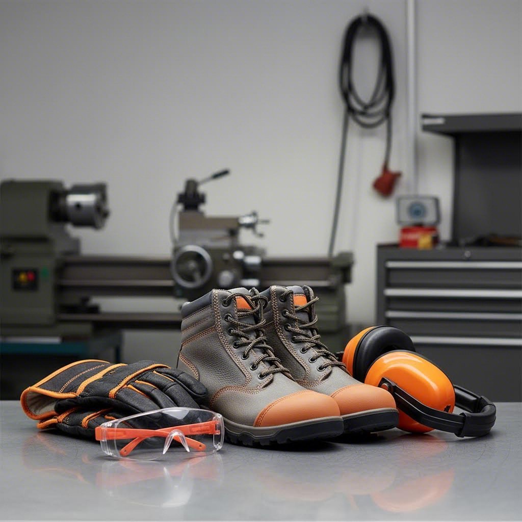
Essential PPE for Shearing Operations
Personal protective equipment forms your first line of defense when operating any industrial shear or metal cutting sheer. Surprisingly, failure to wear proper protection remains one of the most frequently cited OSHA standard violations in fabrication environments.
Every operator working with shear metal equipment should wear:
- Safety glasses or goggles: Flying metal fragments can cause serious eye injuries—ANSI Z87.1 rated protection is mandatory
- Heavy-duty gloves: Protect hands from sharp edges during material handling, but remove before operating controls to maintain dexterity
- Steel-toed boots: Heavy sheet metal dropping on unprotected feet causes crushing injuries
- Hearing protection: Prolonged exposure to sheer cutting noise can lead to permanent hearing loss—earplugs or earmuffs required
- Close-fitting clothing: Loose sleeves, jewelry, or dangling items can catch in moving machinery
- Long pants and sleeves: Protect skin from sharp metal edges and debris
Here's an important distinction: gloves protect during material handling but can become hazardous near moving controls. Operators should remove gloves when activating machine functions to maintain proper grip and tactile feedback on controls.
Machine Guarding and Safety Interlocks
Modern shearing machines incorporate multiple safety systems designed to prevent operator contact with the danger zone. According to MNOSHA guidance on shear safeguarding, acceptable point-of-operation protection must prevent operators from having any body part in the danger zone during the operating cycle.
Critical machine safety features include:
- Finger protectors: Physical barriers preventing hands from entering the space between upper and lower blades—never tamper with or remove these guards
- Light curtains: Photoelectric sensors that immediately stop blade motion when the invisible beam is broken
- Two-hand controls: Require both hands on controls positioned far from the cutting zone, ensuring the operator cannot reach the point of operation during the cycle
- Emergency stop buttons: Large, clearly marked buttons for immediate machine shutdown—operators should know their location instinctively
- Interlocked guards: Physical barriers that prevent machine operation when opened or removed
The Amada Shearing Machine Safety Guide specifically warns that the maximum opening height of finger protectors corresponds to the maximum worksheet thickness. Increasing this opening beyond specifications creates a serious crush hazard.
Lockout/Tagout procedures deserve special attention. Before any maintenance, blade changes, or clearing of jammed material:
- Disconnect primary power sources completely
- Apply lockout devices to energy isolation points
- Attach tags identifying who locked out the equipment and why
- Verify zero energy state before beginning work
- Never remove another person's lock without authorization
Safe Material Handling Procedures
Sharp edges and heavy sheets present hazards before cutting even begins. Proper handling techniques prevent injuries from cuts, strains, and crushing accidents.
Follow these material handling best practices:
- Inspect materials before handling: Check for sharp burrs, damaged edges, or unstable stacking
- Use mechanical assists: Forklifts, cranes, or vacuum lifters for sheets exceeding safe manual lifting weights
- Team lift heavy materials: Coordinate movements when manual handling is necessary
- Maintain clear pathways: Remove obstacles between material storage and the shearing machine
- Stack materials securely: Prevent shifting or sliding that could cause sheets to fall
- Handle cut pieces carefully: Freshly sheared edges are extremely sharp—use tongs or magnetic handlers when possible
Proper lighting in the work area significantly reduces accidents. Safety experts recommend energy-efficient LED lighting that provides bright, consistent illumination—poor visibility contributes substantially to on-the-job incidents.
Before each shift, operators should conduct pre-operation safety inspections covering:
- Blade condition and mounting security
- Guard presence and proper positioning
- Control functionality and responsiveness
- Hydraulic systems for leaks (on hydraulic machines)
- Emergency stop operation
- Work area cleanliness and organization
- Warning signage visibility and condition
Faded or missing warning signage represents another frequently cited OSHA violation. Regularly verify that all safety communications remain legible and properly positioned—never assume everyone remembers what that worn sign used to say.
Training extends beyond operators. Even employees who won't operate the shear should receive basic familiarization—understanding that flashing warning lights mean stay clear, for example. This awareness training helps ensure everyone in the shop recognizes potential hazards.
With safety protocols firmly established, the next consideration becomes economic: does investing in shearing equipment make financial sense for your operation, or would outsourcing deliver better value?
Cost Analysis and Outsourcing Decisions for Shearing Projects
Safety protocols are essential—but here's the question that ultimately drives most equipment decisions: does in-house shearing actually make financial sense for your operation? The answer isn't always obvious. Between equipment investment, ongoing maintenance, operator training, and hidden operational costs, the true economics of the sheet metal process require careful analysis.
Whether you're considering your first metal shearing and cutting machines or evaluating whether to expand existing capacity, understanding the complete cost picture prevents expensive mistakes. Let's break down the real numbers behind shearing steel and other materials.
Equipment Investment vs Outsourcing Economics
The initial investment for shearing equipment varies dramatically based on capacity and automation level. According to 2025 pricing data, here's what you can expect across different machine categories:
| Machine Type | Typical Investment Range | Best Suited For |
|---|---|---|
| Manual Hand Shearing Machine | $400 - $8,000 | Light-duty, small workshops |
| Treadle Shearing Machine | $5,000 - $15,000 | Medium-duty, manual operation |
| Hydraulic Shearing Machine | $10,000 - $350,000+ | High-capacity, industrial use |
| CNC Hydraulic Shearing Machine | $85,000 - $1,300,000+ | Automated, high-precision |
But the sticker price tells only part of the story. Industry analysis reveals that facility modifications—increased floor space, enhanced power supply systems, and proper ventilation—can add 15-40% to your initial expenditure.
Consider a mid-sized manufacturing operation spending $200,000 annually on outsourced metal shearing services. Investing $350,000 in in-house machinery plus $60,000 in annual operating costs creates a break-even point in under three years. After that payback period, the company not only eliminates outsourcing costs but gains increased flexibility and quality control.
Here are the key factors to weigh when comparing in-house versus outsourced shearing:
- Capital requirements: In-house operations demand significant upfront investment; outsourcing converts fixed costs to variable expenses
- Volume consistency: Predictable, high-volume work favors in-house; sporadic demand suits outsourcing
- Lead time control: Internal operations eliminate supplier dependencies and reduce wait times
- Quality oversight: Direct control over parameters, maintenance, and operator training
- Cash flow impact: Equipment ties up capital that might otherwise fund growth initiatives
Calculating True Per-Part Shearing Costs
Most manufacturers underestimate the total cost of ownership for shearing equipment. Looking only at equipment price ignores the ongoing expenses that accumulate over years of operation.
A comprehensive cost analysis must include:
- Initial purchase price: Base equipment cost plus delivery and installation
- Installation and training: Setup, calibration, and operator certification—often 5-10% of equipment cost
- Blade maintenance: Regular sharpening and replacement; high-quality blades cost $500-$3,000+ per set
- Energy consumption: Hydraulic systems particularly consume significant power during operation
- Downtime costs: Production losses during maintenance, breakdowns, or setup changes
- Labor expenses: Operator wages, benefits, and ongoing training requirements
- Consumables: Lubricants, hydraulic fluid, replacement wear parts
According to ROI analysis specialists, material efficiency gains from automated shearing typically achieve 3-5% better utilization than manually operated machines—translating directly to bottom-line savings on raw materials.
Labor represents another significant variable. Modern machine controls now handle complex calculations like cut blank size and sequence automatically. This technological shift means operators need less specialized sheet metal experience but must understand machine capabilities thoroughly. Hiring two skilled technicians might add $60,000-$80,000 to your annual payroll, but automation can allow one technician to oversee multiple processes simultaneously.
Here's a practical formula for calculating per-part costs:
Per-Part Cost = (Annual Equipment Cost + Labor + Maintenance + Consumables + Energy) ÷ Annual Parts Produced
For blanking sheet metal operations with high repeatability, automated systems deliver the lowest per-part costs once volume justifies the investment. However, low-volume or highly variable work may never achieve the throughput needed to amortize equipment expenses effectively.
When Professional Metal Shearing Services Make Sense
Despite the potential savings from in-house operations, outsourcing remains the smarter choice for many manufacturers. Consider professional metal shearing services when:
- Volume fluctuates significantly: Variable demand makes capacity planning difficult and equipment underutilization costly
- Specialized materials dominate: Exotic alloys or unusual thicknesses may require equipment you cannot justify purchasing
- Quality certifications are mandatory: Automotive, aerospace, and medical applications often require IATF 16949 or similar certifications that take years to achieve
- Capital constraints exist: Funds allocated to equipment might generate better returns invested elsewhere
- Rapid prototyping needs arise: Testing new designs benefits from service providers with flexible capabilities
For manufacturers producing precision components like chassis, suspension, and structural parts, partnering with IATF 16949-certified specialists offers compelling advantages. These certified manufacturers combine quality assurance systems with capabilities that would require massive internal investment to replicate.
Consider Shaoyi (Ningbo) Metal Technology as an example of what modern outsourcing partners offer: 5-day rapid prototyping, automated mass production, comprehensive DFM support, and 12-hour quote turnaround. For automotive supply chains where quality certification and speed matter, such partnerships eliminate capital equipment risk while maintaining production standards.
The hybrid approach often works best. Many successful operations maintain in-house shearing for high-volume standard work while outsourcing specialized jobs, overflow capacity, or prototype development. This strategy optimizes equipment utilization while maintaining flexibility for changing demands.
ROI Factors That Drive Profitability
When evaluating shearing investments, focus on these direct ROI drivers:
- Material waste reduction: High-precision machines can reduce scrap by up to 30%, directly boosting profitability
- Labor savings: Automated machines reduce manual intervention, lowering labor costs and minimizing errors
- Productivity gains: Faster cycle times and programmable operations increase throughput, enabling quicker order fulfillment
- Reduced outsourcing markups: Eliminating third-party margins saves 20-30% on previously outsourced parts
Indirect benefits compound these savings over time. Reliable machines with robust support minimize production interruptions. Consistent, burr-free cuts reduce secondary finishing requirements. And bringing shearing in-house can open new revenue streams—supplying fabricated parts to other businesses accelerates payback by improving equipment utilization.
The decision ultimately depends on your specific circumstances. A thorough cost analysis—accounting for all factors from initial investment through ongoing operations—reveals whether in-house shearing delivers genuine value or whether professional metal shearing services better serve your strategic objectives. With clear financial understanding established, optimizing your complete shearing workflow becomes the final piece of the puzzle.
Optimizing Your Sheet Metal Shearing Workflow
You've absorbed the technical knowledge, understood the equipment options, and grasped troubleshooting fundamentals—now it's time to bring everything together into a cohesive, repeatable process. A well-optimized shearing sheet metal workflow transforms scattered best practices into systematic excellence that delivers consistent results day after day.
Think of your workflow as a chain where every link matters. Rushing material preparation undermines parameter settings. Skipping quality checks allows defects to propagate downstream. But when each step receives proper attention, the entire sheet metal operations sequence flows smoothly from raw material to verified finished parts.
Pre-Shearing Material Preparation Steps
Quality shear metal cutting begins before the sheet ever touches your machine. Proper preparation prevents defects that no amount of parameter adjustment can fix after the fact.
Follow these essential preparation steps:
- Verify material specifications: Confirm alloy type, temper, and thickness match your job requirements. Material mix-ups cause parameter mismatches and scrapped parts.
- Inspect incoming sheets: Check for surface contamination, mill scale, edge damage, or warping that could affect cut quality or damage blades.
- Allow temperature stabilization: Materials arriving from outdoor storage need time to reach ambient shop temperature—thermal expansion affects dimensional accuracy.
- Clean cutting surfaces: Remove oils, debris, or protective coatings from the cutting zone. Contamination accelerates blade wear and compromises edge quality.
- Plan cutting sequences: Optimize nesting to minimize waste and reduce material handling between cuts.
- Calculate parameter settings: Determine appropriate blade clearance, hold-down pressure, and backstop positions before loading material.
According to quality assurance specialists, the positioning accuracy and reliability of the back gauge directly affect dimensional accuracy of blanking parts. Frequently checking for deformation and verifying parallelism with the blade prevents dimensional differences across production runs.
Quality Verification and Inspection Methods
How do you know your cuts actually meet specification? Systematic inspection catches problems early—before defective parts reach customers or downstream operations.
Implement these verification checkpoints throughout your plate shearing workflow:
- First-article inspection: Measure the initial cut piece against specifications before proceeding with production quantities. Verify dimensions, edge quality, and squareness.
- In-process sampling: Check random pieces periodically during production runs—blade wear and thermal drift can cause gradual quality degradation.
- Edge quality assessment: Examine cut edges for burrs, rollover, or roughness. Consistent edge appearance indicates stable parameters.
- Dimensional verification: Use calibrated measuring tools to confirm length, width, and diagonal measurements fall within tolerance.
- Flatness checks: Place cut pieces on a reference surface to detect bowing, twisting, or warping from the cutting process.
- Surface condition review: Inspect for hold-down marks, scratches, or contamination that could affect downstream processes.
Material quality variations can affect shearing outcomes even with consistent machine settings. Industry guidance recommends performing trial cuts and adjusting parameters before production whenever material source or batch changes—what worked perfectly yesterday may need fine-tuning today.
Optimizing Your Shearing Workflow
Beyond individual steps, workflow optimization considers how activities connect and flow together. Small improvements at each stage compound into significant productivity gains.
Here's the complete metal sheet shear workflow sequence for consistent results:
- Receive and stage materials: Organize incoming sheets by type, thickness, and job priority. Maintain clear identification throughout storage.
- Review job requirements: Confirm quantities, dimensions, tolerances, and any special handling instructions before beginning work.
- Prepare the sheetmetal sheer: Verify blade condition, check lubrication levels, and confirm safety systems function properly.
- Configure machine parameters: Set blade clearance, backstop position, and hold-down pressure appropriate for the specific material.
- Execute first-article cut: Process one piece and perform complete dimensional and quality verification before production.
- Run production quantities: Maintain consistent material positioning and feeding rates. Monitor for unusual sounds or vibrations.
- Perform in-process inspection: Sample parts at regular intervals to detect quality drift early.
- Complete final inspection: Verify the entire batch meets specifications before releasing to the next operation.
- Document results: Record any parameter adjustments, quality issues, or deviations for future reference.
- Prepare for next job: Clean the work area, return unused materials to storage, and ready the machine for subsequent operations.
For manufacturers seeking to streamline this entire sequence, partnering with certified specialists offers compelling advantages. Companies like Shaoyi (Ningbo) Metal Technology demonstrate how professional partners accelerate automotive supply chains—their 12-hour quote turnaround and 5-day rapid prototyping capabilities compress timelines that might take weeks to achieve internally. When producing precision chassis, suspension, and structural components, their comprehensive DFM support catches potential issues before production begins, while IATF 16949 certification ensures quality standards match the most demanding automotive requirements.
Whether you're performing shearing in-house or leveraging professional partners, the principles remain consistent: systematic preparation, careful parameter control, thorough inspection, and continuous documentation. Master this workflow, and you'll transform sheet metal shearing from an unpredictable operation into a reliable, repeatable process that delivers flawless cuts every time.
Frequently Asked Questions About Sheet Metal Shearing
1. What is the purpose of a sheet metal shear?
A sheet metal shear makes straight cuts in flat sheet metal by positioning material between two sharp blades and applying downward force. This cold mechanical cutting process separates metal cleanly without chip formation, melting, or heat distortion. Shears range from manual bench-mounted units for light fabrication to hydraulic industrial machines capable of cutting 25mm+ steel plate, making them essential for producing blanks, sizing sheets, and preparing materials for downstream fabrication operations.
2. What blade clearance should I use for shearing different metals?
Optimal blade clearance typically ranges from 5-10% of material thickness for most metals, but varies by material type. Mild steel requires 5-10% clearance, stainless steel needs 8-12% due to its hardness, and aluminum works best with tighter 4-6% clearance to prevent edge rollover. Incorrect clearance causes defects: too tight increases blade wear and cutting force, while too wide produces burrs and rough edges. Always calculate clearance based on your specific material and thickness combination.
3. How do I fix burr formation on sheared metal edges?
Burrs typically result from dull blades, excessive blade clearance, or blade misalignment. Start by inspecting blade edges for rounding or damage and replace or resharpen as needed. Reduce the gap between upper and lower blades if clearance exceeds 10-12% of material thickness. Verify parallel blade alignment across the entire cut length using precision measurement tools. For harder materials like stainless steel, consider upgrading to carbide-tipped blades designed for that specific application.
4. What is the maximum thickness a shearing machine can cut?
Maximum cutting thickness depends on both machine capacity and material type. Manufacturers rate machines using mild steel as the baseline. For harder materials, calculate actual capacity using this formula: Maximum Thickness = Rated Capacity × (Rated Tensile Strength ÷ Material Tensile Strength). A machine rated for 6mm mild steel can cut approximately 10.8mm aluminum but only 3.1mm of 304 stainless steel. Hydraulic guillotine shears handle the thickest materials, with some models exceeding 25mm mild steel capacity.
5. When should I outsource shearing instead of doing it in-house?
Outsource shearing when volume fluctuates significantly, specialized materials require equipment you cannot justify purchasing, or quality certifications like IATF 16949 are mandatory. Professional partners such as Shaoyi (Ningbo) Metal Technology offer 5-day rapid prototyping, automated mass production, and comprehensive DFM support without capital equipment investment. In-house operations make more sense for predictable high-volume work where equipment utilization remains consistently high and payback periods fall under three years.