 Small batches, high standards. Our rapid prototyping service makes validation faster and easier —

Sheet Metal Quality Secrets: What Suppliers Hope You Never Learn
Understanding Sheet Metal Quality Fundamentals
Ever wondered why some metal components last decades while others fail within months? The answer lies in something manufacturers don't always discuss openly: sheet metal quality. It's not just about shiny surfaces or straight edges—it's a complex interplay of factors that determine whether your finished product performs flawlessly or becomes a costly liability.
With the global sheet metal fabrication services market projected to reach $19.6 billion by 2030, understanding what separates exceptional fabrication from mediocre work has never been more critical for engineers, procurement specialists, and manufacturers alike.
What Defines Quality in Sheet Metal Manufacturing
Quality sheet metal isn't simply metal that "looks right." It's a measurable outcome spanning the entire production journey—from raw material selection through cutting, forming, welding, and final inspection. Think of it as a chain where every link must hold.
At its core, high quality sheet metal fabrication means producing components that meet exact dimensional and functional specifications consistently, batch after batch. This involves transforming flat metal sheets into parts that power complex systems across aerospace, automotive, electronics, and heavy equipment industries.
The four essential dimensions that define excellence include:
- Dimensional Accuracy: Parts must match specified dimensions precisely. Even slight deviations can cause components that don't fit together properly, leading to assembly issues or functional defects.
- Surface Finish: Beyond aesthetics, surface texture affects corrosion resistance, friction properties, and coating adhesion. Industry standards like ASME B46.1 specify exact roughness parameters.
- Material Integrity: The metal itself must meet specifications for composition, thickness, and mechanical properties. Improper material selection leads to cracking, warping, or premature failure.
- Structural Performance: Finished parts must withstand intended loads, environmental conditions, and operational stresses throughout their service life.
When manufacturers create with high-quality metal sheets as their foundation, they're building reliability into every component from the start.
Why Quality Standards Matter for End Products
Imagine installing a critical bracket in an aircraft—only to discover it fails under stress because tolerances weren't maintained during fabrication. The consequences extend far beyond replacement costs.
Quality sheet metal fabrication provides measurable benefits that ripple through entire supply chains:
- Reduced errors and rework, cutting production costs significantly
- Improved assembly efficiency when components fit together correctly
- Enhanced product durability and customer satisfaction
- Minimized material waste through precise manufacturing
- Compliance with industry regulations and safety requirements
Poor-quality detailing errors impact subsequent processes including welding, bending, and assembly—affecting both timelines and project costs. Conversely, rigorous quality control validates designs and ensures components perform exactly as intended.
The stakes are particularly high in industries like automotive and aerospace, where a single defective part can trigger recalls, safety incidents, or catastrophic failures. That's why understanding these fundamentals isn't optional—it's essential for anyone involved in specifying, purchasing, or manufacturing sheet metal components.
Industry Standards and Certifications That Define Excellence
Here's a question many buyers never think to ask: What certifications does your sheet metal supplier actually hold? And more importantly—what do those certifications really mean for the parts you receive?
Industry standards aren't just bureaucratic checkboxes. They represent proven frameworks that separate world-class fabricators from shops cutting corners. Understanding these standards gives you leverage when evaluating suppliers and helps you specify exactly what your application demands.
ISO and IATF Certification Requirements
The foundation of sheet metal quality standards begins with internationally recognized management systems. These certifications demonstrate that a fabricator has implemented systematic processes for maintaining consistency and driving continuous improvement.
ISO 9001:2015 serves as the baseline certification for quality-focused manufacturers. According to industry experts, this certification demonstrates that a company has implemented an effective quality system with proper procedures to continuously monitor and improve processes. For sheet metal fabrication quality control, ISO 9001:2015 translates to documented inspection protocols, calibrated measurement equipment, and traceable production records.
IATF 16949 builds upon ISO 9001 with automotive-specific requirements. If your components end up in vehicles, this certification is non-negotiable. It mandates advanced product quality planning (APQP), production part approval processes (PPAP), and failure mode analysis—all critical for sheet metal quality control in high-volume automotive production.
AS9100 applies similar rigor for aerospace applications. With tolerances often measured in thousandths of an inch and zero tolerance for defects, aerospace-certified fabricators maintain the most stringent sheet metal quality standards in the industry.
When searching for quality heating and sheet metal reviews or evaluating any fabrication partner, these certifications provide objective evidence of their commitment to excellence.
ASTM Specifications for Sheet Metal Materials
While management system certifications address how a shop operates, ASTM specifications define what materials must deliver. These standards ensure the raw materials entering fabrication meet precise chemical compositions, mechanical properties, and dimensional tolerances.
For sheet metal applications, key ASTM standards govern everything from basic carbon steel to specialized alloys:
- A568/A568M: General requirements for carbon and high-strength, low-alloy hot-rolled and cold-rolled sheet
- A240/A240M: Heat-resisting chromium and chromium-nickel stainless steel plate, sheet, and strip for pressure vessels
- A666: Annealed or cold-worked austenitic stainless steel sheet, strip, plate, and flat bar
- A480/A480M: General requirements for flat-rolled stainless and heat-resisting steel plate, sheet, and strip
These specifications matter because material properties directly affect formability, weldability, and finished part performance. A fabricator referencing correct ASTM standards demonstrates they understand material behavior—not just machine operation.
How Standards Translate to Shop Floor Requirements
Sounds complex? Let's break down what these certifications actually require in daily practice:
| Certification | Primary Focus | Industries Served | Key Shop Floor Requirements |
|---|---|---|---|
| ISO 9001:2015 | Quality Management Systems | All industries | Documented procedures, calibrated equipment, management reviews, corrective action processes |
| IATF 16949 | Automotive Quality Management | Automotive OEMs and suppliers | APQP, PPAP, FMEA, control plans, MSA, statistical process control |
| AS9100 | Aerospace Quality Management | Aerospace and defense | Configuration management, first article inspection, special process controls, counterfeit part prevention |
| AWS CWF | Welding Fabrication | Structural, pressure vessels | Certified welders, qualified procedures, weld inspection protocols |
| UL 1332 | Enclosure Durability | Electronics, industrial equipment | Corrosion testing, environmental durability validation, coating thickness verification |
For quality sheet metal inc operations and similar fabricators, maintaining these certifications requires ongoing investment in training, equipment calibration, and process documentation. The payoff comes through reduced defects, improved customer confidence, and access to demanding markets that require certified suppliers.
When evaluating quality heating and sheet metal reviews or any fabrication partner, ask to see current certification documents—and verify they cover the specific processes your project requires. A shop certified for cutting and forming may not hold welding certifications, leaving gaps in their quality system that could affect your final product.
Understanding these standards positions you to ask better questions, set clearer expectations, and ultimately receive components that perform as designed. But certifications only tell part of the story—the real test comes in how fabricators prevent and detect defects during actual production.
Common Sheet Metal Defects and How to Prevent Them
You've selected certified suppliers and specified the right materials. So why do defects still appear? The uncomfortable truth is that even well-managed fabrication shops encounter problems—the difference lies in whether they catch issues before parts ship or after they've reached your assembly line.
A thorough sheet metal quality inspection reveals defects that can compromise everything from fit and function to structural integrity. Understanding these failure modes—and their root causes—transforms you from a passive buyer into an informed partner who can prevent problems before they occur.
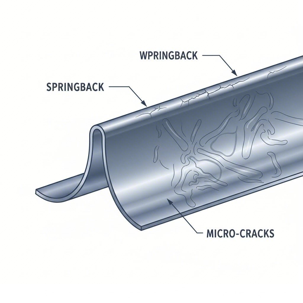
Springback and Dimensional Distortion Causes
Imagine bending a piece of metal to exactly 90 degrees, only to watch it spring back to 87 degrees the moment you release pressure. That's springback—and it's one of the most frustrating challenges in quality sheet metal fabrications.
Springback occurs because metal isn't perfectly plastic. When you bend sheet metal, you're creating both elastic and plastic deformation simultaneously. The elastic portion "remembers" its original shape and partially recovers once bending force is removed. According to manufacturing research, this phenomenon is particularly problematic with high-strength or thick materials.
Root causes of springback include:
- Material elasticity: Higher yield strength materials exhibit greater springback tendencies
- Bend radius: Tighter bends relative to material thickness increase elastic recovery
- Material thickness: Thicker sheets require more force and show more pronounced springback
- Grain direction: Bending perpendicular to grain structure affects deformation behavior
Prevention strategies for springback:
- Over-bend slightly beyond the target angle to compensate for elastic recovery
- Use specialized press brake equipment that applies consistent pressure
- Select materials with lower elasticity when dimensional precision is critical
- Apply heat treatments to reduce internal stresses before forming
- Implement bottom bending or coining techniques for tighter angle control
Any comprehensive sheet metal quality checklist should include verification of bend angles after springback—not just during forming.
Wrinkling and Cracking: The Forming Failures
When metal doesn't flow properly during forming, two opposite problems emerge: wrinkling when material compresses, and cracking when it stretches beyond capacity.
Wrinkling appears as wave-like formations, typically on the inside of bends or in areas experiencing compressive stress. Industry analysis confirms this issue is more common in thin sheet metals, especially when bending at tight radii. While wrinkles might seem cosmetic, they compromise structural integrity and create stress concentration points.
Wrinkling root causes:
- Insufficient blank holder pressure during deep drawing operations
- Excessive material in compression zones with nowhere to flow
- Improper die design that doesn't control material movement
- Material thickness too thin for the forming geometry
Cracking represents one of the most severe defects—actual fractures that weaken or destroy parts. Manufacturing experts note that cracking is especially common in brittle materials or when bending radius is too tight relative to thickness.
Cracking root causes:
- Stretching material beyond its tensile limits
- Bend radius too tight for material ductility
- Material defects including impurities or inclusions
- Cold working or strain hardening from previous operations
- Incorrect grain orientation relative to bend direction
Combined prevention strategies:
- Ensure bending radius matches material thickness and type—softer metals tolerate tighter bends
- Conduct material analysis before fabrication to understand ductility limits
- Apply gradual pressure during forming rather than sudden force
- Use proper lubrication to reduce friction and improve material flow
- Consider annealing operations between forming stages for complex parts
Surface Defects and Their Prevention
Not all defects affect structural performance—but surface problems can be equally costly. Burrs, scratches, and indentations trigger rejections, require rework, and damage your reputation with end customers.
Burrs are rough or sharp edges that form during cutting operations. According to fabrication specialists, burrs create assembly issues, safety hazards, and poor fit—problems that multiply across high-volume production runs.
Burr prevention methods:
- Maintain sharp, properly aligned cutting tools through regular inspection
- Optimize die clearance for material type and thickness
- Use precision cutting methods like waterjet or laser for critical edges
- Implement automated deburring as a standard post-processing step
Surface scratches and indentations result from handling damage, contamination, or tooling contact. These defects may not affect function but devastate appearance—critical for visible components or those requiring coating.
Surface defect prevention:
- Apply protective film during transport and processing
- Keep tooling surfaces clean and polished
- Use padded supports and proper storage to prevent contact damage
- Remove foreign materials from die surfaces before each production run
- Train operators in proper handling techniques
Organizations like hk quality sheet metal fabricators build defect prevention into standard operating procedures rather than relying on final inspection to catch problems. This proactive approach—addressing root causes rather than symptoms—separates quality sheet metal and welding operations from shops that simply react to failures.
Building Your Defect Prevention Strategy
Preventing defects requires systematic attention across multiple areas:
| Defect Type | Primary Root Cause | Key Prevention Action | Inspection Method |
|---|---|---|---|
| Springback | Material elasticity | Over-bend compensation | Angle measurement post-forming |
| Wrinkling | Compressive stress | Optimize blank holder pressure | Visual and tactile inspection |
| Cracking | Tensile overstress | Proper bend radius selection | Dye penetrant or visual exam |
| Burrs | Tool wear/clearance | Tool maintenance program | Edge inspection, feel test |
| Surface damage | Handling/contamination | Protective measures | Visual inspection under lighting |
The most effective hk quality sheet metal producers integrate these prevention strategies into every production stage—not as afterthoughts, but as fundamental process requirements. When you understand what causes defects, you can specify controls that prevent them and verify that suppliers maintain those controls consistently.
Of course, prevention alone isn't sufficient. Even the best processes require verification through proper inspection methods—which brings us to the critical question of how to measure and confirm quality in finished components.

Inspection Methods and Measurement Techniques Compared
You've invested in certified suppliers and implemented defect prevention strategies. But here's the uncomfortable reality: how do you actually verify that finished parts meet specifications? The inspection method you choose can mean the difference between catching problems early—and discovering them during final assembly.
Sheet metal quality inspection presents unique challenges that many manufacturers underestimate. Unlike machined parts with rigid geometries, formed sheet metal components flex, spring back, and deform under their own weight. Choosing the wrong measurement approach doesn't just waste time—it produces unreliable data that leads to bad decisions.
Choosing the Right Inspection Method for Your Parts
Not all inspection methods work equally well for every application. Understanding the strengths and limitations of each approach helps you match the right tool to your specific requirements.
Visual Inspection remains the first line of defense in any quality program. Trained operators examine parts for surface defects, obvious dimensional problems, and workmanship issues. It's fast, requires minimal equipment, and catches many obvious problems before they reach more expensive measurement stages.
However, visual inspection has clear limitations. It cannot verify precise dimensions, detect subtle springback, or quantify deviations. For critical applications, visual inspection serves as a screening step—not a final verification method.
Hand Tools and Calipers have been used for sheet metal measurement for over 300 years. According to metrology industry analysis, many manufacturers still rely on these basic instruments even as production becomes increasingly automated. Calipers measure individual dimensions quickly and affordably, making them suitable for spot checks and simple verification.
The drawback? Hand measurements are operator-dependent and time-consuming for complex parts with multiple critical features. They also struggle with curved surfaces and internal geometries common in formed sheet metal components.
Coordinate Measuring Machines (CMMs) represent the traditional gold standard for precision measurement. These systems probe individual points with exceptional accuracy and can be programmed for repeatable measurement routines.
Yet CMMs present significant challenges for sheet metal inspection. As industry experts note, CMMs are more expensive to run than newer systems and require sophisticated skills to operate. They're also difficult to use accurately on sheet metal parts because metal sheets often have a kerf or edge profile. If a CMM touches the edge at the top or bottom, the location can vary by as much as 0.1 mm, even on thin parts.
Additionally, CMMs require controlled environments with constant temperature and humidity, making shop-floor deployment impractical and increasing maintenance costs.
Checking Fixtures provide fast, repeatable go/no-go verification for high-volume production. According to Creaform's analysis, checking fixtures offer operator-friendly inspections with minimal training requirements. Parts simply drop into the fixture, and deviations become immediately apparent.
The catch? Every new part design requires a new fixture. This lack of versatility adds time and cost whenever designs change. Fixtures also wear over time, demanding regular calibration and maintenance. Their bulky nature creates significant storage costs, and custom fixture design becomes prohibitively expensive for short production runs.
3D Laser Scanning has emerged as a powerful alternative that addresses many limitations of traditional methods. Portable 3D scanners capture complete surface geometry quickly, enabling full-field comparison against CAD models rather than isolated point measurements.
Modern optical tracking systems like those from SCANOLOGY excel at springback analysis—comparing scan data with original CAD to quickly locate position and magnitude of dimensional deviations. This helps technicians identify root causes and guide mold repair efficiently.
However, laser scanners struggle with thin, shiny edges that characterize many sheet metal parts. Generating meaningful edge data requires scanning at right angles to the surface—a slow and skilled process that may still produce suboptimal measurements.
2D Optical Scanning offers an alternative for flat or near-flat sheet metal components. Automated 2D field-of-view systems can measure multiple parts with multiple dimensional characteristics simultaneously. Parts simply rest on a backlit glass table, and measurements complete in approximately 0.01 seconds—compared to roughly five minutes for full 3D scans.
Inspection Method Comparison at a Glance
| Method | Accuracy | Speed | Relative Cost | Best Applications | Key Limitations |
|---|---|---|---|---|---|
| Visual Inspection | Low (qualitative) | Very Fast | Very Low | Surface defects, obvious problems, initial screening | Cannot verify dimensions; operator-dependent |
| Hand Tools/Calipers | ±0.02-0.05 mm | Moderate | Very Low | Spot checks, simple dimensions, low-volume verification | Time-consuming for complex parts; operator variability |
| Coordinate Measuring Machine | ±0.001-0.005 mm | Slow | High | High-precision features, reference measurements, first article | Edge measurement issues; requires controlled environment; skilled operators needed |
| Checking Fixtures | Go/No-Go | Very Fast | Medium-High (per design) | High-volume production; key position verification | No versatility; new fixture required per design; wear/calibration needs |
| 3D Laser Scanning | ±0.02-0.05 mm | Moderate (5+ min) | Medium-High | Complex geometries; springback analysis; full-surface comparison | Poor on thin/shiny edges; mesh resolution tradeoffs |
| 2D Optical Scanning | ±0.01-0.03 mm | Very Fast (~0.01 sec) | Medium | Flat profiles; trimming lines; hole patterns; high-volume 2D parts | Limited to 2D features; not suitable for complex 3D forms |
Overcoming Measurement Challenges in Flexible Components
Here's what many inspection guides don't tell you: sheet metal parts behave differently than rigid machined components. Their flexibility creates measurement challenges that require specialized approaches.
Springback Compensation demands comparison between as-formed and as-designed geometry. 3D scanning technology proves particularly effective here, allowing engineers to precisely forecast springback amounts during product design and mold development. During mass production, comparing scan data with original CAD quickly locates deviations and guides corrective action.
Part Flexibility means components can deform under their own weight or from handling pressure. Traditional CMM contact probes may actually push thin sheet metal out of position, introducing measurement errors. Non-contact optical methods avoid this problem but require proper fixturing to hold parts in their intended orientation.
Fixturing Requirements often get overlooked until inspection problems emerge. Flexible parts need supports that replicate their installed condition—otherwise you're measuring a different geometry than what actually assembles. RPS (Reference Point System) alignment using features like holes and slots helps ensure scan data accurately represents functional positioning.
Edge Definition presents particular difficulties because sheet metal parts are largely defined by their edges—the very features that laser scanners struggle to capture accurately. Optical tracking systems with specialized edge modules and shadow-less auxiliary lighting help obtain closed features like holes and slots with higher accuracy.
Trimming Line Inspection verifies that cut edges match specifications—critical for ensuring parts fit correctly in final assembly without gaps or interference. Any irregular trimming lines indicate positioning deviations or feeding problems that require immediate correction to avoid production losses.
Matching Methods to Production Requirements
Selecting the right inspection approach depends on balancing multiple factors:
- Production volume: High-volume runs justify fixture investment or automated 2D scanning; low-volume work benefits from versatile 3D scanning
- Part complexity: Simple profiles suit 2D methods; complex 3D forms require full surface capture
- Accuracy requirements: Aerospace tolerances may demand CMM verification; general fabrication tolerances work with optical methods
- Design stability: Frequent design changes favor flexible scanning over dedicated fixtures
- Integration needs: Modern systems import CAD tolerances directly, automating report generation
For operations seeking high quality sheet metal fabrication manufacturer capabilities, investing in appropriate inspection technology matters as much as production equipment. A high quality adjustable sheet metal feeder ensures consistent material positioning—but without matching inspection capabilities, you cannot verify the results.
The trend toward Industry 4.0 makes closing the inspection loop increasingly critical. As metrology specialists observe, the more automated the production, the more important it is to close this loop and inspect output smartly, accurately, and reliably. Bringing inspection systems onto the factory floor—next to production machines—reduces transfer time and integrates manufacturing with quality processes.
Whether you're a high quality fabrication of sheet metal manufacturer or a buyer evaluating supplier capabilities, understanding inspection methods helps you ask better questions and set realistic expectations. But accurate measurement is only part of the equation—those measurements must relate to properly specified tolerances and dimensional requirements.
Tolerance Standards and Dimensional Requirements
You've measured your parts accurately—but how do you know if those measurements are actually acceptable? This is where tolerance standards become critical. Without clearly defined acceptance criteria, even precise measurements become meaningless numbers on an inspection report.
Here's what many engineers discover too late: tolerance specifications for sheet metal differ significantly from machined parts. The forming processes, material behavior, and functional requirements create unique challenges that standard machining tolerances simply don't address. Understanding these differences separates buyers who receive consistently usable parts from those constantly fighting fit issues during assembly.
Tolerance Specifications for Different Sheet Metal Processes
Each fabrication process introduces its own sources of variation. According to manufacturing experts, sheet metal tolerances typically range from ±0.005" to ±0.060"—but where your specific parts fall within that range depends entirely on the processes involved.
Material tolerances set the foundation before any fabrication begins. The raw sheet metal itself varies in both thickness and flatness:
- Thickness tolerance: The allowable deviation from specified material thickness—critical for stack-ups and tight clearances
- Flatness tolerance: Permissible variation from a perfectly flat surface—affects sealing, load distribution, and cosmetic appearance
Cold-rolled steel offers tighter thickness tolerances than hot-rolled material due to more controlled processing. For example, SPCC cold-rolled steel at 1.0-1.2 mm thickness holds ±0.08 mm tolerance for sheet widths under 1000 mm, while Q235 carbon steel at similar thickness allows ±0.17-0.19 mm—more than double the variation.
Fabrication tolerances then compound on top of material variation. Each operation adds its own dimensional uncertainty:
| Process | Standard Tolerance | High Precision Tolerance | Key Variables Affecting Accuracy |
|---|---|---|---|
| Laser Cutting (linear) | ±0.45 mm | ±0.20 mm | Material thickness, beam focus, thermal effects |
| Laser Cutting (holes) | ±0.45 mm | ±0.08 mm | Hole diameter relative to thickness, pierce quality |
| Bending (angular) | ±1.0° | ±0.5° | Material springback, tooling condition, operator skill |
| Bending (XYZ position) | ±0.45 mm | ±0.20 mm | Cumulative bend accuracy, material consistency |
| Welding (linear) | ±0.5 to ±2.0 mm | ±0.5 mm | Heat distortion, fixture accuracy, weld sequence |
| Welding (angular) | ±2.0° | ±1.0° | Thermal stress, joint design, cooling rate |
| Stamping | ±0.1 to ±0.5 mm | ±0.05 mm | Die wear, material properties, press consistency |
Notice how tolerances stack when multiple operations combine. A part that's laser cut and then bent accumulates variation from both processes. Industry research confirms that complex geometries with multiple bends typically require looser tolerances (±0.030") compared to simple, symmetrical parts (±0.010").
Material Thickness Tolerance Charts
Raw material variation often surprises engineers accustomed to working with bar stock or plate. Sheet metal thickness varies not just between batches but across individual sheets. Understanding these baseline variations helps you set realistic expectations for finished parts.
Aluminum Sheet Thickness Tolerances:
| Thickness (mm) | Width <1000 mm | Width 1000-1250 mm |
|---|---|---|
| 0.80-1.00 | ±0.04 mm | ±0.06 mm |
| 1.50-1.80 | ±0.06 mm | ±0.10 mm |
| 2.00-2.50 | ±0.07 mm | ±0.12 mm |
| 3.00-3.50 | ±0.10 mm | ±0.15 mm |
| 5.00-6.00 | ±0.20 mm | ±0.24 mm |
Stainless Steel Thickness Tolerances:
| Thickness (mm) | Width <1250 mm | Width 1250-2500 mm |
|---|---|---|
| 0.60-1.00 | ±0.030 mm | ±0.035 mm |
| 1.00-1.50 | ±0.035 mm | ±0.040 mm |
| 1.50-2.00 | ±0.040 mm | ±0.050 mm |
| 2.00-2.50 | ±0.050 mm | ±0.060 mm |
| 2.50-3.00 | ±0.060 mm | ±0.070 mm |
These tolerances apply to quality steel sheet metal before any fabrication occurs. When specifying tight finished dimensions, account for this baseline variation in your design calculations.
Applying GD&T to Formed Metal Components
Traditional plus/minus tolerancing works for simple dimensions—but sheet metal assemblies demand more sophisticated control. That's where Geometric Dimensioning and Tolerancing (GD&T) becomes essential.
According to ASME Y14.5 standards, GD&T allows designers to convey critical information about part function to fabricators and inspectors. While plus/minus tolerances control drawing dimensions, GD&T tolerances control part features—a crucial distinction for formed components.
Why GD&T matters for sheet metal:
- Parts vary in form (flatness, straightness), orientation (perpendicularity, angularity), location (position, concentricity), and runout
- Plus/minus dimensions struggle to address these variations without ambiguity
- GD&T connects tolerance specifications to how parts actually assemble and function
- Feature control frames communicate designer intent clearly to fabrication and quality teams
Consider a bracket with multiple mounting holes. Plus/minus tolerancing might specify each hole location individually—but this creates ambiguity about how holes relate to each other and to mounting surfaces. GD&T position tolerances establish clear datum reference frames, ensuring holes align correctly regardless of individual dimensional variation.
In an assembly, there is a chain of consequence—a stackup of variations permitted by the tolerances. Deviation of one part must not inhibit overall function of the mechanism, even as other parts in the assembly might also deviate.
For any high quality sheet metal fabricating manufacturer, understanding GD&T isn't optional—it's fundamental to producing parts that actually work in assembly.
Practical Acceptance and Rejection Criteria
Tolerances only matter when you define clear pass/fail criteria. Without explicit acceptance standards, inspection becomes subjective—and disputes become inevitable.
Establishing acceptance criteria requires considering:
- Functional requirements: What tolerances actually affect part performance versus those that are merely cosmetic?
- Assembly constraints: How much variation can mating parts accommodate before fit problems occur?
- Process capability: Can your supplier's equipment consistently hold specified tolerances?
- Cost implications: Tighter tolerances increase production costs—are they justified by functional needs?
ISO 2768 provides standardized general tolerances that simplify drawings by establishing default tolerance classes. The four classes—fine (f), medium (m), coarse (c), and very coarse (v)—let designers specify precision level without individually tolerancing every dimension.
| Dimension Range (mm) | Fine (f) | Medium (m) | Coarse (c) | Very Coarse (v) |
|---|---|---|---|---|
| 0.5 to 3 | ±0.05 | ±0.1 | ±0.2 | — |
| 3 to 6 | ±0.05 | ±0.1 | ±0.3 | ±0.5 |
| 6 to 30 | ±0.1 | ±0.2 | ±0.5 | ±1.0 |
| 30 to 120 | ±0.15 | ±0.3 | ±0.8 | ±1.5 |
| 120 to 400 | ±0.2 | ±0.5 | ±1.2 | ±2.5 |
High quality sheet metal part fabrication manufacturers understand that specifying tighter tolerances than necessary wastes money—while looser tolerances than required causes assembly failures. The goal is matching specifications to actual functional requirements.
Working with experienced fabricators who understand tolerance tradeoffs makes a significant difference. As industry specialists note, skilled fabricators know how to optimize part design to minimize tolerance stack-up, improving both precision and quality while controlling costs.
Whether you're a high quality steel sheet metal fabrication manufacturer or a buyer specifying requirements, clear tolerance standards form the foundation for quality. But defining tolerances is only the beginning—maintaining them throughout production requires systematic process control at every stage.

Process Control and Quality Checkpoints Throughout Production
You've defined your tolerances and inspection methods. But here's the question that separates reactive shops from proactive manufacturers: at what points during production do you actually verify quality? Waiting until final inspection to discover problems means scrapped parts, missed deadlines, and frustrated customers.
The most effective sheet metal fabricators embed quality checkpoints throughout their entire production flow—from the moment raw materials arrive until finished parts ship. This stage-gate approach catches deviations early when corrections are simple and inexpensive, rather than late when rework becomes costly or impossible.
Stage-Gate Quality Checkpoints in Production
Think of quality control as a series of gates that parts must pass through before proceeding. Each gate serves a specific purpose, and failing any checkpoint triggers investigation and corrective action before problems multiply.
According to manufacturing quality experts, effective quality control must govern all stages of fabrication and production—from initial drawings through shipping. Here's how leading fabricators structure their checkpoint systems:
-
Incoming Material Inspection
Quality starts before fabrication begins. Raw material verification prevents defective stock from contaminating your production line. This stage includes:
- Visual examination for surface defects, corrosion, or handling damage
- Thickness verification using calibrated micrometers or ultrasonic gauges
- Material certification review confirming chemical composition and mechanical properties
- Dimensional checks on sheet size and flatness
- Testing of elemental composition to avoid material mix-ups
Material that fails incoming inspection gets quarantined and returned—never entering production where it could cause downstream failures.
-
First Article Inspection (FAI)
Before running full production, the first completed part undergoes comprehensive verification against all drawing requirements. This critical gate confirms that:
- Machine setups produce parts within tolerance
- Tooling is properly aligned and functioning
- Process parameters match specifications
- Operators understand requirements correctly
Only after FAI approval does production proceed. This prevents entire batches from being manufactured incorrectly.
-
In-Process Checkpoints
Established inspection points during manufacturing maintain acceptable quality and spot variations before they impact final products. Key triggers for in-process inspection include:
- Initial setup verification for each operation
- Whenever tools or dies are changed
- At designated intervals during production runs
- Before and after critical forming operations
- Following any process interruption or adjustment
These checkpoints catch drift, tool wear, and operator errors in real-time—enabling immediate correction.
-
Weld Inspection Gate
For fabricated assemblies, welding quality requires dedicated verification. This checkpoint examines:
- Weld bead appearance and consistency
- Dimensional accuracy of welded assemblies
- Absence of cracks, porosity, or incomplete fusion
- Welder qualification verification for the specific procedure
Weld defects hidden beneath surfaces can cause catastrophic field failures—making this gate non-negotiable for structural components.
-
Final Inspection and Sampling
Before parts leave production, final verification confirms all requirements are met. According to industry standards, examining a statistically valid sample of the product lot determines if the entire lot meets customer quality requirements. A sampling plan typically includes:
- Which dimensions and features will be examined
- How many randomly selected parts per lot will be inspected
- Acceptance and rejection criteria for each characteristic
- Documentation requirements for inspection records
-
Packing and Shipping Verification
The final checkpoint ensures finished components are properly protected for transit. Each piece requires proper marking and identification, secure blocking to prevent damage, and appropriate packaging materials. A quality sheet metal heating and air system component that arrives damaged provides zero value—regardless of how precisely it was manufactured.
Implementing SPC for Consistent Results
Here's what most fabricators don't discuss openly: individual inspections only tell you about individual parts. They cannot predict whether your next part—or your next thousand parts—will meet specifications. That's where Statistical Process Control transforms quality management.
SPC is a systematic approach to monitoring and controlling processes through statistical analysis. According to manufacturing research, by collecting data in real-time during production, manufacturers can identify variations that could lead to defects before they actually occur. This proactive approach enables timely adjustments, ensuring production remains within desired specifications.
Why SPC Matters for Sheet Metal:
Unlike industries with highly automated processes, sheet metal fabrication involves numerous variables—material batch differences, tool wear, operator technique, environmental conditions. SPC provides the framework to:
- Detect trends before parts fail: Control charts reveal when a process drifts toward specification limits, allowing correction before defects occur
- Separate special causes from common causes: Understanding whether variation comes from the system or specific incidents guides appropriate responses
- Reduce over-inspection: Statistically capable processes require less intensive checking, reducing costs while maintaining confidence
- Drive continuous improvement: Data-driven analysis identifies root causes and validates improvement effectiveness
SPC in Sheet Metal Applications:
Consider a practical example of how SPC applies to sheet metal production:
Scenario: A fabricator implements SPC to monitor bend angles on a critical bracket.
The SPC process involves measuring sample parts at regular intervals, plotting results on control charts, and analyzing patterns. When measurements approach control limits—even while still within specification—operators investigate and adjust before producing defective parts.
Key parameters monitored through SPC in sheet metal operations include:
- Bend angles and dimensional accuracy
- Material thickness variation
- Hole position accuracy
- Surface finish measurements
- Weld penetration depth
Six Sigma and Sheet Metal Quality:
Six Sigma builds upon SPC foundations with a goal of near-perfect quality. According to materials engineering specialists, if ±6σ (twelve standard deviations) equals the difference between upper and lower specification limits, then only 3.4 out of 1,000,000 items produced will not meet specifications—essentially zero defects.
Achieving six sigma capability in sheet metal fabrication requires:
- Selecting materials with composition and properties compatible with processes
- Characterizing effects of incoming material variations on process output
- Controlling composition and property variations of incoming materials
- Selecting and controlling process conditions precisely
- Using failure analysis to identify root causes of problems
Companies like quality heating & sheet metal company inc that serve demanding industries understand this methodology isn't just theoretical—it's the foundation for reliable production at scale.
Benefits of Systematic Process Control
Implementing SPC yields measurable advantages for sheet metal manufacturers:
| Benefit | How SPC Delivers It | Impact on Operations |
|---|---|---|
| Improved Quality | Detects and minimizes defects early in production | Higher first-pass yield, fewer customer complaints |
| Cost Savings | Reduces scrap and rework through prevention | Lower material waste, improved profitability |
| Enhanced Efficiency | Proactive monitoring optimizes resource utilization | Less downtime, faster throughput |
| Customer Satisfaction | Consistent quality and specification adherence | Stronger relationships, repeat business |
| Regulatory Compliance | Documented evidence of process capability | Easier certification audits, market access |
Making SPC Work in Practice:
Implementing effective SPC requires commitment beyond simply collecting data. As quality experts note, it takes engineering focus and discipline to use data to make process and design improvements. Key success factors include:
- Management commitment to data-driven decision making
- Training operators to understand control charts and respond appropriately
- Investing in measurement systems capable of detecting meaningful variation
- Establishing clear escalation procedures when processes go out of control
- Regularly reviewing and updating control limits as processes improve
Whether you're evaluating a high quality precision sheet metal servo feeder for your production line or assessing supplier capabilities, understanding their process control maturity matters. Shops with robust SPC programs deliver more consistent quality than those relying solely on final inspection—catching and correcting problems before they become your problems.
Of course, all this process control generates significant documentation. Understanding what quality records you should expect—and what they tell you about supplier capabilities—becomes the next critical consideration.
Quality Documentation and Traceability Requirements
Here's an uncomfortable truth most suppliers won't volunteer: a quality part without proper documentation is essentially unverified. You might hold a perfectly manufactured component in your hands—but without the paperwork proving its origins, materials, and inspection results, you're accepting unquantified risk into your supply chain.
Documentation isn't bureaucratic overhead. According to material traceability specialists, the Mill Test Report is a claim about a piece of paper, not a guarantee about the physical steel sitting on your shop floor. Understanding what documentation to expect—and what it actually proves—separates informed buyers from those inheriting hidden supply chain risks.
Essential Quality Documentation for Traceability
Quality-focused fabricators compile what's known as a Quality Data Package (QDP)—a comprehensive record documenting every aspect of your order's production. According to metal fabrication experts, a QDP is a compilation of reports that documents the traceability of materials, processes, and certifications used to produce each line item in a customer's purchase order.
What should you expect in a complete documentation package? Here are the essential elements:
- Certificate of Conformance (CoC): Written attestation that finished parts meet all specified requirements—requires printed name, signature, and date
- Mill Test Reports (MTRs): Documentation of raw material chemical composition and mechanical properties as certified by the producing mill
- First Article Inspection (FAI) Reports: Comprehensive dimensional verification confirming parts match specifications before full production
- In-Process Inspection Records: Documentation of quality checks performed during manufacturing stages
- Final Inspection Reports: Verification that completed parts meet all dimensional and visual requirements
- Process Certifications: Records verifying proper use of heat treatments, coatings, passivation, and other special processes
- Welder Qualifications: Certification status for welders, weld inspectors, and weld procedures
- Deviation Reports: Documentation of any approved changes from original specifications
For custom quality sheet metal projects, this documentation creates an unbreakable audit trail linking finished components back to their source materials and production processes.
Material Certifications and Test Reports Explained
The Mill Test Report serves as your material's "birth certificate"—but understanding its limitations is equally important. As metrology experts explain, MTRs verify a material's physical and chemical properties, confirming the metal product complies with international standards.
A proper MTR includes:
- Heat number linking material to specific production batch
- Chemical composition analysis results
- Mechanical properties including yield strength and tensile strength
- Material grade designation
- Applicable ASTM or other standard specifications
However, here's what suppliers rarely mention: MTRs can become disconnected from physical material through supply chain errors. Material can be mislabeled at the mill, packaged incorrectly by distributors, or mixed up during transit. Once an error is introduced, every document associated with that material becomes a source of misinformation.
For custom quality sheet metal and welding applications—especially in aerospace, defense, or medical industries—leading fabricators supplement MTRs with Positive Material Identification (PMI) testing. This verification confirms that physical material actually matches its paperwork, providing empirical proof rather than documented assumptions.
What Buyers Should Demand from Suppliers
When evaluating custom quality sheet metal manufacturing partners, documentation capabilities reveal as much as production equipment. Ask potential suppliers:
- What documentation is included standard versus available upon request?
- How do you maintain traceability from raw material through finished parts?
- Do you perform incoming material verification beyond reviewing MTRs?
- Can you provide complete genealogy reports linking any part to its source material?
- How are deviation requests documented and approved?
For construction quality sheet metal and other demanding applications, comprehensive documentation isn't optional—it's your protection against liability, your evidence for regulatory compliance, and your foundation for continuous improvement.
Remember: a fabricator's investment in documentation systems directly reflects their commitment to quality. Suppliers who view paperwork as an afterthought likely treat quality the same way. Those who maintain disciplined, verifiable records demonstrate the systematic approach that produces reliable parts—not just once, but consistently across every order.

Selecting a Quality-Focused Sheet Metal Supplier
You've learned what quality looks like, how to measure it, and what documentation proves it. Now comes the decision that determines whether all that knowledge actually protects you: choosing the right supplier. This is where theory meets reality—and where many buyers make costly mistakes.
The challenge? Every fabricator claims quality commitment. Marketing materials feature impressive certifications and gleaming equipment. But as industry specialists note, if your supplier doesn't have the same priorities as you, it could be time to take a step back and re-evaluate. Finding the best quality sheet metal forming services requires looking beyond surface-level promises to evaluate actual capabilities.
Key Questions to Ask Potential Suppliers
Before signing purchase orders, probe deeper than most buyers dare. These questions reveal whether a supplier genuinely prioritizes quality—or simply talks about it:
- What certifications do you hold, and which processes do they cover? ISO 9001 is baseline. For automotive applications, IATF 16949 certification is essential. Verify certifications are current and actually apply to the work you need.
- How do you verify incoming material quality? Suppliers relying solely on Mill Test Reports accept documented assumptions. Quality leaders supplement with Positive Material Identification testing.
- What is your first article inspection process? Comprehensive FAI before production confirms setup accuracy. Ask to see sample FAI reports demonstrating thoroughness.
- How do you handle parts that fall outside specification? Accountability is the foundation of trust. Does the supplier take responsibility and work to improve—or make excuses?
- What is your typical quote turnaround time? Responsiveness signals organizational capability. Suppliers offering fast quote turnaround—some within 12 hours—demonstrate efficient internal systems.
- Do you offer Design for Manufacturability support? Proactive DFM feedback prevents quality problems before production begins by identifying tolerance issues, material concerns, and process limitations early.
- What is your on-time delivery performance? As experienced buyers emphasize, the real key is finding suppliers that hit the dates they commit to—certainty beats aggressive promises followed by missed deliveries.
Evaluating Supplier Quality Capabilities
Beyond asking questions, systematically assess supplier capabilities using this evaluation checklist:
| Evaluation Category | What to Verify | Red Flags |
|---|---|---|
| Certifications | ISO 9001, IATF 16949, AS9100 as applicable; current audit dates; scope coverage | Expired certifications; vague about scope; no third-party verification |
| Inspection Equipment | CMM capabilities; optical scanning; calibration records; environmental controls | Outdated equipment; no calibration schedule; shop-floor CMM without climate control |
| Documentation Systems | Complete QDP capability; traceability from material to finished part; electronic records | Manual-only records; incomplete traceability; documentation as afterthought |
| Process Control | SPC implementation; control charts in use; capability studies available | No statistical methods; inspection-only quality approach; reactive problem solving |
| Communication | Responsive to inquiries; proactive updates; technical expertise accessible | Slow responses; sales-only contacts; unable to discuss technical details |
| Prototyping Speed | Rapid prototyping capabilities; ability to iterate quickly; design feedback loops | Long prototype lead times; inflexible processes; no design support |
For automotive applications requiring high quality sheet metal enclosure components or precision structural parts, IATF 16949-certified manufacturers demonstrate the quality commitment your supply chain demands. Suppliers like Shaoyi exemplify this standard—offering 5-day rapid prototyping, comprehensive DFM support, and 12-hour quote turnaround for chassis, suspension, and structural components.
Assessing Long-Term Partnership Potential:
Quality relationships extend beyond individual orders. According to fabrication experts, customer service is crucial when building long-term relationships with your metal fabrication partner. Evaluate these partnership indicators:
- Investment in technology: Suppliers modernizing equipment and staying current with industry advancements demonstrate commitment to improvement
- Workforce expertise: Companies with skilled, qualified craftsmen deliver higher-quality work consistently
- Willingness to take challenges: Does the supplier shy away from difficult projects—or embrace them? Growing your business means incorporating new materials or technologies
- Financial stability: Long-lasting partnerships require suppliers with financial strength to support stability over time
When sourcing from global suppliers, consider that a china quality sheet metal manufacturer meeting international certification standards—particularly IATF 16949 for automotive—has demonstrated capability to serve demanding markets worldwide. Similarly, china high quality sheet metal parts suppliers with documented quality systems offer competitive options for buyers willing to verify capabilities rather than assume limitations.
Making Your Final Decision:
The best quality sheet metal nibbler in the world won't help if your supplier can't produce consistent parts. Similarly, owning the best quality sheet metal snips doesn't matter if incoming components don't fit together properly. Your supplier selection determines the quality foundation for everything downstream.
Ultimately, selecting a quality-focused supplier isn't about finding the lowest price or fastest promise. It's about identifying partners whose quality systems, capabilities, and values align with your requirements. The time invested in thorough evaluation pays dividends through fewer defects, more reliable deliveries, and supply chain relationships built on verified performance rather than hopeful assumptions.
Frequently Asked Questions About Sheet Metal Quality
1. How to check sheet metal quality?
Sheet metal quality verification involves multiple methods depending on your requirements. Start with visual inspection for surface defects like scratches, dents, and corrosion. Use calipers or micrometers for thickness verification. For dimensional accuracy, employ CMMs or 3D laser scanning to compare parts against CAD specifications. Cupping tests evaluate ductility and paint adhesion. For critical applications, implement incoming material verification with Positive Material Identification testing to confirm material composition matches documentation. IATF 16949-certified manufacturers like Shaoyi integrate comprehensive inspection protocols throughout production for automotive-grade quality assurance.
2. What is the best material for sheet metal fabrication?
The best material depends on your application requirements. Mild or low carbon steel remains the most common choice due to its excellent strength-to-cost ratio and fabrication ease. Stainless steel offers superior corrosion resistance for harsh environments. Aluminum provides lightweight properties ideal for aerospace and automotive applications. For high-strength needs, consider high-strength low-alloy (HSLA) steel. Always evaluate factors including corrosion resistance, formability, weldability, cost, and end-use conditions. Quality fabricators verify material certifications through Mill Test Reports and may supplement with PMI testing for critical applications.
3. How to tell the quality of metal?
Metal quality assessment combines documentation review with physical testing. Review Mill Test Reports verifying chemical composition and mechanical properties. Perform visual examination for surface defects, discoloration, or corrosion. Use calibrated instruments to verify thickness tolerances. Conduct hardness testing to confirm material properties. For critical applications, Positive Material Identification testing confirms actual composition matches documentation. Evaluate grain structure and check for inclusions or porosity that indicate manufacturing defects. Certified suppliers provide comprehensive quality data packages documenting material traceability from mill to finished part.
4. What are the most common sheet metal defects and how can they be prevented?
Common sheet metal defects include springback (elastic recovery after bending), wrinkling (compression-induced waves), cracking (tensile overstress), burrs (rough cutting edges), and surface scratches. Prevent springback through over-bending compensation and proper tooling selection. Avoid wrinkling by optimizing blank holder pressure and die design. Prevent cracking by selecting appropriate bend radii for material thickness and ductility. Minimize burrs through sharp, properly aligned cutting tools and optimized die clearance. Protect surfaces with films during handling and maintain clean tooling. Quality fabricators implement systematic defect prevention at each production stage.
5. What certifications should a quality sheet metal supplier have?
Essential certifications depend on your industry. ISO 9001:2015 serves as the baseline quality management certification for all industries. Automotive applications require IATF 16949, which mandates advanced product quality planning and statistical process control. Aerospace components demand AS9100 certification with stringent configuration management. AWS certifications verify welding capabilities. Beyond certifications, evaluate inspection equipment calibration records, documented quality procedures, material traceability systems, and SPC implementation. Manufacturers like Shaoyi maintain IATF 16949 certification with comprehensive DFM support and rapid prototyping capabilities for demanding automotive applications.