 Small batches, high standards. Our rapid prototyping service makes validation faster and easier —

Sheet Metal Machining Decoded: From Material Choice To Precision Cuts
What Sheet Metal Machining Actually Means
Ever wondered why searching for "sheet metal machining" returns such confusing results? You're not alone. The manufacturing world often uses this term interchangeably with metal fabrication, creating unnecessary confusion for engineers, designers, and procurement specialists alike. Let's clear this up once and for all.
So, what is sheet metal in the context of machining? Sheet metal refers to thin, flat pieces of metal—typically ranging from 0.006" to 0.25" in thickness—that serve as workpieces for various manufacturing operations. When we talk about sheet metal machining specifically, we're referring to CNC-controlled subtractive processes performed on these thin metal workpieces.
Defining Sheet Metal Machining Operations
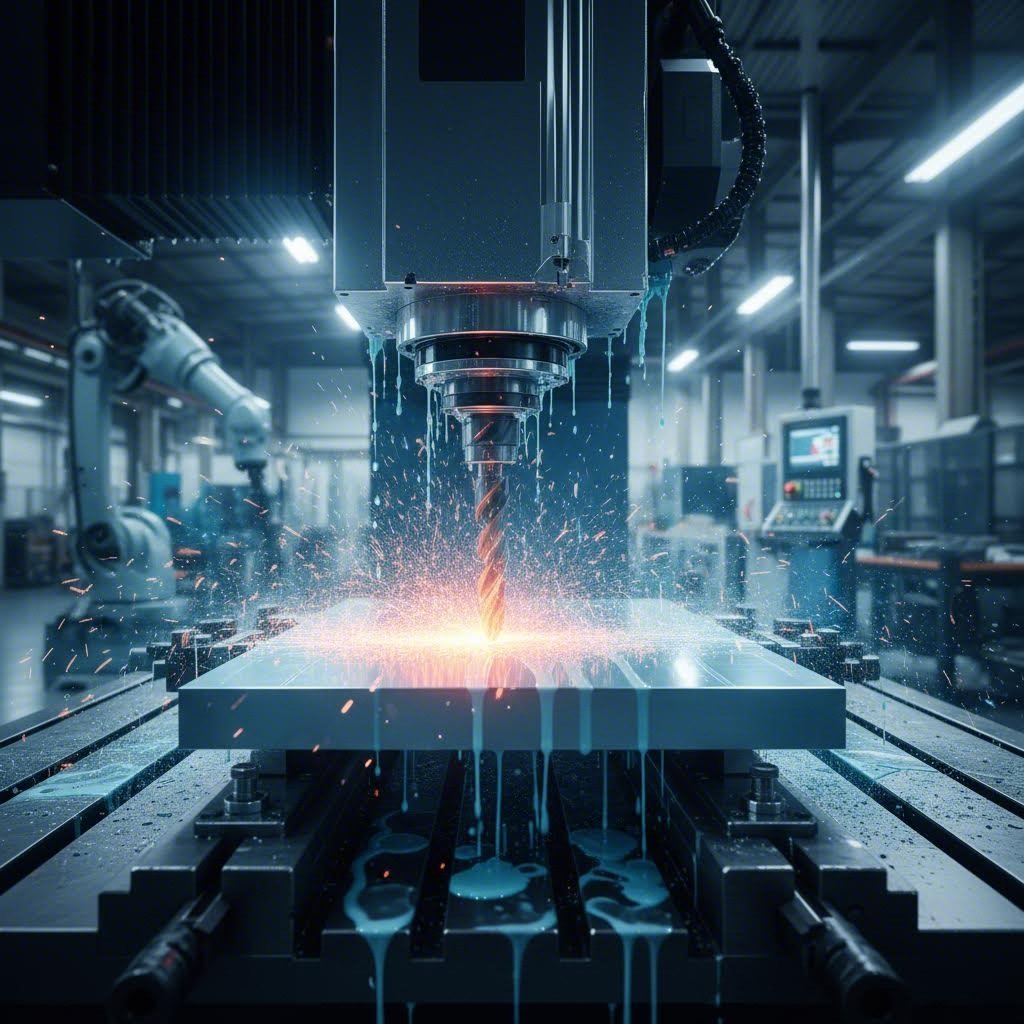
Sheet metal machining encompasses precision CNC operations that remove material from sheet metal workpieces to create specific features. The CNC meaning here is crucial—Computer Numerical Control allows programmed cutting tools to execute precise movements, creating features impossible to achieve through forming alone.
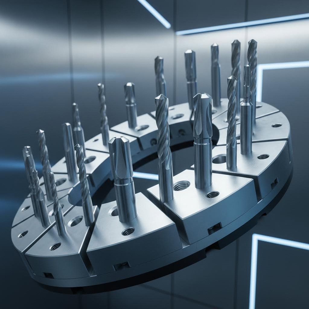
These operations include:
- Milling: Creating pockets, contours, and surface profiles on sheet metal surfaces
- Drilling: Producing precise holes at exact locations
- Tapping: Cutting internal threads for fastener insertion
- Countersinking: Creating recessed areas for flush-mounted fasteners
When performing sheet metal work that requires tight tolerances or complex integrated features like threads and grooves, these machining operations become essential. According to ProtoSpace Mfg, CNC machining offers superior strength with tighter tolerances and better surface finishes compared to fabrication-only approaches.
How Machining Differs from Fabrication
Here's where the confusion typically starts. Metal fabrication and machining aren't the same thing—though they're often used together in real-world manufacturing.
The fabrication of metal involves shaping sheet material through cutting, bending, and joining operations without necessarily removing material. Sheet metal machining, by contrast, uses CNC-controlled tools to selectively cut away material, creating precise features with tight tolerances.
Think of it this way: fabrication shapes the overall form through processes like laser cutting, bending, and welding. Machining refines that form by adding precision features—threaded holes, milled pockets, or countersunk recesses that fabrication simply cannot produce.
Consider an electronics enclosure. The basic box shape comes from sheet metal fabrication—cutting flat patterns and bending them into form. But those precisely threaded mounting holes for circuit boards? That's where machining enters the picture. The combination of both processes enables manufacturers to create parts with simple external geometries but complex, precision-machined features.
Understanding this distinction helps you communicate more effectively with manufacturers and make informed decisions about which processes your parts actually require. Throughout this guide, you'll discover exactly when machining operations become necessary and how to optimize your designs for both processes.
Core CNC Operations for Sheet Metal Parts
Now that you understand what separates machining from fabrication, let's dive into the specific CNC operations that transform flat sheet metal into precision-engineered components. Each operation serves a distinct purpose, and knowing when to apply each one can mean the difference between a functional part and an expensive paperweight.
When machining sheet metal, you're working with thinner material than typical CNC workpieces. This creates unique challenges—and opportunities. The key is matching the right operation to your feature requirements while respecting the material's thickness limitations.
CNC Milling on Sheet Metal Surfaces
Milling might seem counterintuitive for thin materials, but it's surprisingly effective when you need features that cutting and bending simply can't deliver. CNC milling on sheet metal creates pockets, surface contours, and recessed areas with remarkable precision.
Imagine you need a shallow pocket to nest an electronic component flush with your enclosure surface. Laser cutting won't help—it cuts through, not into. Bending? That's a different geometry entirely. Text milling for part identification or branding also falls into this category, creating engraved features directly into the metal surface.
The critical consideration with sheet milling is depth control. Remove too much material, and you compromise structural integrity. Most shops recommend leaving at least 40% of the original thickness as your floor when milling pockets in sheet metal. For a 3mm aluminum sheet, that means your maximum pocket depth should stay around 1.8mm.
Surface finish expectations differ from thick-stock machining too. The inherent flexibility of thin material can create chatter marks if feeds and speeds aren't optimized. Experienced machinists adjust spindle speeds upward and reduce cutting depths to compensate, often achieving surface finishes of Ra 1.6 μm or better on aluminum sheets.
Drilling and Tapping Operations
Here's where things get practical. Most sheet metal parts require holes—for fasteners, wiring, ventilation, or assembly alignment. But not all holes are created equal.
Standard drilling creates through-holes with typical tolerances of ±0.05mm when using CNC equipment. Consulting a drill bit size chart becomes essential when designing for specific fasteners, as hole-to-fastener fit directly impacts assembly quality. The drill size chart you reference should account for material—aluminum requires slightly larger clearance holes than steel due to thermal expansion differences.
Tapping takes those drilled holes and adds internal threads, transforming simple openings into functional fastening points. According to SendCutSend's tapping guidelines, hole sizes per tap size are process-specific—always reference your manufacturer's drill chart rather than generic tables when planning tapped features.
One critical limitation: tool access. When adding tapped holes, ensure sufficient clearance for the tap and collet to reach the feature. Nearby geometry—walls, bends, adjacent features—can restrict access and make tapping impossible without design modifications.
Countersinking deserves special attention for sheet metal applications. This operation creates the angled recess that allows flat-head screws to sit flush with your part surface. Design guidelines recommend avoiding countersinks in aluminum sheet under 3mm thick—the material deforms during machining, creating uneven screw seating. Stainless steel handles 2.5mm minimum due to higher strength.
The relationship between CNC programming and these operations matters for efficiency. Modern machining centers can perform drilling, tapping, and countersinking in a single setup, reducing handling time and maintaining positional accuracy between related features.
| Operation | Typical Applications | Achievable Tolerance | Ideal Sheet Thickness |
|---|---|---|---|
| CNC Milling | Pockets, contours, surface profiles, text engraving | ±0.025mm | 2.0mm – 6.0mm |
| Drilling | Through-holes, clearance holes, pilot holes | ±0.05mm | 0.5mm – 6.0mm+ |
| Tapping | Threaded holes for fasteners (M2-M10 common) | Thread class 6H/6G | 1.5mm minimum (material dependent) |
| Countersinking | Flush-mount fastener recesses | ±0.1mm depth, ±0.2mm diameter | 2.5mm+ stainless, 3.0mm+ aluminum |
Notice how each operation has its sweet spot for sheet thickness. Attempting to tap M5 threads in 1mm aluminum? That's a recipe for stripped threads and scrapped parts. The table above reflects real-world limitations that separate successful projects from frustrating failures.
Understanding these core operations prepares you to make informed decisions about your designs—but material choice affects how each operation performs. Different metals behave differently under CNC tooling, and that's exactly what we'll explore next.
Material Selection for Machined Sheet Metal
You've mastered the core CNC operations—now comes the question that can make or break your project: which material should you actually machine? Different types of sheet metal behave dramatically differently under cutting tools, and choosing the wrong one leads to excessive tool wear, poor finishes, or outright failure.
Understanding how different sheet metal types respond to machining operations isn't just academic—it directly impacts your tolerances, surface quality, production costs, and lead times. Let's break down the most common materials and what makes each one unique on the CNC machine.
Aluminum Sheet Machining Characteristics
If you're looking for the easiest material to machine, aluminum sheet metal wins hands down. Its soft nature and excellent thermal conductivity make it a favorite among machinists for good reason.
Aluminum alloys like 6061 and 5052 cut cleanly with minimal tool wear. According to Penta Precision, aluminum is easier on both tools and machines, leading to faster turnaround times with fewer tool changes. The material's high thermal conductivity—ranging from 138 to 167 W/m·K for common alloys like 5052 and 6061—means heat dissipates quickly from the cutting zone, preventing the thermal damage that plagues other materials.
What does this mean for your projects? Higher cutting speeds, longer tool life, and lower machining costs. For drilling and tapping operations, aluminum sheet allows aggressive feed rates without sacrificing hole quality. Milled pockets come out clean with minimal burring.
Thickness recommendations for aluminum sheet machining:
- Milling: 2.0mm minimum for pocket features; maintain 40% floor thickness
- Drilling: Effective from 0.5mm and up with proper backing support
- Tapping: 1.5mm minimum for M3 threads; 2.0mm+ recommended for reliability
The tradeoff? Aluminum's softness makes it prone to scratching during handling and can create gummy chip buildup on tools if coolant isn't applied properly. Aerospace-grade 7075 aluminum offers higher strength but reduced machinability compared to 6061.
Stainless Steel Machining Challenges
Now for the challenging one. Stainless steel sheet metal—particularly 316 stainless steel—presents machining difficulties that surprise engineers unfamiliar with its behavior.
The primary culprit? Work hardening. As cutting tools pass over stainless steel, the surface layer hardens progressively, making each subsequent pass more difficult than the last. According to PTSMAKE's machining guide, this creates a vicious cycle: harder material requires more cutting force, generating more heat, which causes even more hardening.
Add poor thermal conductivity to the mix—approximately 16.2 W/m·K for 316 stainless, roughly one-third that of aluminum—and heat concentrates at the cutting edge instead of dissipating. Tool wear accelerates dramatically, and dimensional accuracy suffers as the workpiece expands from trapped heat.
Key properties affecting stainless steel machinability:
- Hardness: Higher than aluminum; increases during cutting due to work hardening
- Thermal conductivity: Poor heat dissipation concentrates thermal stress at tool edges
- Chip formation: Stringy, tough chips that wrap around tools and mar surfaces
- Tensile strength: Up to 580 MPa for 316 grade, demanding robust tool setups
Successful stainless steel sheet machining requires slower cutting speeds—typically 30-50% lower than aluminum—sharp carbide tools with appropriate coatings, and abundant coolant delivery. For tapping operations, expect tool life roughly 40-60% shorter compared to aluminum.
Thickness considerations become even more critical with stainless. Minimum 2.5mm is recommended for countersinking operations, and tapped holes require sufficient thread engagement—typically 1.5x the thread diameter—to prevent stripping in this harder material.
Mild Steel and Specialty Materials
Between aluminum's ease and stainless steel's difficulty sits mild steel (cold-rolled steel). It offers good machinability with moderate tool wear, making it a practical middle-ground choice for many applications.
Cold-rolled steel machines predictably with standard tooling and doesn't work harden as aggressively as stainless grades. The main consideration? Corrosion protection. Unlike stainless or aluminum, mild steel requires surface treatment after machining to prevent rust—painting, powder coating, or galvanizing.
For specialty applications, copper sheet delivers excellent machinability with superior thermal and electrical conductivity. It's ideal for heat exchangers and electrical components but costs significantly more than steel alternatives. Galvanized steel presents a unique challenge: the zinc coating can create sticky residue on cutting tools, requiring more frequent cleaning during machining operations.
The bottom line? Material selection directly determines your machining parameters, tooling requirements, and project costs. Aluminum sheet gets you speed and economy. Stainless steel sheet metal delivers corrosion resistance at the cost of machining difficulty. And mild steel offers a balanced approach when surface treatment is acceptable.
With material behavior understood, you're ready to evaluate whether machining is even the right process for your specific features—or whether laser cutting, punching, or a hybrid approach makes more sense.
Choosing Between Machining and Other Methods
You've selected your material and understand the machining operations available—but here's the question that keeps engineers up at night: is CNC machining actually the right choice for your sheet metal parts? Sometimes a laser cutter handles the job faster. Other times, punching delivers better economics. And occasionally, combining multiple processes outperforms any single approach.
The sheet metal fabrication process offers multiple pathways to similar end results, but each method excels under different conditions. Making the wrong choice means wasted time, inflated costs, or compromised quality. Let's build a practical decision framework that removes the guesswork.
Machining vs Laser Cutting Decision Factors
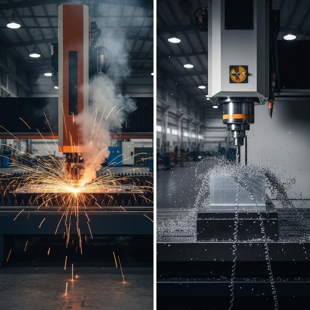
Laser cutting and CNC machining often compete for the same projects—but they're fundamentally different technologies solving different problems.
A laser cutter uses focused light energy to slice through material along a programmed path. According to Steelway Laser Cutting, industrial CNC laser cutters are extremely accurate and significantly decrease the likelihood of error when producing high-volume parts. The process excels at creating complex 2D profiles—intricate cutouts, detailed patterns, and tight-radius curves that would destroy mechanical cutting tools.
But here's the catch: laser cutting only cuts through. It cannot create threaded holes, milled pockets, or countersunk recesses. If your part requires any feature that exists within the material rather than passing completely through it, machining becomes necessary.
Consider these decision factors when comparing the two approaches:
- Feature type: Through-cuts favor laser; pockets, threads, and partial-depth features require machining
- Material behavior: Aluminum and copper reflect laser light, making them slower to cut; stainless steel cuts cleanly with laser
- Edge quality: Laser creates a heat-affected zone and kerf (material lost to the cutting process); machining produces cleaner edges without thermal distortion
- Tolerance requirements: Machining achieves ±0.025mm; laser cutting typically holds ±0.1mm to ±0.2mm
The kerf—that narrow channel of vaporized material left by the laser beam—matters more than you might think. For precision assemblies where parts interlock or nest together, the 0.1-0.3mm kerf width affects fit. Machined edges have no kerf, maintaining exact dimensional integrity.
What about cost? Laser cutting wins on speed for simple profiles, especially in thinner materials. A metal cutter using laser technology can produce dozens of flat parts in the time it takes to machine one. But add threaded holes or milled features, and the economics shift—parts must move from laser to machining anyway, adding handling time and setup costs.
Punching and Waterjet Alternatives
Laser cutting isn't your only alternative. Punching and waterjet cutting each occupy distinct niches in the metal fabrication process.
A die cut machine—whether a turret punch or dedicated stamping press—excels at high-volume production of consistent features. Punching creates holes, slots, and simple shapes by forcing hardened steel tools through sheet material. The process is fast, economical for large quantities, and produces clean edges without heat-affected zones.
The limitation? Punching only creates shapes matching available tooling. Custom profiles require custom dies, adding significant upfront cost. For prototype work or low-volume production, this tooling investment rarely makes sense. Punching also struggles with thick materials—most shops limit operations to 6mm steel or equivalent.
Waterjet cutting offers a unique middle ground. High-pressure water mixed with abrasive particles cuts virtually any material without thermal distortion. There's no heat-affected zone, no work hardening, and minimal kerf. According to Scan2CAD's manufacturing guide, CNC waterjet cutting machines can switch between pure water and abrasive-enhanced cutting based on material properties—ideal for mixed-material assemblies.
Waterjet particularly shines for thick materials (25mm+), heat-sensitive alloys, and composites that would damage laser optics. The tradeoff is speed—waterjet runs significantly slower than laser cutting for thin sheet metal and requires more post-processing to address surface texture from abrasive impact.
When Hybrid Manufacturing Makes Sense
Here's the insight that separates experienced engineers from newcomers: the best solution often combines multiple processes rather than forcing one method to do everything.
Hybrid manufacturing leverages each process for what it does best. NAMF's integration guide explains that combining fabrication and machining "leverages the strengths of both methods," enhancing efficiency while reducing production time. A typical hybrid workflow might laser-cut the blank profile, form bends on a press brake, then machine threaded holes and precision features on a CNC mill.
Consider an electronics enclosure requiring:
- Complex perimeter shape with ventilation slots
- Four precisely located M4 tapped mounting holes
- Countersunk holes for flush-mounted cover screws
- Bent flanges for assembly
No single process handles all these requirements efficiently. Laser cutting creates the perimeter and ventilation pattern in seconds. Press brake forms the flanges. CNC machining adds the threaded holes with ±0.05mm positional accuracy that laser cutting can't match. The hybrid approach delivers faster than machining everything and more precisely than laser-only production.
The key is understanding handoff points. Parts must maintain datum references between processes—locating features established during cutting that the machining operation references for precise hole placement. Experienced fabricators design these datum schemes into the initial blank, ensuring seamless transitions between processes.
Decision Matrix: Selecting Your Process
Use this comprehensive comparison to match your project requirements with the optimal manufacturing approach:
| Criteria | CNC Machining | Laser Cutting | Punching | Waterjet | Hybrid Approach |
|---|---|---|---|---|---|
| Tolerance Capability | ±0.025mm (best) | ±0.1mm typical | ±0.1mm | ±0.1mm | ±0.025mm on machined features |
| Feature Complexity | 3D features, threads, pockets | 2D profiles only | Standard shapes only | 2D profiles only | Full 3D capability |
| Ideal Thickness Range | 1.5mm – 12mm | 0.5mm – 20mm | 0.5mm – 6mm | 6mm to 150mm+ | Application dependent |
| Best Volume Range | 1 – 500 parts | 1 – 10,000+ parts | 1,000+ parts | 1 – 500 parts | 10 – 5,000 parts |
| Relative Cost (Low Volume) | Medium-High | Low-Medium | High (tooling) | Medium | Medium |
| Relative Cost (High Volume) | High | Low | Lowest | High | Low-Medium |
| Heat-Affected Zone | None | Yes | None | None | Varies by process |
| Lead Time | Medium | Fast | Fast (with tooling) | Slow | Medium |
Reading this matrix, patterns emerge. Need threaded holes with tight positional tolerances? Machining is non-negotiable—no other process creates threads. Producing 5,000 identical brackets with simple holes? Punching delivers lowest per-part cost once tooling is amortized. Cutting 50mm aluminum plate? Waterjet is your only practical option.
The hybrid column deserves special attention. When your part combines simple profiles with precision features, splitting the work between processes often costs less than forcing one method to handle everything. The sheet metal fabrication process becomes a coordinated workflow rather than a single-operation bottleneck.
With your manufacturing method selected, the next critical consideration becomes precision—specifically, what tolerances are actually achievable and how to specify them correctly for your application.
Precision Standards and Tolerance Capabilities
You've chosen your material and selected the right manufacturing method—but can the process actually deliver the precision your design demands? This question trips up even experienced engineers. Understanding achievable tolerances before finalizing designs prevents costly surprises during production and ensures your parts function as intended.
Here's what most resources won't tell you: tolerance capabilities in sheet metal machining differ significantly from thick-stock CNC work. The inherent flexibility of thin materials, combined with fixturing challenges, creates unique precision considerations that directly impact your design decisions.
Achievable Tolerances by Operation Type
Each machining operation delivers different precision levels. Knowing these limits helps you specify realistic tolerances—tight enough for function, loose enough for economical production.
Milling operations on sheet metal achieve the tightest tolerances, typically ±0.025mm for positional accuracy and feature dimensions. However, depth control presents challenges. According to Komacut's tolerance guide, standard linear tolerances for sheet metal work fall around ±0.45mm, with high-precision work achieving ±0.20mm. When milling pockets, expect slightly wider depth tolerances—±0.05mm is realistic for controlled environments.
Drilling operations typically hold ±0.05mm for hole diameter and position. Referencing a gauge size chart becomes essential here—understanding the relationship between gauge sizes and actual material thickness directly affects how holes behave. For instance, drilling through 14 gauge steel thickness (approximately 1.9mm) requires different parameters than working with 11 gauge steel thickness (approximately 3.0mm). Thicker materials provide more stability during drilling, often improving positional accuracy.
Tapping operations follow thread class specifications rather than simple dimensional tolerances. Most sheet metal applications use 6H/6G thread classes (ISO metric)—a medium fit suitable for general-purpose fastening. The sheet metal gauge chart you reference should inform minimum material thickness for reliable threads. Thin materials risk thread stripping under load, regardless of how precisely the threads are cut.
What about the material itself? Raw sheet metal arrives with built-in variation. The tolerance tables from Komacut show aluminum sheets in the 1.5-2.0mm range carry thickness tolerances of ±0.06mm, while stainless steel in similar thicknesses holds ±0.040-0.050mm. These material tolerances stack with machining tolerances, affecting final part dimensions.
Precision Standards for Critical Features
Critical features—those directly affecting assembly fit or functional performance—demand tighter specifications and verification methods beyond standard practice.
For precision assemblies, positional tolerances matter as much as dimensional accuracy. A hole drilled to perfect diameter but located 0.5mm off-target creates assembly problems just as surely as an undersized hole. Modern CNC equipment achieves positional accuracy of ±0.05mm routinely, but maintaining this precision across multiple features requires proper fixturing and thermal management.
Surface finish expectations also differ from bulk machining. Xometry's surface roughness guide explains that Ra (arithmetic average roughness) serves as the primary measurement indicator. For machined sheet metal features, typical achievable finishes include:
- Milled surfaces: Ra 1.6 μm to Ra 3.2 μm (N7-N8 roughness grade)
- Drilled hole walls: Ra 3.2 μm to Ra 6.3 μm (N8-N9)
- Tapped threads: Ra 3.2 μm typical, thread form more critical than surface texture
The tensile strength of your chosen material affects how these finishes perform under stress. Higher-strength materials like stainless steel maintain surface integrity better under load, while softer aluminum may show wear patterns at stress concentration points regardless of initial finish quality.
Inspection Methods and Acceptance Criteria
How do you verify that machined sheet metal parts actually meet specifications? Quality control in sheet metal processing relies on several complementary inspection methods.
According to New Mexico Metals, the quality control process starts before machining—material testing including hardness tests and tensile strength verification ensures incoming sheet meets specifications. This upstream validation prevents wasted machining time on out-of-spec material.
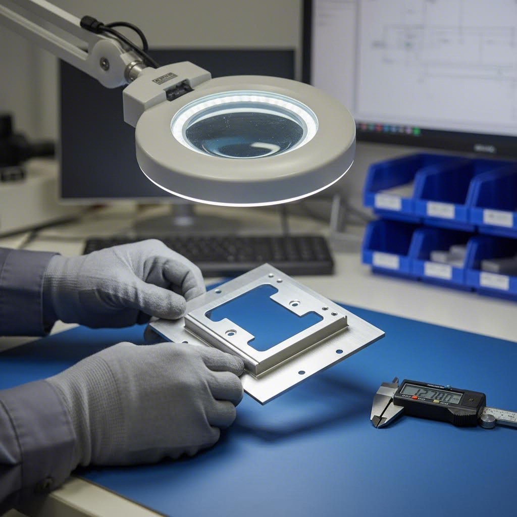
For machined features specifically, implement these quality control checkpoints:
- First article inspection: Measure all critical dimensions on initial parts before production run continues
- In-process gauging: Use go/no-go gauges for threaded holes; verify hole diameters with pin gauges
- Surface finish measurement: Profilometer readings confirm Ra values meet specification
- Dimensional verification: CMM (Coordinate Measuring Machine) inspection for positional accuracy on critical features
- Visual inspection: Check for burrs, tool marks, and surface defects at each production stage
- Thread verification: Thread gauges confirm class fit; torque testing validates functional engagement
Documentation matters too. Maintaining inspection records creates traceability—essential for aerospace, medical, or automotive applications where part history must be verifiable. Random sampling during production catches drift before it creates batch-wide problems.
For hole features, the relationship between your design specification and the drill chart used during manufacturing determines acceptance criteria. Specifying H7 tolerance on a 6mm hole means accepting anything from 6.000mm to 6.012mm—communicate this clearly to avoid disputes over "in-spec" versus "target" dimensions.
Understanding these precision standards and verification methods positions you to design parts that are manufacturable, inspectable, and functional. But achieving tight tolerances starts earlier—at the design stage—where smart decisions prevent problems before they occur.
Design Guidelines and Defect Prevention
You've specified your tolerances and understand inspection methods—but here's what separates smooth production runs from frustrating rework cycles: designing parts that are actually machinable in the first place. Working with sheet metal requires a different mindset than designing for thick-stock CNC operations, and ignoring these constraints leads to rejected parts, blown budgets, and missed deadlines.
Design for manufacturability (DFM) isn't about limiting creativity—it's about understanding what CNC tools and thin materials can realistically achieve. Master these guidelines, and your designs move from CAD to finished parts without the back-and-forth revisions that plague poorly conceived projects.
Design Rules for Machinable Features
Every sheet metal fabrication technique has constraints, and machining operations are no exception. The rules below reflect physical limitations of cutting tools, material behavior, and fixturing realities.
Minimum hole diameters depend directly on sheet thickness. According to DFMPro's sheet metal guidelines, the diameter of any hole should equal or exceed the material thickness. Why? Small holes require small punches or drill bits that break under cutting forces. A 1.5mm hole in 2mm aluminum sheet? That's asking for tool failure and production delays.
Edge distances for holes prevent material deformation during cutting. The same DFMPro guidelines recommend maintaining minimum distances from holes to part edges of at least three times the sheet thickness for standard holes—and six times thickness between adjacent extruded holes. Ignore this, and you'll see tearing, bulging, or complete edge failure.
Here's a practical DFM checklist for machinable sheet metal features:
- Hole diameter: Minimum equals sheet thickness (1:1 ratio)
- Hole-to-edge distance: Minimum 3× sheet thickness for standard holes
- Hole-to-hole spacing: Minimum 2× sheet thickness between centers
- Extruded hole spacing: Minimum 6× sheet thickness between features
- Milled pocket depth: Maximum 60% of sheet thickness (maintain 40% floor)
- Minimum slot width: 1.5× sheet thickness for clean cutting
- Bend-to-feature distance: Minimum 5× thickness plus bend radius from any machined feature
Tool access considerations often get overlooked until machining begins. Tapping operations require clearance for the tap holder and spindle—nearby walls or flanges can physically block tool entry. When designing tapped holes near bends, verify that the fully formed part still allows tool access from the machining direction.
For sheet metal assembly applications, consider how machined features interact with mating components. Countersunk holes require minimum sheet thickness of 2.5mm for stainless steel and 3mm for aluminum—thinner materials deform during countersinking, preventing proper screw seating.
Fixturing Requirements for Thin Materials
Sounds complex? It doesn't have to be—but fixturing thin sheet material demands different approaches than clamping solid blocks.
Traditional edge clamping fails with sheet metal. According to DATRON's machining guide, thin sheets are inherently less rigid, making edge clamping nearly impossible without the sheet lifting or shifting during machining. Cutting forces pull the material upward, causing movement and inaccuracies that ruin tolerances.
Effective fixturing solutions for thin materials include:
- Vacuum tables: Aluminum chucks with vacuum grids hold sheets firmly without mechanical clamps—ideal for nonferrous materials
- Double-sided tape: Prevents center lifting but adds setup time; coolant can degrade adhesive
- Sacrificial sub-plates: Custom fixtures with threaded holes allow through-fastening without damaging parts
- Permeable vacuum systems: Advanced tables use sacrificial cardboard layers, maintaining vacuum even when cutting completely through
Your design can facilitate fixturing by incorporating sacrificial tabs or locating holes that get removed after machining. These fabrication techniques add material during cutting that serves as clamping points, then gets trimmed away during final operations.
Avoiding Common Design Pitfalls
Even experienced designers make these mistakes. Knowing what goes wrong—and why—helps you avoid the defects that turn profitable jobs into costly rework.
Burr formation tops the defect list. According to LYAH Machining's failure analysis, burrs are a common issue in sheet metal parts, especially after cutting, punching, or shearing. These sharp edges create handling hazards and can prevent proper sheet metal joining during assembly.
Preventing burrs starts at design:
- Specify deburring as a required secondary operation
- Use climb milling rather than conventional milling when possible
- Maintain sharp tooling—dull tools push material rather than cutting cleanly
- Design exit paths that minimize unsupported material at cut completion
Warping and distortion plague thin sheet machining when heat concentrates in localized areas. Aggressive cutting generates thermal stress that thin material cannot absorb evenly. The solution? Reduce cutting depths, increase spindle speeds, and ensure adequate coolant reaches the cutting zone. For critical flatness requirements, consider stress-relief operations between roughing and finishing passes.
Tool marks and chatter result from workpiece vibration during cutting—a direct consequence of inadequate fixturing or excessive cutting forces. The inherent flexibility of sheet metal amplifies vibration that would be imperceptible in thick stock. Reducing feed rates and taking lighter cuts often eliminates chatter without sacrificing productivity.
Additional metal fabrication techniques for defect prevention include:
- For hole misalignment: Use pilot holes before final drilling; verify CNC programming coordinates match drawing intent
- For thread stripping: Verify minimum material thickness supports required thread engagement; consider thread-forming rather than thread-cutting taps
- For surface scratches: Apply protective film before machining; specify handling procedures for finished parts
- For dimensional variation: Implement statistical process control; inspect first articles before production runs
The common thread across all these defects? Prevention costs less than correction. Investing time in DFM review before releasing drawings pays dividends in reduced scrap, faster deliveries, and parts that actually work in your assemblies.
With proper design guidelines in place, you're ready to explore where sheet metal machining delivers the greatest value—specific industry applications where precision machined features make the difference between acceptable and exceptional performance.
Industry Applications and Use Cases
Now that you understand design principles and defect prevention, where does sheet metal machining actually deliver the greatest value? The answer spans virtually every industry demanding precision—but certain applications showcase the process's unique strengths better than others.
When parts require both the structural efficiency of formed sheet metal and the precision of machined features, hybrid manufacturing approaches become essential. Let's explore the industries where this combination creates components that simply couldn't exist through fabrication or machining alone.
Automotive and Chassis Applications
The automotive industry represents one of the most demanding environments for sheet metal fabrication and machining. Chassis components, suspension brackets, and structural assemblies must withstand extreme loads while maintaining precise dimensional tolerances across millions of production cycles.
Consider a typical suspension mounting bracket. The basic form comes from stamped or formed steel—efficient material usage creating the structural shape. But the mounting holes? Those require machined precision. Positional accuracy of ±0.05mm ensures proper alignment with suspension components, preventing premature wear and maintaining vehicle handling characteristics.
According to Pinnacle Precision's applications guide, automotive sheet metal parts must meet strict durability standards, with components designed to withstand harsh environments and demanding conditions. This dual requirement—structural strength plus machined precision—defines modern automotive manufacturing.
Steel fabrication for automotive applications demands adherence to rigorous quality standards. The IATF 16949 certification specifically governs automotive manufacturing quality systems, focusing on defect prevention, continuous improvement, and waste reduction. Manufacturers like Shaoyi (Ningbo) Metal Technology demonstrate how IATF 16949-certified processes deliver the consistency required for chassis, suspension, and structural components across high-volume production runs.
Key requirements for automotive sheet metal machining include:
- Dimensional consistency: Tight tolerances maintained across production volumes exceeding 100,000 units annually
- Material traceability: Complete documentation from raw material through finished part
- Surface protection: Corrosion resistance through appropriate coatings—zinc plating, e-coating, or powder coating services
- Weight optimization: Balancing structural requirements against vehicle efficiency targets
- Rapid prototyping capability: 5-day turnaround for development samples enables accelerated vehicle programs
The hybrid approach proves particularly valuable here. A typical chassis component might undergo laser cutting for perimeter profiles, stamping for formed features, and CNC machining for precision mounting holes—all coordinated through integrated manufacturing workflows that maintain datum references between operations.
Aerospace Bracket Manufacturing
If automotive demands precision, aerospace demands perfection. The aerospace industry relies on sheet metal machining for brackets, structural supports, and intricate assemblies where failure simply isn't an option.
According to Pinnacle Precision, aerospace precision sheet metal parts must meet strict quality and safety standards to ensure reliability in challenging environments. Components face extreme temperature cycling, vibration loading, and corrosive atmospheres—all while maintaining dimensional stability.
Anodized aluminum dominates aerospace sheet metal applications for good reason. The anodizing process creates a hard, corrosion-resistant oxide layer that protects lightweight aluminum structures throughout decades of service. When these anodized components require threaded mounting points or precision-located holes, machining operations add functional features without compromising the protective surface treatment.
Aerospace-specific requirements extend beyond dimensional accuracy:
- AS9100D certification: Quality management systems specific to aerospace manufacturing
- Material certification: Full chemical and mechanical property documentation for every material lot
- Non-destructive testing: X-ray, ultrasonic, and dye penetrant inspection for critical components
- Surface finish specifications: Ra values often below 1.6 μm for fatigue-critical applications
- ITAR compliance: Defense-related components require additional security protocols
The metal fab shops serving aerospace customers maintain capabilities that general fabrication shops simply cannot match. According to TMCO's industry analysis, machining takes the lead when precision and complexity are top priorities—exactly the conditions aerospace applications present.
Electronics Enclosure Manufacturing
Walk into any data center, telecommunications facility, or industrial control room, and you'll find electronics enclosures everywhere. These humble boxes protect sensitive equipment from environmental contamination, electromagnetic interference, and physical damage—but creating them demands sophisticated manufacturing coordination.
A typical enclosure starts as flat sheet metal—aluminum for lightweight applications, stainless steel for harsh environments, or cold-rolled steel for cost-sensitive projects. The sheet metal fabrication process creates the basic box: laser-cut blanks, press-brake formed corners, and welded seams producing the structural shell.
But enclosures require more than empty boxes. Circuit boards need precisely located standoffs. Cable glands require threaded holes at exact positions. Card guides demand milled channels with tight dimensional tolerances. This is where machining transforms a simple enclosure into a functional electronic housing.
According to Pinnacle Precision's applications overview, the electronics industry relies on precision sheet metal parts for casings, brackets, and intricate components that protect sensitive electronics from environmental factors and electromagnetic interference.
Electronics enclosure requirements typically include:
- EMI/RFI shielding effectiveness: Continuous electrical contact across all panel joints
- Thermal management: Machined ventilation patterns or heat sink mounting provisions
- IP rating compliance: Ingress protection requiring gasketed interfaces at precise tolerances
- Cosmetic finish quality: Powder coating services or anodized aluminum for customer-facing equipment
- Modular design: Standardized mounting patterns for interchangeable internal components
The hybrid manufacturing approach proves essential for electronics enclosures. Fabrication creates the structure efficiently; machining adds the precision features that make the enclosure functional. Metal fabricators near me searches often reveal shops offering both capabilities—but verifying their precision machining tolerances before committing matters significantly.
Precision Assemblies and Hybrid Manufacturing
Perhaps the most compelling applications for sheet metal machining involve complex assemblies where multiple formed and machined components must work together with zero tolerance for misalignment.
Imagine a medical device housing requiring:
- Formed sheet metal structure for electromagnetic shielding
- Machined mounting bosses for internal component location
- Threaded inserts for serviceable access panels
- Precision-located sensor mounting holes
- Welded internal brackets requiring post-weld machining
No single manufacturing process handles all these requirements efficiently. The solution? Coordinated hybrid manufacturing where each operation builds upon previous steps while maintaining critical datum references throughout.
According to TMCO's manufacturing integration guide, combining fabrication and machining leverages the strengths of both methods—fabrication's scalability and cost efficiency paired with machining's precision and complexity capability. This integrated approach reduces lead times, ensures tighter quality control, and streamlines production workflows.
Aluminum welding presents particular challenges for hybrid assemblies. The heat-affected zone from welding can distort precision features machined before assembly. Experienced fabrication shops near me solve this by sequencing operations strategically—machining critical features after welding and stress relief, maintaining dimensional accuracy despite thermal processing.
Quality certifications matter significantly for precision assemblies. ISO 9001 provides the foundation, with industry-specific standards adding specialized requirements. According to Kaierwo's quality standards analysis, over 1.2 million companies worldwide hold ISO 9001 certification, establishing baseline quality management for fabrication operations. For automotive applications specifically, IATF 16949 builds upon ISO 9001 with enhanced requirements for defect prevention and continuous improvement.
The sheet metal processing workflow for precision assemblies typically follows this sequence:
- Material preparation: Incoming inspection, cutting to rough size
- Primary fabrication: Laser cutting, forming, welding primary structure
- Heat treatment: Stress relief if required for dimensional stability
- Machining operations: Drilling, tapping, milling precision features
- Surface treatment: Cleaning, coating, finishing
- Final assembly: Component integration, functional testing
- Inspection: Dimensional verification, documentation
Throughout this sequence, maintaining datum references between operations ensures that machined features align correctly with fabricated geometry—the critical success factor separating functional assemblies from expensive scrap.
Understanding where sheet metal machining delivers value helps you identify opportunities in your own applications. But translating those opportunities into actual projects requires understanding the cost factors involved—what drives pricing, how to optimize designs for economy, and what manufacturers need to provide accurate quotes.
Cost Factors and Project Optimization
You've designed a manufacturable part, selected the right material, and identified where sheet metal machining adds value—but what will it actually cost? This question frustrates engineers and procurement specialists alike because pricing in sheet metal manufacturing depends on interconnected variables that aren't always obvious.
Understanding what drives costs empowers you to make design decisions that optimize both performance and budget. Let's decode the pricing factors that determine whether your project comes in under budget or blows through estimates.
Key Cost Drivers in Sheet Metal Machining
Every quote you receive reflects a complex calculation weighing material, labor, tooling, and overhead. Knowing which factors carry the most weight helps you prioritize optimization efforts where they'll have the greatest impact.
Material type and thickness form the foundation of any estimate. According to Komacut's cost guide, different metals present unique cost characteristics—aluminum's lightweight nature suits weight-critical applications but carries higher per-kilogram costs than mild steel. Stainless steel commands premium pricing due to both material cost and increased machining difficulty.
Thickness impacts cost in two directions. Thicker materials cost more per square meter but often machine more efficiently due to improved rigidity. Thin sheets require specialized fixturing—vacuum tables, sacrificial backing, careful clamping—that adds setup time and labor cost.
Machining complexity directly correlates with cycle time and tooling requirements. A simple drilling pattern completes in minutes; a part requiring milled pockets, multiple tapped hole sizes, and countersunk recesses demands extended machine time and multiple tool changes. Each additional operation adds cost, though the incremental expense decreases when operations can be completed in a single setup.
Tolerance requirements represent one of the most significant—and often overlooked—cost multipliers. According to okdor's DFM guide, tightening tolerances from standard ±0.030" to ±0.005" on non-critical dimensions increased one project's cost by 25% with no functional benefit. Steel fabricators must slow cutting speeds, add inspection steps, and sometimes implement climate-controlled machining for tight-tolerance work.
| Cost Factor | Low Impact | Medium Impact | High Impact |
|---|---|---|---|
| Material Selection | Mild steel, standard gauges | Aluminum alloys, stainless 304 | 316 stainless, specialty alloys |
| Thickness Range | 1.5mm – 4mm (optimal rigidity) | 0.8mm – 1.5mm or 4mm – 6mm | Below 0.8mm (fixturing challenges) |
| Feature Count | 1-5 simple holes per part | 6-15 mixed features | 15+ features with tight spacing |
| Tolerance Class | Standard ±0.1mm | Precision ±0.05mm | High-precision ±0.025mm |
| Production Volume | 100-500 parts (optimal efficiency) | 10-100 or 500-2000 parts | 1-10 parts (setup cost dominant) |
| Secondary Operations | None required | Deburring, basic finishing | Multiple coatings, assembly |
Volume considerations create non-linear pricing curves. Single prototypes carry high per-part costs because setup time gets divided across one unit. As quantities increase, setup amortizes across more parts—but at very high volumes, sheet metal processing may shift to stamping or progressive die operations that require tooling investment.
Secondary operations add cost layers beyond primary machining. Surface finishing, heat treatment, coating application, and assembly labor each contribute to final pricing. What is sheet metal fabrication cost without finishing? Often incomplete—bare machined parts rarely ship directly to end-use applications.
Optimizing Projects for Cost Efficiency
Smart optimization starts during design, not after quotes arrive. The decisions you make in CAD directly determine what manufacturers can offer on pricing.
Tolerance optimization delivers the quickest wins. According to okdor's DFM recommendations, identifying your 3-5 most critical assembly interfaces and tolerancing only those features—while leaving everything else at standard specifications—reduces manufacturing cost without compromising function. Position callouts for hole patterns often work better than tight coordinate dimensions, giving fabricators flexibility while controlling what actually matters.
Design consolidation reduces part count and assembly labor. However, the sheet metal process sometimes favors splitting complex parts into simpler pieces. According to the same DFM guide, complex parts with 4+ bends or tight feature spacing often cost more than designing separate pieces joined with fasteners. The decision framework depends on volume: below 100 units, split designs usually win; above 500 units, welded assemblies eliminate fastener costs.
Material standardization improves lead times and reduces material cost. Specifying common gauges and readily available alloys avoids minimum-order charges and extended procurement timelines. When searching for metal fabrication near me, shops with material inventory can often start production faster than those ordering specialty stock.
Working with manufacturers who offer comprehensive DFM support accelerates optimization. Experienced partners like Shaoyi (Ningbo) Metal Technology provide design feedback before production commitment, identifying cost-reduction opportunities that aren't obvious from CAD geometry alone. Their 12-hour quote turnaround enables rapid iteration—submit a design, receive feedback, refine, and resubmit within a single business day.
Getting Accurate Quotes Faster
What information do manufacturers actually need to provide reliable estimates? Incomplete submissions create delays and inaccurate pricing that wastes everyone's time.
For accurate sheet metal manufacturing quotes, prepare:
- Complete CAD files: STEP or native format preferred; 2D drawings for tolerance callouts
- Material specification: Alloy, temper, and thickness—not just "aluminum"
- Quantity requirements: Initial order plus anticipated annual volume
- Tolerance specifications: GD&T callouts for critical features; general tolerances stated
- Surface finish requirements: Ra values for machined surfaces; coating specifications if applicable
- Secondary operations: Heat treatment, finishing, assembly, testing requirements
- Delivery timeline: Required delivery date and any phased release schedules
Quote turnaround varies significantly across the industry. Some shops require weeks; others leverage automated systems for rapid response. When evaluating suppliers, rapid quoting capability often indicates streamlined operations that translate to reliable production performance.
The most cost-effective projects result from collaborative relationships where manufacturers contribute expertise during design development rather than simply pricing completed drawings. DFM support transforms the quoting process from transactional to consultative—identifying issues before they become production problems and optimizing designs for both function and economy.
Frequently Asked Questions About Sheet Metal Machining
1. What are common sheet metal cutting mistakes?
Common sheet metal cutting mistakes include inadequate cutting parameters that cause poor edge quality, tool wear from lack of maintenance leading to burrs and inaccuracies, improper sheet alignment and clamping causing dimensional errors, and ignoring material conditions like work hardening in stainless steel. Preventing these issues requires proper fixturing with vacuum tables or sacrificial backing, maintaining sharp tooling, verifying CNC programming coordinates, and adjusting feeds and speeds based on material type. Working with IATF 16949-certified manufacturers like Shaoyi ensures quality systems that catch these issues before they become production problems.
2. What is the difference between sheet metal machining and fabrication?
Sheet metal machining refers specifically to CNC-controlled subtractive operations like milling, drilling, tapping, and countersinking that remove material to create precise features. Fabrication involves shaping sheet material through cutting, bending, and joining operations without necessarily removing material. While fabrication shapes the overall form through laser cutting, press brake bending, and welding, machining refines that form by adding precision features such as threaded holes, milled pockets, or countersunk recesses that fabrication cannot produce. Most real-world projects combine both processes for optimal results.
3. What tolerances can sheet metal machining achieve?
Sheet metal machining achieves tight tolerances depending on the operation type. CNC milling delivers the tightest precision at ±0.025mm for positional accuracy and feature dimensions. Drilling operations typically hold ±0.05mm for hole diameter and position. Tapping follows thread class specifications, with most applications using 6H/6G classes for medium fit. However, material tolerances stack with machining tolerances—aluminum sheets carry thickness tolerances of ±0.06mm while stainless steel holds ±0.040-0.050mm. Critical features may require first article inspection and CMM verification.
4. Which materials work best for sheet metal machining?
Aluminum alloys like 6061 and 5052 offer the best machinability with high thermal conductivity, allowing faster cutting speeds and longer tool life. Stainless steel grades, particularly 316, present challenges due to work hardening and poor thermal conductivity, requiring slower speeds and more frequent tool changes. Mild steel provides a balanced middle ground with good machinability and moderate tool wear. Material selection affects tolerances, surface quality, and costs—aluminum costs less to machine despite higher material prices, while stainless steel commands premium pricing for both material and processing.
5. How can I reduce sheet metal machining costs?
Optimize costs by tolerancing only critical features while leaving non-critical dimensions at standard specifications—tightening tolerances unnecessarily can increase costs by 25% or more. Standardize materials using common gauges and readily available alloys to avoid minimum-order charges. Consider hybrid manufacturing approaches combining laser cutting for profiles with machining for precision features. Work with manufacturers offering DFM support like Shaoyi, whose 12-hour quote turnaround and comprehensive design feedback identify cost-reduction opportunities before production. For volumes above 500 units, consider whether split designs or welded assemblies offer better economics.