 Small batches, high standards. Our rapid prototyping service makes validation faster and easier —

Sheet Metal Forming Products: Pick The Right Method Every Time
What Are Sheet Metal Forming Products and Why They Matter
Ever wondered how a flat piece of metal becomes the smartphone case in your pocket or the aircraft panel soaring overhead? The answer lies in sheet metal forming—a manufacturing process that transforms thin metal sheets into precise, three-dimensional components without removing any material. These sheet metal forming products surround us daily, from beverage cans and household appliances to critical aerospace structures and automotive body panels.
From Flat Sheets to Functional Parts
At its core, sheet metal forming involves reshaping thin metal sheets using controlled force and deformation. Think of it like origami, but with metal—you're bending, stretching, and pressing flat material into complex shapes while maintaining structural integrity. The typical thickness ranges from 0.5 mm to 6 mm, making this process ideal for producing brackets, panels, housings, and enclosures.
What makes this process remarkable? The metal retains its strength throughout the transformation. Whether you're working with stainless steel, aluminum, titanium, or copper, the material's properties remain intact while taking on entirely new forms. This means manufacturers can create strong, dimensionally stable components in high volumes with minimal waste.
The Science Behind Metal Transformation
Here's where forming fundamentally differs from other manufacturing methods. Unlike machining—which cuts, drills, and grinds material away—forming reshapes metal through controlled deformation. Imagine the difference between sculpting clay by adding and shaping versus carving stone by removing pieces. Metal shaping tools and metal shaping equipment apply precise pressure to bend, stretch, or compress sheets into desired configurations.
This distinction matters for several practical reasons:
- Material efficiency: No material is wasted during the forming process
- Structural integrity: The metal's grain structure remains continuous, enhancing strength
- Cost-effectiveness: Fewer raw materials needed compared to subtractive methods
- Speed: Formed parts often require minimal secondary operations
The science relies on understanding how different metals behave under stress. Ductility, yield strength, and work hardening characteristics all influence how effectively a material can be formed—and which sheet metal forming tools work best for each application.
Why Forming Beats Fabrication for Many Applications
When comparing forming to other fabrication methods, the advantages become clear. According to Xometry's manufacturing resources, sheet metal forming offers exceptional versatility at relatively low cost, producing parts with outstanding strength-to-weight ratios. Industries from aerospace to medical devices rely on metal forming tools because they deliver consistency, speed, and precision that alternative methods struggle to match.
Consider the scope of products created through these processes:
- Simple components like mounting brackets and electrical enclosures
- Complex curved surfaces found in automotive body panels
- Seamless hollow structures like medical device housings
- Aerodynamic aerospace fuselage panels meeting the tightest tolerances
This guide will walk you through everything you need to understand about forming tools and processes—from the fundamental techniques and essential equipment to material selection and quality control. You'll learn how to match specific forming methods to your project requirements, whether you're producing simple bent components or complex deep-drawn assemblies. By the end, you'll have the knowledge to select the right approach for your manufacturing needs every time.
Core Sheet Metal Forming Processes and Their Products
Now that you understand what sheet metal forming products are, let's explore how they're actually made. Each forming process creates distinct product types—and understanding these process-to-product relationships helps you select the right method for your specific application. Whether you need angular brackets or seamless cylindrical containers, there's a forming technique designed for that exact purpose.
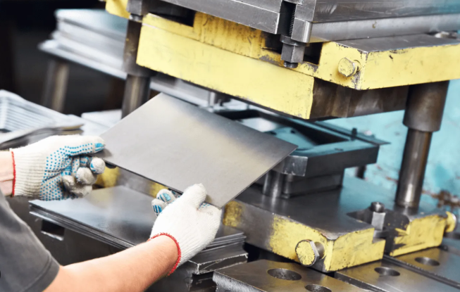
Stamping and Press Operations Explained
Stamping ranks among the most versatile and widely used metal forming processes in manufacturing. The concept is straightforward: a press machine forces a punch through sheet metal positioned over a die, creating precisely shaped components in a single stroke or series of progressive operations.
Imagine pressing a cookie cutter through dough—stamping works similarly, but with tremendous force applied to metal sheets. According to Prospect Machine Products, metal forming is achieved through plastic deformation, applying force greater than the material's yield strength to permanently reshape it.
Key characteristics of stamping operations include:
- High-volume capability: Produces thousands of identical parts per hour
- Excellent repeatability: Tool-controlled processes ensure dimensional consistency
- Multiple operations: Blanking, piercing, embossing, and forming can occur in sequence
- Material versatility: Works with steel, aluminum, brass, and specialty alloys
Typical stamped products include automotive brackets, electronic enclosures, appliance panels, and hardware components. The press machine—whether mechanical or hydraulic—delivers the force needed to shape metal against precision-engineered dies.
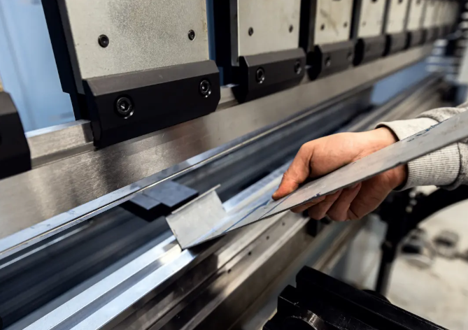
Bending and Brake Forming Fundamentals
When your project requires angular components with defined bends, a press brake becomes your primary forming tool. This sheet metal brake positions material on a die while a punch descends to create precise angles—from simple 90-degree bends to complex multi-bend profiles.
What makes bending so popular? As Precision Stamping Inc. explains, bending offers manufacturers significant versatility and efficiency with minimal tooling requirements. This allows quick adjustments to designs, making it ideal for prototypes and small production runs.
A sheet metal bender or metal bender creates products like:
- Mounting brackets and structural supports
- Electrical enclosure frames and covers
- Machine guards and protective housings
- Furniture components and shelving systems
- HVAC ductwork and architectural elements
The press brake machine comes in various configurations—from manual bench-mounted units for small workshops to CNC-controlled hydraulic systems producing complex multi-bend parts with exceptional precision. Related equipment like tube benders, pipe benders, and tubing benders apply similar principles to round stock, creating curved frames, handrails, and structural components.
Deep Drawing for Complex Shapes
Need seamless hollow containers without joints or welds? Deep drawing transforms flat metal blanks into three-dimensional shapes by pressing material through a die cavity. This process produces cups, cylinders, enclosures, and complex curved surfaces that would be impossible or impractical to achieve through bending alone.
Here's how it works: a metal blank sits over a specialized die, and a punch forces it downward into the cavity. The material stretches and flows around the punch, taking its shape. According to Amalco's Professor Metal, approximately 40% of the blank diameter can be drawn in a single operation—meaning a 10-inch diameter blank can be drawn to 6 inches, resulting in a height of about 2¾ inches.
Deep drawing characteristics include:
- Seamless construction: No joints, welds, or fasteners required
- Uniform wall thickness: Material distributes evenly during forming
- Structural integrity: Parts withstand pressure and stress without failure points
- Economical for volume: Minimal material waste and rapid production cycles
Common deep-drawn products include automotive fuel tanks, kitchen sinks, cookware, beverage cans, medical device housings, and aerospace components. The process excels when parts must be liquid-tight, pressure-resistant, or require smooth interior surfaces.
Specialized Techniques Including Hydroforming
Beyond conventional stamping and drawing, specialized techniques expand what's possible with sheet metal forming products. Hydroforming uses fluid pressure instead of mechanical force to shape metal around a punch—creating complex geometries with exceptional surface quality.
As Amalco describes, hydroforming utilizes a punch, a ring, a pressurized forming chamber, and a flexible rubber diaphragm. The metal blank is placed over the punch, the chamber closes, and fluid pressure forces the material to conform precisely to the tooling shape.
Roll forming takes a different approach entirely. Instead of pressing material in a single operation, sheet metal passes through a series of roller dies that progressively shape it into continuous profiles. This process creates:
- Structural channels and angles
- Roofing and siding panels
- Automotive trim and moldings
- Shelving tracks and rails
Each specialized technique serves specific product categories. Hydroforming excels at complex compound curves with tight tolerances, while roll forming dominates when you need long, consistent profiles at high production speeds. Understanding which process creates which products helps you make informed decisions about manufacturing approaches—a topic we'll explore further as we examine the equipment that makes these operations possible.
Essential Equipment for Sheet Metal Forming Operations
Understanding forming processes is one thing—having the right equipment to execute them is another entirely. Whether you're crafting custom motorcycle tanks in a home garage or producing thousands of automotive panels daily, your equipment determines what's possible. Let's explore the complete spectrum of sheet metal forming tools, from precision hand implements to industrial automated systems.
Hand Tools for Precision Forming Work
Every metal fabricator starts somewhere, and sheet metal hand tools remain essential even in advanced shops. These implements offer control, precision, and versatility that machines simply cannot replicate for certain applications.
Consider the fundamental toolkit for manual forming work:
- Aviation snips: Left-cut, right-cut, and straight varieties for precise trimming
- Seamers and folders: Create clean bends and lock seams by hand
- Dollies and hammers: Shape compound curves through controlled striking
- Stakes and mandrels: Support material while forming curves and edges
- Measuring and marking tools: Scribes, dividers, and gauges ensure accuracy
Hand tools shine when you need to finesse a complex curve, repair damaged panels, or create one-off artistic pieces. The planishing hammer—whether hand-held or powered—smooths surfaces and work-hardens metal after initial shaping. Skilled craftspeople can achieve remarkable results with nothing more than hammers, dollies, and decades of practice.
For cutting operations before forming begins, a metal bandsaw provides clean, accurate cuts through various gauges. Depending on your shop layout and material handling needs, you might choose between a horizontal band saw for straight cuts through bar stock or a vertical band saw for following curves and intricate patterns in sheet material.
Bench Equipment for Workshop Production
Step up from hand tools, and you'll find bench-mounted equipment that bridges the gap between manual craftsmanship and industrial production. This category serves hobbyists, custom fabricators, and prototype shops exceptionally well.
The bead roller deserves special attention here. According to demonstrations from Baileigh Industrial's metal shaping seminars, artisans use bead rollers outfitted with step and art dies to produce beautiful decorative panels and structural reinforcements. The bead roller creates raised lines, stepped edges, and artistic patterns that both strengthen panels and add visual interest.
The english wheel represents another cornerstone of workshop metal shaping. This deceptively simple machine—consisting of a large flat wheel above and an interchangeable anvil wheel below—creates smooth compound curves through repeated passes. Automotive restoration specialists and aircraft builders rely on english wheels to form fender flares, body panels, and fuselage sections.
Other essential bench equipment includes:
- Bench brakes: Secure positioning for consistent bends on mid-size panels
- Shrinker/stretchers: Adjust edge lengths to create curves and flanges
- Rotary machines: Form beads, flanges, and crimps in circular motions
- Slip rolls: Create cylinders and cones from flat sheets
As noted in Penn Tool Co.'s equipment guide, bench brakes offer more control than hand brakes but less complexity than press brakes—finding their niche for workshops handling mid-size panels regularly.
Industrial Machinery for Volume Manufacturing
When production demands increase, industrial machinery delivers the force, speed, and repeatability that bench equipment cannot match. These systems represent significant investments but enable high-volume output with consistent quality.
The power hammer transforms metal shaping capabilities dramatically. Master coach builders, like Ferrari restorers, use power hammers exclusively to create complex automotive body panels. The power hammer applies controlled, rapid strikes that stretch, shrink, and smooth metal far faster than manual hammering—while the operator guides the material to achieve precise contours.
Industrial forming equipment categories include:
- Hydraulic and CNC press brakes: Programmable bending with tonnage capacities from 40 to 1,000+ tons
- Power roll forming machines: Continuous production of consistent profiles
- Turret and CNC punch presses: High-speed hole creation and blanking operations
- Shearing machines: Straight-line cuts through heavy gauge materials
Equipment selection at this level depends heavily on production requirements. According to Penn Tool Co., factors like material thickness, required precision, and desired automation levels all influence which machinery best serves your operation.
| Equipment Category | Typical Applications | Capacity Range | Products Created |
|---|---|---|---|
| Sheet Metal Hand Tools | Custom work, repairs, artistic pieces | Up to 18 gauge steel | Patches, small panels, decorative elements |
| Bead Roller | Panel reinforcement, decorative work | 18-22 gauge typical | Beaded panels, stepped edges, artistic designs |
| English Wheel | Compound curves, body panels | Up to 16 gauge aluminum | Fenders, hoods, aircraft skins |
| Planishing Hammer | Surface finishing, work hardening | 18-22 gauge typical | Smoothed panels, bowls, sculptural forms |
| Power Hammer | Production shaping, heavy forming | Up to 14 gauge steel | Automotive panels, domes, complex curves |
| Bench Brake | Consistent bends, medium production | Up to 16 gauge, 24-48" width | Brackets, boxes, enclosure components |
| CNC Press Brake | High-volume precision bending | Up to 1/2" steel, 10'+ length | Structural components, complex profiles |
| Roll Forming Machine | Continuous profile production | Varies by configuration | Channels, tracks, roofing panels |
The relationship between equipment and output is direct: folders create creased bends, shears produce straight cuts, brakes form angular components, and roll benders generate curved profiles. Matching your equipment to your intended products—rather than adapting products to available equipment—yields better results and greater efficiency.
With the right tools in place, the next critical decision involves selecting appropriate materials. Different metals behave uniquely during forming, and understanding these characteristics prevents costly mistakes while optimizing your finished products.
Material Selection Guide for Forming Applications
You've got the right equipment lined up—but here's where many projects go wrong. Choosing the wrong material for your forming application leads to cracked parts, excessive springback, or components that fail under load. Understanding how different metals behave during forming transforms guesswork into confident decision-making. Let's explore what makes each material unique and how to match your selection to specific forming requirements.
Understanding Metal Formability Characteristics
What determines whether a metal forms beautifully or fractures under pressure? Three critical properties drive formability: ductility, yield strength, and work hardening behavior.
Ductility measures a material's ability to deform plastically without breaking. According to Meviy USA's engineering resources, ductile materials like copper, aluminum, and mild steel undergo significant deformation without failing—while brittle materials like cast iron fracture suddenly with little warning. In forming operations, high ductility means you can stretch, bend, and draw metal into complex shapes without cracking.
Here's how key forming properties affect your material choice:
- Ductility: Determines how much stretching and bending the material tolerates before failure
- Yield strength: The stress level where permanent deformation begins—lower values mean easier forming but reduced structural capacity
- Work hardening rate: How quickly material becomes stronger (and less formable) during deformation
- Elastic recovery: The amount of springback after forming pressure releases
- Anisotropy: Directional differences in material properties affecting forming behavior
Materials with excellent ductility provide warning signs before failure—they bend, stretch, and deform visibly. This behavior matters tremendously in forming operations where you're pushing material to its limits. As noted in material science research, ductility is typically measured through percent elongation and reduction of area tests, helping manufacturers predict how metals will perform during stamping, drawing, and bending.
Matching Materials to Forming Methods
Each metal brings distinct characteristics to forming operations. Understanding these differences helps you select appropriate processes and anticipate potential challenges.
Aluminum ranks among the most formable metals available. Its excellent ductility and low yield strength make it ideal for deep drawing, complex stamping, and aerospace applications where weight reduction matters. However, aluminum work-hardens relatively quickly, so multi-stage forming operations may require intermediate annealing.
Mild steel offers the workhorse balance of formability, strength, and cost-effectiveness. It bends cleanly, stamps reliably, and deep draws effectively—making it dominant in automotive and industrial applications. Carbon content directly affects formability: low-carbon steels form easily while higher-carbon grades resist deformation.
Stainless steel presents greater challenges. Higher yield strength means you need more forming force, while rapid work hardening limits how much deformation occurs before the material becomes too hard to shape further. Different kinds of welding may also affect heat-affected zones that change local formability. Grades 304 and 316 are common choices, with 304 offering better formability for drawn components.
Copper and brass exhibit exceptional ductility, allowing intricate forming and detailed embossing. These materials flow smoothly during deep drawing and tolerate tight bend radii without cracking. Their softness, however, means they dent and scratch easily during handling.
Specialty alloys including titanium, Inconel, and high-strength aluminum alloys require specialized knowledge. Titanium's springback behavior demands significant overbending compensation, while nickel-based superalloys may need hot forming to achieve desired shapes.
Gauge Selection for Optimal Results
Metal gauge thickness directly impacts which forming methods work effectively and how finished products perform. Understanding sheet metal gauges—and interpreting steel gauge and thickness specifications—prevents costly mismatches between material and process.
Here's the practical reality: thicker materials require more force, larger bend radii, and more powerful equipment. A metal thickness gauge helps verify incoming material meets specifications, but understanding the relationship between gauge numbers and actual dimensions matters more.
| Metal Gauge Thickness | Steel Thickness (inches) | Aluminum Thickness (inches) | Typical Forming Applications |
|---|---|---|---|
| 24 gauge | 0.024" | 0.020" | HVAC ductwork, light enclosures, decorative panels |
| 20 gauge | 0.036" | 0.032" | Automotive panels, appliance housings, electrical boxes |
| 18 gauge | 0.048" | 0.040" | Structural brackets, machine guards, heavy enclosures |
| 16 gauge | 0.060" | 0.051" | Industrial equipment, automotive structural components |
| 14 gauge | 0.075" | 0.064" | Heavy machinery, structural frames, reinforced panels |
Notice something important: sheet metal gauge numbers don't represent the same thickness across different metals. A 20-gauge steel sheet measures differently than 20-gauge aluminum. Always verify actual thickness specifications rather than assuming gauge numbers translate directly.
For deep drawing operations, thinner gauges generally perform better—they stretch and flow more easily without excessive force requirements. Bending operations tolerate thicker materials more readily, though minimum bend radius increases proportionally with thickness. Stamping capabilities depend heavily on press tonnage and die design relative to material thickness.
The relationship between material choice and industry applications becomes clearer once you understand these fundamentals. Automotive manufacturers select materials balancing crash performance, weight, and forming complexity. Aerospace engineers prioritize strength-to-weight ratios while ensuring materials tolerate their specific forming processes. General manufacturing operations often optimize for cost and availability while meeting minimum performance requirements.
With material selection principles established, you're ready to explore how different industries apply these concepts to their unique requirements—and why certain sectors demand specific material and forming combinations.
Industry Applications for Formed Metal Components
Ever wonder why your car door fits perfectly every single time, or how aircraft panels withstand extreme conditions at 35,000 feet? Different industries don't just use sheet metal forming products—they demand entirely different performance characteristics, tolerances, and production approaches. Understanding these sector-specific requirements helps you appreciate why the same forming processes yield such dramatically different outcomes depending on the application.
Automotive Chassis and Body Component Production
The automotive industry represents the largest consumer of sheet metal forming products globally—and for good reason. Modern vehicles contain hundreds of stamped and formed components, from visible body panels to hidden structural reinforcements.
According to Alsette's automotive manufacturing analysis, stamping is vital because it allows high-speed, low-cost production of strong, lightweight, and very consistent metal parts. Modern stamping presses produce hundreds or even thousands of parts per hour—a pace necessary to keep up with assembly line demands.
What makes automotive forming unique? Consider these requirements:
- Volume demands: Production runs often exceed millions of identical parts annually
- Tight tolerances: Doors, hoods, and fenders must align perfectly across every vehicle
- Class A surfaces: Exterior panels require flawless finishes visible to consumers
- Crash performance: Structural components must meet stringent safety regulations
- Weight optimization: Lighter vehicles improve fuel efficiency and EV range
Automotive stamping encompasses two primary categories. Body panels—including doors, hoods, fenders, roofs, and trunk lids—form the visible exterior requiring perfect surface quality. Structural components—the body-in-white skeleton including A, B, and C pillars, floor pans, and frame rails—prioritize crash performance using high-strength steels.
The precision required means tooling investment runs substantial. A single automotive stamping die can cost hundreds of thousands of dollars, but the per-part cost becomes remarkably low at volume. When fabricators join these formed components, various types of welding and plasma cutting operations complete the assembly process. Welders wearing an auto darkening welding helmet work alongside robotic systems to ensure consistent joint quality across production runs.
Aerospace Structural Forming Requirements
If automotive demands tight tolerances, aerospace requirements border on obsessive. Every gram matters when you're fighting gravity, and every component must perform flawlessly under extreme conditions.
As Teamwork Prototype's aerospace research explains, aerospace engineering is inherently constrained by the weight equation. Every component contributes to overall aircraft weight, directly impacting fuel consumption and operational costs. This drives relentless pursuit of lightweighting through advanced sheet metal solutions.
Aerospace forming differs from automotive in several critical ways:
- Material selection: High-strength aluminum alloys, titanium, and specialty steel alloys dominate
- Production volumes: Lower quantities but extreme precision requirements
- Forming techniques: Deep drawing, hydroforming, and incremental forming create complex geometries
- Quality documentation: Every part requires complete traceability and certification
- Dimensional accuracy: Tolerances measured in thousandths of an inch are standard
The forming processes used reflect these demands. Hydroforming excels at creating complex compound curves with exceptional surface quality—essential for aerodynamic fuselage sections. Deep drawing produces seamless fuel tanks and pressure vessels that must withstand repeated pressurization cycles. Incremental forming enables small-batch production of specialized components without dedicated tooling investment.
Types of welders used in aerospace differ substantially from automotive applications. Electron beam and laser welding join thin-gauge titanium and aluminum alloys with minimal heat-affected zones, preserving material properties. Operators using a welding helmet auto darkening to protect their vision work on components where a single defect could ground an aircraft.
Industrial and Power Generation Applications
Beyond transportation, sheet metal forming products power the infrastructure keeping modern society running. Power generation equipment—from traditional plants to renewable energy systems—relies heavily on precision-formed metal components.
According to Metal Works, Inc.'s industry analysis, renewable energy is the fastest-growing energy source in the United States, skyrocketing 42 percent from 2010 to 2020. This growth drives increasing demand for specialized formed components.
Power generation applications include:
- Solar energy: Panels, frames, mounting posts, and brackets require corrosion-resistant formed components
- Wind turbines: Specialized parts support gearboxes, generators, and blade assemblies
- Hydroelectric: Turbine housings, generator enclosures, and transmission infrastructure rely on heavy-gauge formed steel
- Traditional power plants: Heat exchangers, ductwork, and structural supports demand durability under extreme conditions
Defense and industrial sectors share similar priorities: durability trumps weight optimization, and components must withstand harsh environments for decades. Formed enclosures protect sensitive electronics from environmental exposure. Structural brackets support heavy equipment through vibration and thermal cycling. Heat shields and protective housings maintain safe operating conditions.
What distinguishes industrial forming from consumer-facing applications? The emphasis shifts from visual perfection to functional performance. Surface finish matters less than material thickness, corrosion resistance, and structural integrity. Production volumes vary widely—from custom one-off fabrications to medium-volume standardized components.
| Industry Sector | Primary Forming Methods | Key Quality Metrics | Typical Materials |
|---|---|---|---|
| Automotive | High-speed stamping, progressive die operations | Surface finish, dimensional consistency, crash performance | Mild steel, high-strength steel, aluminum |
| Aerospace | Hydroforming, deep drawing, incremental forming | Weight-to-strength ratio, fatigue resistance, traceability | Aluminum alloys, titanium, specialty steels |
| Power Generation | Heavy-gauge forming, roll forming, deep drawing | Durability, corrosion resistance, longevity | Stainless steel, galvanized steel, aluminum |
| Defense | Specialized forming, armor-grade processing | Ballistic performance, environmental resistance | Armor steel, titanium, specialty alloys |
Understanding how different industries prioritize quality metrics and forming techniques illuminates why material and process selection matters so much. What works brilliantly for automotive body panels may prove entirely unsuitable for aerospace structural components—even when starting with similar sheet metal. The forming method, tooling design, and quality requirements must align with end-use demands.
With industry requirements established, the next critical challenge emerges: ensuring your formed components meet specifications consistently. Quality control and defect prevention strategies separate acceptable results from exceptional manufacturing performance.
Quality Control and Defect Prevention Strategies
You've selected the right material, chosen an appropriate forming method, and invested in quality equipment—but what happens when parts come off the line with unexpected issues? Defects in sheet metal forming products cost manufacturers time, materials, and reputation. Understanding what causes these problems—and how to prevent them—separates proficient fabricators from those constantly fighting quality issues. Let's explore the most common forming defects and the proven strategies that eliminate them.
Preventing Springback in Formed Parts
Imagine bending a piece of metal to exactly 90 degrees, releasing the pressure, and watching it spring back to 87 degrees. Frustrating, right? This phenomenon—called springback—occurs when metal tries to return to its original shape after forming forces release. It's especially pronounced in high-strength materials and can ruin tight tolerances if not properly addressed.
According to Stamping Simulation's defect analysis, springback defects are caused by the elastic region of the material's stress-strain curve. The material strains during forming but then relaxes according to its elastic characteristics—high-strength materials typically exhibit severe springback problems due to a smaller difference between yield strength and tensile strength compared to mild steels.
Effective springback prevention strategies include:
- Overbending compensation: Design tooling to bend beyond the target angle, allowing springback to bring the part to the correct final position
- Bottoming or coining: Apply additional pressure at the bottom of the stroke to set the bend permanently
- CNC angle correction: Modern sheet metal bending brake systems with angle sensors automatically adjust for measured springback
- Material-specific tooling: Develop die sets calibrated for specific material grades and thicknesses
- Positive stretching: Induce stretching during forming to increase part stiffness, reducing elastic recovery
For complex geometries, advanced simulation software helps predict springback behavior before manufacturing tooling. As noted by industry experts, compensating complex 3D geometries cost-effectively requires computational analysis rather than trial-and-error approaches on the shop floor.
Addressing Wrinkling and Tearing Issues
While springback affects dimensional accuracy, wrinkling and tearing compromise structural integrity entirely. These defects represent opposite ends of the forming spectrum—too much material compression causes wrinkling, while excessive stretching leads to tearing.
Wrinkling occurs when compressive forces "push" material together during forming, causing the sheet to buckle and overlap in severe cases. According to Stamping Simulation, wrinkles typically indicate the wrong process was chosen or a key parameter like binder force is incorrect. Thinner materials wrinkle more easily because they resist compressive forces less effectively than thicker sheets.
Wrinkling prevention methods include:
- Proper blank holder pressure: Sufficient clamping force restrains material flow and prevents buckling
- Draw beads: These tooling features initiate maximum stretch in material entering the die cavity
- Process selection: Switching from forming to drawing operations often eliminates wrinkling by controlling material flow
- Blank size optimization: Sometimes excess material needs stretching and trimming rather than forcing it into a smaller space
Tearing represents the opposite problem—strains exceed the material's safe limits, causing localized thinning (necking) followed by complete separation. As reference materials explain, splitting occurs when the material has yielded and stretched past its ultimate tensile strength, continuing along the stress-strain curve until failure.
Preventing tears requires understanding the Forming Limit Diagram (FLD) for your specific material. The Forming Limit Curve (FLC) defines exactly how much strain the material tolerates before splitting occurs. Practical prevention strategies include:
- Appropriate material selection: Choose materials with ductility suited to forming requirements
- Minimum bend radius compliance: Follow manufacturer guidelines—sharper bends dramatically increase cracking risk
- Multi-stage forming: Deep draws exceeding 40% diameter reduction typically require multiple operations
- Grain direction awareness: Bend with the grain direction when possible to reduce fracture risk
- Annealing consideration: Intermediate heat treatment restores ductility after work hardening
As noted in 1CutFab's troubleshooting guide, understanding the material's bend radius requirements is essential—following manufacturer guidelines and considering annealing before bending increases ductility significantly. The sheet metal shear used for blank preparation also affects results; clean, burr-free edges reduce stress concentrations that initiate cracks.
Surface Quality and Inspection Standards
Beyond dimensional defects, surface quality issues affect both appearance and functionality. Scratches, galling, orange peel texture, and die marks all indicate problems in the forming process—problems that proper tooling maintenance and lubrication typically prevent.
Common surface defects and their causes include:
- Scratching: Debris between material and tooling, or worn die surfaces dragging across the part
- Galling: Material adhesion to tooling, often from insufficient lubrication or incompatible material-tooling combinations
- Orange peel: Rough surface texture resulting from excessive stretching beyond the material's uniform elongation limit
- Die marks: Impressions transferred from damaged or improperly finished tooling surfaces
- Burnish lines: Shiny marks from material sliding against tooling under pressure
Maintaining tooling condition directly prevents most surface defects. Regular inspection of dies, punches, and forming surfaces identifies wear before it transfers to production parts. When using a sheet metal break or metal break for bending operations, keeping the die surface clean and properly lubricated prevents material pickup that causes galling.
The nibbler and nibbler tool deserve mention here for edge quality. When cutting complex shapes before forming, nibblers leave cleaner edges than some shearing methods—reducing stress concentrations that could propagate during subsequent forming operations.
Quality metrics that matter for formed products extend beyond visual inspection:
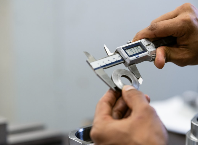
- Dimensional accuracy: Measurements within specified tolerances using appropriate gauging
- Surface finish: Ra values meeting specification for the application—tighter for Class A surfaces, more relaxed for hidden components
- Structural integrity: Material thickness maintained within acceptable limits throughout formed regions
- Geometric tolerances: Flatness, perpendicularity, and profile requirements per engineering specifications
- Material properties: Work hardening hasn't exceeded limits that compromise performance
| Defect Type | Primary Causes | Prevention Strategies | Detection Methods |
|---|---|---|---|
| Springback | Elastic recovery, high-strength materials | Overbending, bottoming, CNC compensation | Angle measurement, CMM inspection |
| Wrinkling | Insufficient blank holder force, excess material | Proper binder pressure, draw beads, blank optimization | Visual inspection, surface profilometry |
| Tearing/Splitting | Excessive strain, sharp radii, material limits | Material selection, multi-stage forming, grain orientation | Visual inspection, thickness measurement |
| Surface Defects | Tooling wear, debris, inadequate lubrication | Tool maintenance, proper lubricants, cleanliness protocols | Visual inspection, surface roughness testing |
Implementing quality control checks—including trial bends on a sheet metal bending brake and real-time monitoring during production—maintains consistency across batches. Training operators to understand materials, equipment, and potential failure modes equips them to adapt to variations and minimize defects before they become costly scrap.
With quality control fundamentals established, the next consideration becomes designing parts that avoid these problems from the start. Smart design choices during product development prevent manufacturing headaches down the line—and that's exactly where we'll focus next.
Design Best Practices for Formed Metal Parts
Here's a reality check: even the best metal forming tool can't save a poorly designed part. Wrinkling, cracking, and dimensional issues often trace back to design decisions made long before metal ever touched a die. The good news? Understanding a handful of design-for-manufacturability principles transforms problematic parts into easily produced components. Let's explore the rules that separate designs destined for the scrap bin from those that flow smoothly through production.
Design Rules for Formable Parts
Think of sheet metal forming like folding paper—except the paper fights back. Metal has minimum bend radii, maximum stretch limits, and specific behaviors that smart designers accommodate from the start. Ignoring these constraints doesn't just create quality problems; it drives up costs through secondary operations, tooling modifications, and rejected parts.
Bend radius requirements represent your most fundamental constraint. According to Xometry Pro's bending design guide, bend radius plays a critical role in ensuring structural integrity and avoiding cracks. A too-small radius can overstress the material, especially with thicker or less ductile metals. Larger radii improve formability and reduce springback.
The practical rule? Use a minimum inside bend radius equal to the material thickness for most applications. Harder materials like stainless steel or high-strength aluminum may require radii of 1.5T to 2T to prevent cracking. Here's what to keep in mind:
- Standard radii: Use consistent bend radii throughout your design when possible—it reduces tooling costs and simplifies setup
- Material-specific limits: Soft materials like copper tolerate tighter radii than hard materials like stainless steel
- Grain direction matters: Bending perpendicular to the rolling direction reduces cracking risk significantly
- Thickness considerations: Thicker materials require proportionally larger bend radii
Minimum flange lengths often surprise designers unfamiliar with forming constraints. As Protocase's bend radius documentation explains, geometry of tooling imposes a minimum bend dimension. The forming tool sheet metal contacts must have sufficient material to grip during the operation—too short, and the part won't hold position during bending.
Reference materials indicate minimum leg lengths typically range from 4mm for thin gauge aluminum to over 15mm for heavier stainless steel sections. When designing, ensure:
- Flanges extend at least 4× material thickness from the bend line
- Press brake tooling clearance is accommodated for successive bends
- Intermediate sections between bends remain longer than the flanges themselves
Hole placement relative to bends catches many first-time designers off guard. Holes positioned too close to bend lines distort during forming—stretching into ovals or tearing at their edges. The Protocase guidelines specify minimum hole distance values that ensure holes won't warp during bending operations.
The safe approach? Keep holes at least 2.5× material thickness away from bend lines—more for larger holes or tighter radii. Rounded slots oriented perpendicular to bends follow the same rules, while parallel slots require additional clearance to prevent edge deformation.
Optimizing Geometry for Manufacturing
Beyond basic constraints, strategic design choices dramatically affect manufacturing cost and quality. The shaping tools and processes available influence what geometries work best—and understanding these relationships lets you optimize parts before they ever reach the shop floor.
According to Xometry Pro's design recommendations, non-standard angles require specialized tooling, increasing cost and complexity. Standardizing angles saves money—stick to 90-degree bends where possible, reserving non-standard angles only when functionally necessary.
Key geometry optimization strategies include:
- Uniform wall thickness: Maintain consistent material thickness throughout to ensure predictable bending behavior
- Standard bend angles: 90° and 45° bends use common tooling; odd angles require custom setups
- Avoid successive tight bends: Allow adequate spacing between bends to accommodate tooling
- Symmetry where possible: Symmetric parts reduce setup complexity and handling errors
- Feature consolidation: Combine multiple features in progressive die operations when volumes justify tooling investment
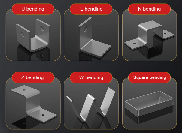
The reference materials highlight Z-bend considerations worth noting: these offset bends require minimum vertical step heights to accommodate tooling during forming. Steel and aluminum Z-bends typically need step heights ranging from 5mm to 15mm depending on material thickness and bend configuration.
| Design Feature | Minimum Requirement | Optimization Tip |
|---|---|---|
| Inside Bend Radius | ≥ Material thickness (1T) | Use 1.5T for stainless steel to prevent cracking |
| Minimum Flange Length | 4× material thickness | Increase for heavy gauge to improve grip during forming |
| Hole-to-Bend Distance | 2.5× material thickness | Move features further from bends when possible |
| Z-Bend Step Height | 5-15mm depending on gauge | Consult tooling specifications for specific values |
| Successive Bend Spacing | Greater than flange length | Allow clearance for die insertion on second bend |
From Concept to Production-Ready Design
Smart designs don't happen in isolation—they evolve through collaboration between designers, engineers, and manufacturing partners. The workflow from initial concept through prototyping to production benefits enormously from early manufacturing input.
Start with design intent, but verify manufacturability early. According to Geomiq's sheet metal design guide, understanding the K-factor is essential for accurate flat pattern development. This ratio—defining where the neutral axis falls within the material thickness—determines how much material gets consumed in each bend and directly affects flat blank dimensions.
The practical workflow looks like this:
- Concept phase: Establish functional requirements and preliminary geometry
- DFM review: Evaluate designs against forming constraints—bend radii, flange lengths, feature spacing
- Flat pattern development: Calculate accurate blank dimensions using appropriate K-factors (typically 0.3-0.5 depending on material and process)
- Prototyping: Validate designs with physical samples before committing to production tooling
- Production refinement: Optimize based on prototype feedback—adjust for springback, tooling access, and surface quality
Prototyping deserves special emphasis. Physical prototypes reveal issues CAD models miss—subtle springback effects, tooling interference problems, and assembly challenges only become apparent when you hold the actual part. For tools for forming sheet metal prototypes, consider starting with manual processes that don't require dedicated tooling investment.
The iterative relationship between design and manufacturing improves outcomes dramatically. Designers who understand forming constraints create better initial concepts. Manufacturers who engage early prevent costly redesigns later. Documentation—including specified tolerances, surface finish requirements, and forming notes—bridges the gap between design intent and production reality.
As Xometry Pro emphasizes, precise tolerancing is essential to ensure reliable manufacturing, especially when dealing with springback, tooling variation, or multi-step forming. General tolerances for bent features typically allow ±0.5° for angles and ±0.25mm for linear dimensions—tighter specifications require additional verification and often increase costs.
With design fundamentals established, the next challenge becomes selecting the optimal forming approach for your specific project. Volume requirements, complexity, materials, and budget all influence which method delivers the best results—decisions we'll explore in detail next.
Choosing the Right Forming Method for Your Project
You've mastered the fundamentals—materials, equipment, design principles, and quality control. Now comes the decision that ties everything together: which forming method actually makes sense for your specific project? This isn't a trivial choice. The wrong selection wastes money on unnecessary tooling, extends lead times, or produces parts that don't meet requirements. The right choice optimizes cost, quality, and timeline simultaneously. Let's build a decision framework that works.
Volume-Based Method Selection
Production volume stands as the single most influential factor in forming method selection. Why? Because tooling investments that make sense at 100,000 units become absurd at 100 units—and vice versa.
Consider the fundamental economics: According to Komaspec's fabrication process guide, progressive stamping tooling can cost from $10,000 to over $100,000, but the per-piece cost becomes very low at high volumes. Manual stamping tooling ranges from $250 to $50,000+, making it more accessible for medium-volume production. Meanwhile, laser cutting and CNC bending require no custom tooling at all.
Here's how volume typically maps to forming methods:
- Prototypes (1-10 units): Laser cutting combined with CNC bending or manual forming—no tooling investment, maximum flexibility
- Low volume (10-500 units): The same flexible processes work efficiently; a shop press or hydraulic press handles simple operations
- Medium volume (500-5,000 units): Manual stamping becomes viable; tooling investment spreads across enough parts to justify costs
- High volume (5,000-50,000 units): Progressive stamping and dedicated press machine operations deliver lowest per-part costs
- Mass production (50,000+ units): Fully automated stamping lines with integrated secondary operations maximize efficiency
The transition points aren't absolute—they shift based on part complexity, material costs, and tolerance requirements. But understanding these general ranges prevents the common mistake of over-investing in tooling for small runs or under-investing for large ones.
For designs still in development, the guidance from Komaspec proves especially relevant: for designs not fully prototyped or tested, avoid proceeding with tooling or long lead-time processes. Instead, use the fastest approach to create physical samples for field testing and certification. Once the design stabilizes, tooling can be cut for larger volume orders to reduce product cost.
Balancing Quality Requirements with Budget
Sounds complex? It can be—but breaking quality requirements into specific parameters simplifies the decision. Different forming methods deliver different precision levels, and paying for tolerance you don't need wastes money.
The precision hierarchy looks like this:
| Forming Method | Typical Tolerance | Tooling Cost | Per-Part Cost (High Volume) | Best For |
|---|---|---|---|---|
| Progressive Stamping | ±0.05mm to 0.10mm | $10k-$100k+ | Very Low | High-volume precision parts |
| Manual Stamping | ±0.05mm to 0.10mm | $250-$50k | Low | Medium-volume tight tolerances |
| CNC Punching | ±0.10mm | Low (standard tools) | Low to Medium | Parts with multiple holes/features |
| Laser Cutting | ±0.10mm linear | None | Medium | Complex geometries, prototypes |
| CNC Bending | ±0.18mm | None to Low | Medium | Angular components, brackets |
| Shearing | ±0.50mm | None | Medium | Simple straight cuts, blanks |
Notice the trade-off: higher precision generally means higher tooling investment. A brake press operation achieving ±0.18mm tolerance costs far less to set up than progressive stamping achieving ±0.05mm—but at 50,000 units, that stamping investment pays for itself many times over.
Beyond dimensional tolerance, consider these quality factors:
- Surface finish requirements: Class A automotive surfaces demand different processes than hidden structural components
- Material thickness consistency: Deep drawing and hydroforming maintain wall thickness better than aggressive stamping operations
- Structural integrity: Seamless deep-drawn parts outperform welded assemblies for pressure vessels
- Secondary operations: Some forming methods require deburring, tapping, or additional finishing—factor these costs into total part cost
As Sinoway Industry's process comparison notes, deep drawing produces parts with enhanced strength and durability due to cold working—but initial setup costs make it less economical for small production runs. Stamping offers faster production speeds and lower setup costs but limited complexity for deep, concave shapes.
When to Choose Custom Tooling vs Standard Processes
The custom tooling decision deserves careful analysis. Custom dies enable remarkable precision and speed—but they also lock you into specific designs and require significant upfront investment.
According to Wiley Metal's fabrication analysis, custom fabrication provides greater flexibility for low-volume runs, pilot programs, prototypes, or new product introductions. It allows teams to iterate quickly, test concepts in the field, and adapt without being locked into large inventory investments or outdated specs.
Consider custom tooling when:
- Production volumes exceed 3,000-5,000 units annually
- Part geometry requires features impossible with standard tooling
- Tolerance requirements exceed what flexible processes achieve
- Per-part cost reduction justifies the tooling investment
- The design is stable and unlikely to change
Stick with standard processes when:
- Design iteration is still ongoing or expected
- Volumes remain below tooling break-even points
- Lead time constraints prevent 30-55 day tooling development
- Part geometry works with standard dies and punches
- Budget constraints prevent upfront tooling investment
For tube and pipe forming applications, similar logic applies. A hydraulic pipe bender handles custom bends without dedicated tooling, while pipe bending hydraulic systems with specialized dies optimize high-volume production. An exhaust pipe bender designed for automotive applications illustrates this—standard equipment handles prototypes and repairs, but dedicated mandrel bending setups serve production exhaust systems.
The best approach isn't always the most advanced—it's the one that matches your specific volume, quality, and timeline requirements at the lowest total cost.
The welding positioner used in downstream assembly operations also influences forming method selection. If parts require extensive welding, designing for weld access during the forming stage prevents costly rework. The shop press or press machine capacity in your assembly area may also constrain maximum part size or require design modifications.
Lead time deserves final consideration. According to Komaspec's process data, laser cutting and CNC bending can deliver sampling within 5 days and production within 10 days. Manual stamping requires 30-40 days for tooling plus 15 days for production. Progressive stamping extends to 45-55 days for tooling development.
When validating your forming method selection before committing to production tooling, rapid prototyping capabilities become invaluable. Manufacturers offering 5-day turnaround on prototypes let you test designs physically—identifying issues that CAD models miss. Comprehensive DFM (Design for Manufacturability) support during this phase catches problems early, when changes cost nothing compared to modifying hardened production tooling. For automotive applications requiring chassis, suspension, or structural components, partnering with manufacturers providing both rapid prototyping and IATF 16949-certified mass production capabilities—like Shaoyi (Ningbo) Metal Technology—streamlines the transition from validated prototypes to automated production.
With your forming method selected, the final step involves taking your project from planning to execution. Understanding what to look for in manufacturing partners—and how to evaluate their capabilities—ensures your carefully chosen approach delivers the results you expect.
Taking Your Sheet Metal Forming Project Forward
You've absorbed a tremendous amount of information—from forming fundamentals and equipment options to material selection and quality control strategies. Now comes the moment of truth: transforming that knowledge into successful production. Whether you're sourcing simple brackets or complex automotive assemblies, the decisions you make in the next phase determine whether your project succeeds or stumbles. Let's distill everything into actionable guidance that gets results.
Key Takeaways for Your Forming Project
Before reaching out to potential manufacturing partners, crystallize your project requirements. The clearer your specifications, the more accurate your quotes—and the fewer surprises during production.
Consider these critical decision points:
- Material selection: Match ductility, strength, and corrosion resistance to your application requirements—don't over-specify and inflate costs
- Process choice: Let production volume drive your method selection—prototypes and low volumes favor flexible processes, while high volumes justify tooling investment
- Tolerance requirements: Specify only what you actually need—tighter tolerances increase costs without adding value if the application doesn't demand precision
- Quality metrics: Define surface finish, dimensional accuracy, and structural requirements upfront to avoid misaligned expectations
- Design optimization: Ensure bend radii, flange lengths, and hole placements comply with forming constraints before requesting quotes
The most successful sheet metal forming projects share one characteristic: clear communication between designers, engineers, and manufacturing partners from the earliest stages.
Review your flat pattern calculations, verify K-factors for your specific material and thickness, and confirm that your design accommodates the forming equipment you're targeting. These details matter—correcting them before production costs nothing, while fixing them afterward costs everything.
Evaluating Manufacturing Partners
Choosing the right fabrication partner matters as much as selecting the right forming process. According to APX Enclosures' manufacturing selection guide, a manufacturer's capabilities and equipment can make or break your project—ensure they have the machinery and technology to handle your requirements efficiently.
What separates capable partners from inadequate ones? Look for these indicators:
- Industry certifications: Quality management credentials demonstrate systematic approaches to consistency and continuous improvement
- Prototyping capabilities: Partners offering rapid prototyping let you validate designs physically before committing to production tooling
- DFM support: Comprehensive Design for Manufacturability feedback catches problems early when changes remain inexpensive
- Equipment breadth: Manufacturers with diverse forming capabilities can recommend optimal approaches rather than forcing projects into their limited capacity
- Communication responsiveness: Quote turnaround time indicates how the relationship will function during production
For automotive applications specifically, the IATF 16949 certification represents the gold standard. As the International Automotive Task Force designed it, this certification signifies that a manufacturer has developed a process-oriented quality management system providing continual improvement, defect prevention, and reduction of variation and waste. Major automotive OEMs including BMW, Ford, and Stellantis require this certification from their supply chain partners.
Beyond certifications, evaluate practical capabilities. Can the manufacturer handle your production volumes—whether that's 50 prototypes or 500,000 annual units? Do they offer secondary operations like welding tables for assembly, drill presses for additional machining, or pipe stands for handling tubular components? Understanding the full scope of their capabilities prevents surprises when your project scales.
| Evaluation Criteria | What to Look For | Red Flags |
|---|---|---|
| Certifications | IATF 16949, ISO 9001, industry-specific credentials | No quality management system documentation |
| Prototyping Speed | 5-day or faster turnaround for initial samples | Weeks-long prototype lead times |
| DFM Support | Proactive design feedback before quoting | "Build it exactly as drawn" without optimization suggestions |
| Quote Responsiveness | 12-24 hour turnaround on standard requests | Multiple days for basic quote responses |
| Equipment Capabilities | Range from benchtop drill press to production stamping | Limited to single process type |
| Volume Flexibility | Handles prototypes through mass production | Minimum order quantities excluding development work |
As APX Enclosures emphasizes, quality control and certifications are the seal of approval in the sheet metal world—verify that manufacturers adhere to industry standards and regulations to guarantee the quality and integrity of your project.
Next Steps Toward Production
Ready to move forward? Here's your action roadmap:
Step 1: Finalize your specifications. Document material requirements, tolerance expectations, surface finish standards, and production volumes. Include 2D drawings and 3D models where possible.
Step 2: Request quotes from qualified partners. Don't just send RFQs blindly—select manufacturers whose capabilities align with your project requirements. For automotive chassis, suspension, and structural components, seek partners with IATF 16949 certification and demonstrated experience in your application area.
Step 3: Evaluate responses holistically. The lowest quote rarely represents the best value. Consider DFM feedback quality, prototype lead times, and communication responsiveness alongside pricing.
Step 4: Validate with prototypes. Before committing to production tooling, produce physical samples. Test fit, function, and finish. This investment prevents exponentially larger costs from discovering problems during mass production.
Step 5: Establish clear terms. Document tolerances, inspection criteria, delivery schedules, and communication protocols. Ambiguity breeds problems.
Successful manufacturing partnerships aren't transactional—they're collaborative relationships where both parties invest in mutual success.
For readers exploring sheet metal forming products for automotive applications, manufacturers offering comprehensive capabilities—from 5-day rapid prototyping through automated mass production—simplify the journey from concept to volume manufacturing. Shaoyi (Ningbo) Metal Technology exemplifies this approach, combining IATF 16949-certified quality systems with 12-hour quote turnaround and dedicated DFM support for chassis, suspension, and structural components.
Workshop-level projects benefit from different resources. A bench drill press handles hole creation before forming, welding tables provide stable surfaces for assembly operations, and proper fixturing using pipe stands keeps tubular components organized during processing.
Whatever your scale—prototype development or production ramp-up—the principles remain consistent. Understand your requirements clearly. Select forming methods matching your volume and quality needs. Partner with manufacturers whose capabilities and certifications align with your application. And maintain open communication throughout the process.
Sheet metal forming products surround us because the processes that create them deliver unmatched combinations of strength, precision, and cost-effectiveness. Armed with the knowledge from this guide, you're equipped to leverage those same advantages for your projects—picking the right method every time.
Frequently Asked Questions About Sheet Metal Forming Products
1. What products are made from sheet metal?
Sheet metal forming products span virtually every industry. Common examples include automotive body panels, chassis components, and fuel tanks; aerospace fuselage sections and structural parts; household appliances like refrigerator housings and washing machine drums; HVAC ductwork and electrical enclosures; beverage cans and cookware; medical device housings; and furniture components. The process excels at creating strong, lightweight parts with complex geometries while maintaining material integrity and minimizing waste.
2. How to stiffen sheet metal parts?
Several techniques effectively stiffen sheet metal formed parts. Integrating ribs into designs dramatically increases stiffness and overall strength. Adding flanges along edges or bends distributes stress more evenly, reducing failure likelihood under load. Bead rolling creates raised lines that reinforce panels while adding visual interest. Work hardening during the forming process itself increases material strength. For deeper draws, the cold working inherent in the process enhances durability. Proper material thickness selection and strategic bend placement also contribute to structural rigidity.
3. What is the difference between stamping and deep drawing?
Stamping uses a punch and die to create shaped components through blanking, piercing, embossing, or bending operations—ideal for high-volume production of brackets, panels, and hardware. Deep drawing transforms flat blanks into seamless three-dimensional hollow shapes by forcing material through a die cavity, producing cups, cylinders, and enclosures without joints or welds. While stamping offers faster production speeds and lower setup costs, deep drawing creates parts with enhanced structural integrity suitable for pressure vessels and liquid-tight applications.
4. How do I choose the right sheet metal forming process for my project?
Match your forming process to production volume, part complexity, and quality requirements. For prototypes and low volumes under 500 units, laser cutting with CNC bending offers flexibility without tooling investment. Medium volumes between 500-5,000 units justify manual stamping tooling. High volumes exceeding 5,000 units benefit from progressive stamping's low per-part costs. Consider tolerance needs—stamping achieves ±0.05mm while CNC bending typically delivers ±0.18mm. Rapid prototyping services with 5-day turnaround help validate designs before committing to production tooling.
5. What certifications should I look for in a sheet metal forming manufacturer?
For automotive applications, IATF 16949 certification represents the industry gold standard, signifying process-oriented quality management with continual improvement and defect prevention—required by major OEMs including BMW, Ford, and Stellantis. ISO 9001 demonstrates general quality management compliance. Beyond certifications, evaluate prototyping speed (5-day turnaround indicates capability), DFM support quality, quote responsiveness (12-hour turnaround suggests efficiency), and equipment breadth covering your volume range from prototypes through mass production.