 Small batches, high standards. Our rapid prototyping service makes validation faster and easier —

Metal CNC Sheet Fabrication: Essential Points For Smarter Sourcing
Understanding CNC Sheet Metal Processing Fundamentals
Imagine transforming a flat, unremarkable metal sheet into a complex precision component with tolerances measured in fractions of a millimeter. That's exactly what CNC sheet metal processing accomplishes every day across manufacturing facilities worldwide. But what makes this technology so revolutionary, and why should you understand it before sourcing your next project?
From Flat Stock to Finished Parts
At its core, the cnc meaning refers to Computer Numerical Control - a technology where pre-programmed software dictates the movement of machinery and tools. When applied to sheet metal fabrication, this digital control transforms thin metal sheets through cutting, bending, punching, and forming operations with remarkable accuracy.
Unlike traditional CNC machining that carves parts from solid blocks of material, cnc sheet metal processing starts with flat stock - typically ranging from thin gauge aluminum to heavy steel plates. The process shapes these sheets into finished components through subtractive and formative operations, making it inherently more material-efficient for many applications.
According to BVS Blechtechnik, CNC sheet metal processing encompasses all manufacturing processes where sheet metal is punched, lasered, bent, or welded by computer-controlled machines. This integration allows even complex geometries to be implemented with precision and repeatability - ideal for series production with consistently high quality.
The Digital Revolution in Metal Forming
What truly sets sheet metal cnc apart from manual methods? The answer lies in digital precision and process control. Every production step is digitally controlled, precisely documented, and reproducible at any time. This systematic approach delivers benefits that manual fabrication simply cannot match.
CNC technology enables repeatability and precision impossible with manual methods - guaranteeing not only dimensional accuracy but also outstanding cost efficiency, especially for medium and large quantities.
The advantages of cnc metal processing extend across multiple dimensions:
- High dimensional accuracy - Parts consistently meet tight tolerance specifications
- Low waste - Efficient material utilization through optimized nesting
- Predictable processes - Reliable results across small, medium, and large batch sizes
- Comprehensive capabilities - Multiple operations from cutting through surface finishing under one production umbrella
Modern metal fabrication facilities leverage CAD/CAM software to translate designs directly into machine instructions. This seamless digital workflow eliminates interpretation errors and enables rapid iteration during prototyping phases. Whether you're producing a single prototype or thousands of identical components, the programming ensures each part matches your specifications exactly.
Throughout this guide, you'll discover the essential knowledge needed for smarter sourcing decisions. We'll explore cutting technologies - from laser to waterjet - and help you understand which method suits your specific requirements. Material selection guidance will cover everything from lightweight aluminum alloys to robust stainless steel grades. You'll learn about gauge specifications, complete fabrication workflows, and design principles that reduce costs while improving quality. By the end, you'll have the foundational understanding needed to communicate effectively with manufacturers and optimize your sheet metal fabrication projects for success.

Comparing CNC Cutting Technologies for Sheet Metal
Choosing the wrong cnc metal cutting machine can cost you thousands in wasted material and lost production time. With multiple cutting technologies available - each with distinct strengths and limitations - how do you determine which machine to cut metal best fits your project requirements?
Let's break down the four primary CNC cutting technologies dominating today's sheet metal cutting machine landscape: laser cutting, plasma cutting, waterjet cutting, and CNC routing.
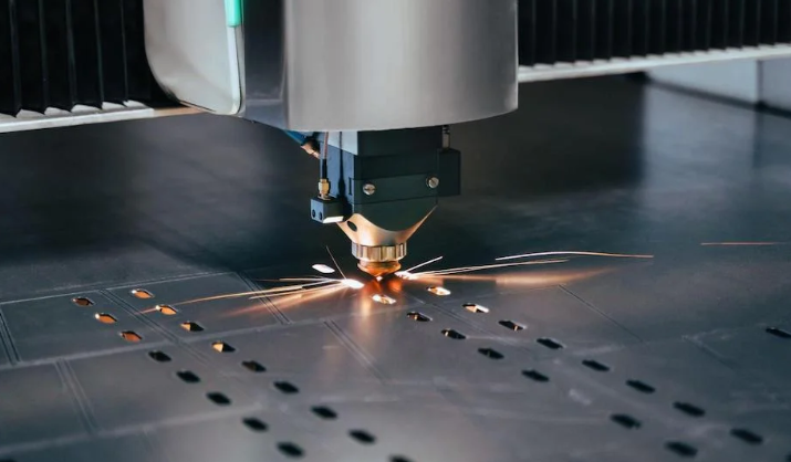
Laser Cutting Precision and Speed Advantages
When your project demands surgical precision on thin materials, a laser cutter delivers unmatched results. Laser cutting employs a focused beam of light - typically from CO2 or fiber laser sources - to melt, burn, or vaporize material along a programmed path.
What makes laser cutting the go-to choice for precision work?
- Exceptional tolerances - Achieving ±0.001" to ±0.005" on thin gauge materials
- Superior edge quality - Smooth, burr-free edges often requiring no secondary finishing
- Intricate detail capability - Fine features, small holes, and complex geometries
- Minimal heat-affected zone - Approximately 0.006" to 0.020" on thin sheets
Fiber lasers dominate thin material cutting, achieving exceptional speeds on sheets under 1/4" thick. However, cutting speed decreases significantly as material thickness increases, with dramatic slowdowns on materials over 1" thick. For applications like electronics enclosures, medical device components, and precision brackets, laser cutting cutting technology offers the best combination of speed and accuracy.
Plasma Cutting for Thick Conductive Metals
Need to process thick steel plates quickly and cost-effectively? Plasma cutting uses an accelerated jet of hot plasma - reaching temperatures up to 45,000°F - to cut through electrically conductive materials. According to StarLab CNC, modern CNC plasma tables handle an impressive thickness range from 0.018" to 2", with some systems capable of cutting up to 6" thick.
This metal cutter technology excels in:
- Structural steel fabrication
- Heavy equipment manufacturing
- Shipbuilding and marine applications
- HVAC and ductwork production
A high-powered plasma system can cut 1/2" mild steel at speeds exceeding 100 inches per minute, making it the fastest option for medium to thick metal plates.
When Waterjet Outperforms Thermal Methods
Sometimes heat is the enemy. Waterjet cutting uses high-pressure water - operating at pressures up to 90,000 PSI and often mixed with abrasive particles - to erode material without generating heat. This cold-cutting process preserves material properties that thermal methods can compromise.
Choose waterjet when you need:
- Zero heat-affected zone - No material warping, hardening, or structural changes
- Maximum material versatility - Cuts metals, stone, glass, composites, and more
- Thick material capability - Handling materials up to 8" thick or more
- Heat-sensitive applications - Aerospace components, medical devices, and specialized alloys
According to Wurth Machinery, the waterjet market is projected to reach over $2.39 billion by 2034, reflecting growing demand for heat-free cutting solutions.
CNC Cutting Technology Comparison
Understanding the specifications of each metal cutting machine helps you match technology to project requirements:
| Specification | Laser Cutting | Plasma Cutting | Waterjet Cutting | CNC Routing |
|---|---|---|---|---|
| Material Thickness Range | 0.001" - 1" (optimal under 1/4") | 0.018" - 2" (up to 6" capable) | Up to 8"+ any material | Up to 2" (material dependent) |
| Tolerance Capability | ±0.001" to ±0.005" | ±0.010" to ±0.030" | ±0.003" to ±0.010" | ±0.005" to ±0.015" |
| Edge Quality | Excellent - burr-free, smooth | Good - may require finishing | Very Good - smooth, no burrs | Good - depends on tooling |
| Heat-Affected Zone | 0.006" - 0.020" | 0.125" - 0.250" | None | Minimal (friction-based) |
| Cutting Speed | Fast on thin materials | Fastest on thick metals | Slow (5-20 IPM typical) | Moderate |
| Ideal Applications | Electronics, medical, precision parts | Structural steel, heavy equipment | Aerospace, composites, stone | Aluminum, plastics, soft metals |
Understanding Kerf and Material Selection
Kerf - the width of material removed during cutting - directly impacts your design and material selection. Each cutting method produces different kerf characteristics:
- Laser cutting - Narrowest kerf (0.004" - 0.015"), ideal for intricate nesting and maximum material yield
- Plasma cutting - Wider kerf (0.045" - 0.150"), requires larger part spacing in nest layouts
- Waterjet cutting - Moderate kerf (0.030" - 0.050"), adjustable based on nozzle and abrasive
- CNC routing - Variable kerf based on tool diameter selection
When designing parts for CNC cutting, account for kerf width in your CAD files. Tighter nesting becomes possible with laser cutting, while plasma requires more generous spacing between parts. This consideration directly affects material costs - especially critical when working with expensive alloys or high-volume production runs.
With cutting technology fundamentals established, your next consideration becomes equally critical: which material should you specify for your project? The answer depends on performance requirements, fabrication method compatibility, and cost constraints.
Material Selection Guide for CNC Sheet Metal Projects
You've identified the right cutting technology for your project. Now comes an equally important decision: which material will deliver the performance, durability, and cost-effectiveness your application demands? Selecting the wrong aluminum sheet or stainless steel sheet can lead to fabrication challenges, premature part failure, or unnecessary expense.
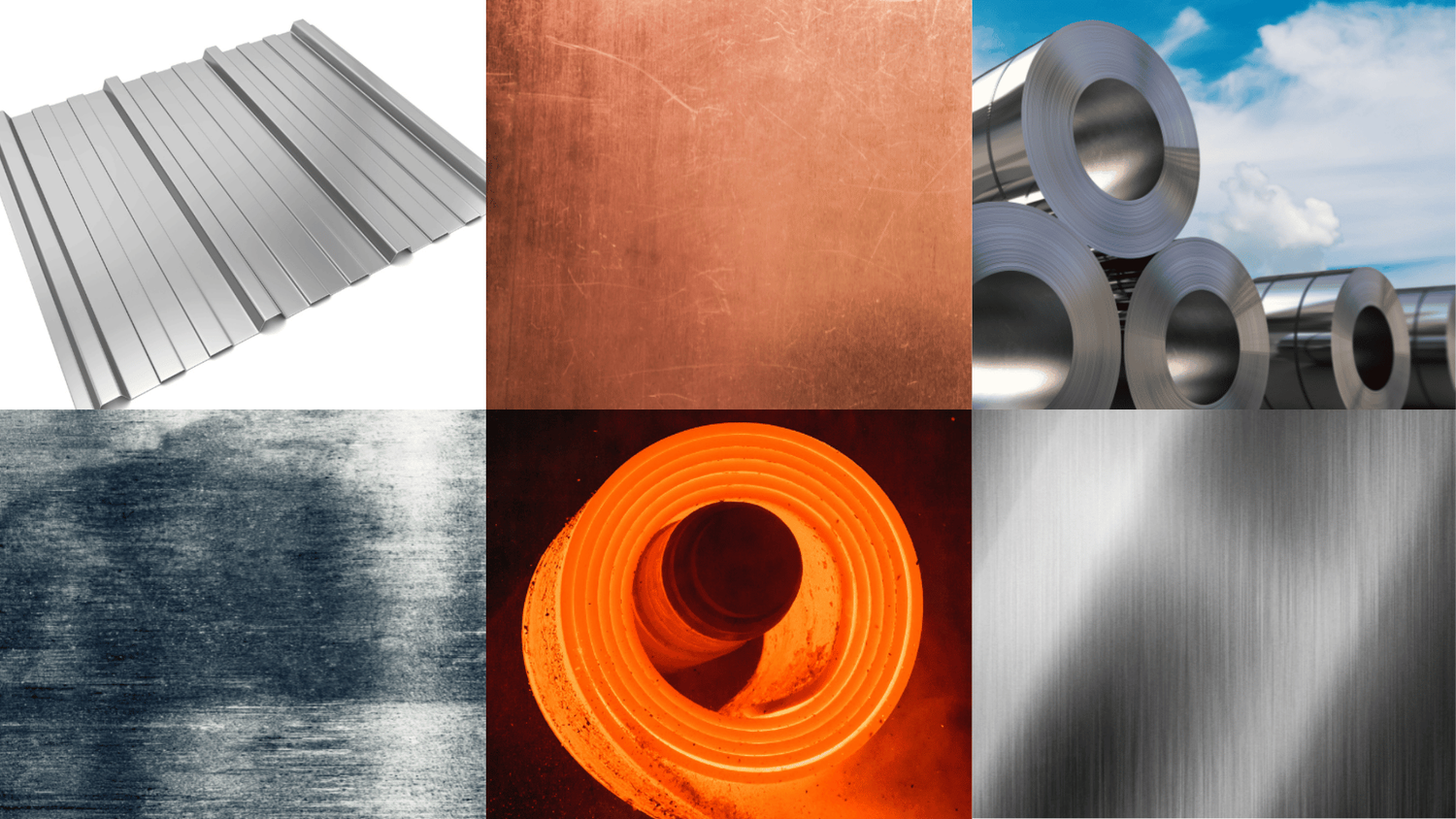
Let's explore the six most common materials for CNC sheet metal applications and understand what makes each one suited to specific requirements.
Aluminum Alloys for Lightweight Precision
When weight savings matter - think aerospace, automotive, or portable electronics - aluminum sheet metal delivers an unbeatable strength-to-weight ratio. According to FACTUREE, aluminum alloys convince through low weight, high stability, and excellent corrosion resistance thanks to a natural oxide layer that keeps sheets rust-free and ideal for outdoor use.
Among aluminum alloys, 6061 stands as the workhorse for general-purpose applications. This precipitation hardening alloy contains magnesium and silicon as its major alloying elements, offering good mechanical properties and excellent weldability. According to Ferguson Perforating, the 6061 aluminium yield strength varies dramatically based on temper:
- 6061-O (annealed) - Maximum yield strength of 8,000 psi (55 MPa)
- 6061-T4 temper - Yield strength of at least 16,000 psi (110 MPa)
- 6061-T6 temper - Yield strength of at least 35,000 psi (241 MPa) with ultimate tensile strength of 42,000 psi (290 MPa)
Why does temper matter for your project? After welding 6061, the properties near the weld revert to those of 6061-O - a loss of strength around 80%. The good news? You can re-heat-treat the entire piece to restore T4 or T6 properties. This makes 6061 highly weldable using TIG or MIG processes, though you must account for post-weld treatment in your production planning.
Aluminum processes beautifully through laser cutting with appropriate settings and excels in punching and bending operations. However, its high reflectivity demands specialized laser configurations to prevent beam reflection issues.
Stainless Steel Grades and Their Machinability
Need exceptional corrosion resistance, hygiene compliance, or an elegant appearance? Stainless steel sheet delivers all three. According to Prototek, stainless steel's key characteristics include biocompatibility, corrosion resistance, ductility, high tensile strength, and temperature resistance - making it ideal for applications where quality and stability are paramount.
Understanding stainless steel machining requirements helps you select the right grade:
- 304 Stainless Steel - The most common grade with 84,000-170,000 psi tensile strength and 40% machinability rating. Ideal for food equipment, architectural features, and general-purpose applications.
- 316 Stainless Steel - Enhanced corrosion resistance with 76,000-170,000 psi tensile strength. The go-to choice for marine environments, chemical processing, and medical devices. Its 36% machinability rating means slightly slower cutting speeds.
- 301 Stainless Steel - Highest strength potential at 85,000-210,000 psi ultimate tensile strength. Perfect for springs and high-strength structural applications.
Stainless steel machining presents unique challenges. The material work-hardens during cutting, requiring sharp tooling and consistent feed rates. Laser cutting, punching, bending, and welding all work well with stainless steel sheet, though processing costs run higher than mild steel due to slower cutting speeds and increased tool wear.
Mild Steel, Copper, Brass, and Titanium Options
Beyond aluminum and stainless steel, several other materials serve specific CNC sheet metal applications:
Mild Steel (Carbon Steel) - The most cost-effective option for structural applications. It offers high strength, excellent weldability, and outstanding robustness. However, it requires protective coatings like galvanizing or powder coating to prevent corrosion.
Copper - Boasts the highest electrical and thermal conductivity of all common metals. Its ductility makes it easy to form, though its high reflectivity makes laser cutting demanding. Ideal for busbars, electrical contacts, heat exchangers, and decorative elements.
Brass vs Bronze - Both are copper alloys, but they serve different purposes. Brass (copper-zinc) offers excellent machinability and acoustic properties, making it popular for musical instruments and decorative hardware. Bronze (copper-tin) provides superior wear resistance and marine corrosion resistance. Both process well through standard sheet metal operations.
Titanium - The ultimate choice when you need exceptional strength-to-weight ratio and corrosion resistance in demanding environments. Common in aerospace and medical implant applications, titanium requires specialized cutting parameters and commands premium pricing.
Material Properties Comparison
This comparison helps you match material properties to your application requirements:
| Material | Tensile Strength (psi) | Formability | Corrosion Resistance | Relative Cost | Best Applications |
|---|---|---|---|---|---|
| 6061 Aluminum (T6) | 42,000 | Excellent | Very Good | $$ | Aerospace, automotive, electronics housings |
| 304 Stainless Steel | 84,000-170,000 | Good | Excellent | $$$ | Food processing, architecture, appliances |
| 316 Stainless Steel | 76,000-170,000 | Good | Superior | $$$$ | Marine, chemical, medical devices |
| Mild Steel | 50,000-80,000 | Excellent | Poor (needs coating) | $ | Structural, machinery, general fabrication |
| Copper | 32,000-45,000 | Excellent | Very Good | $$$$ | Electrical, heat exchangers, decorative |
| Titanium | 63,000-170,000 | Moderate | Excellent | $$$$$ | Aerospace, medical implants, marine |
Industry-Specific Selection Criteria
Your industry often dictates material requirements before other factors come into play:
- Automotive applications - Prioritize mild steel for structural components, aluminum for weight-critical parts, and stainless steel for exhaust systems and decorative trim
- Aerospace projects - Specify 6061 or 7075 aluminum for airframe components, titanium for high-stress applications, and stainless steel for fasteners and fittings
- Electronics enclosures - Choose aluminum for heat dissipation and EMI shielding, stainless steel for ruggedized applications, or copper for specialized thermal management
- Medical devices - Require 316 stainless steel or titanium for biocompatibility, with stringent surface finish requirements
- Food and beverage equipment - Mandate 304 or 316 stainless steel for hygiene compliance and cleaning resistance
Material choice directly affects your cutting method selection. Reflective materials like aluminum and copper require fiber lasers or specialized settings. Thick mild steel processes fastest through plasma cutting. Heat-sensitive alloys demand waterjet cutting to preserve material properties.
With material selection clarified, understanding gauge specifications becomes essential - because the thickness you specify determines which fabrication processes apply and what tolerances you can realistically achieve.
Sheet Metal Gauge and Thickness Specifications
Ever wondered why a "14 gauge" steel sheet measures differently than a "14 gauge" aluminum sheet? The gauge system's counterintuitive nature - where lower numbers mean thicker material - confuses even experienced engineers. Yet mastering this seemingly arcane measurement system directly impacts your fabrication costs, process selection, and part performance.
According to Ryerson, the gauge system traces its origins to 19th century British iron wire manufacturing. During an era without universal thickness standards, craftsmen adopted gauge as a convenient measurement - and the convention persisted. Today, you must reference the correct sheet metal gauge chart for each material type, since gauge numbers translate to different actual thicknesses depending on whether you're working with steel, aluminum, or copper.
Decoding the Gauge System for Steel and Aluminum
Here's the fundamental rule: the higher the gauge number, the thinner the sheet. But the relationship isn't linear, and it varies by material. Let's examine the most commonly specified gauge sizes with their actual thickness measurements:
| Gauge | Steel (inches) | Steel (mm) | Stainless Steel (inches) | Stainless Steel (mm) | Aluminum (inches) | Aluminum (mm) |
|---|---|---|---|---|---|---|
| 10 | 0.1345 | 3.416 | 0.1406 | 3.571 | 0.1019 | 2.588 |
| 11 | 0.1196 | 3.038 | 0.1250 | 3.175 | 0.0907 | 2.304 |
| 12 | 0.1046 | 2.659 | 0.1094 | 2.779 | 0.0808 | 2.052 |
| 14 | 0.0747 | 1.897 | 0.0781 | 1.984 | 0.0641 | 1.628 |
| 16 | 0.0598 | 1.519 | 0.0625 | 1.588 | 0.0508 | 1.290 |
| 18 | 0.0478 | 1.214 | 0.0500 | 1.270 | 0.0403 | 1.024 |
| 20 | 0.0359 | 0.912 | 0.0375 | 0.952 | 0.0320 | 0.813 |
| 22 | 0.0299 | 0.759 | 0.0313 | 0.794 | 0.0253 | 0.643 |
| 24 | 0.0239 | 0.607 | 0.0250 | 0.635 | 0.0201 | 0.511 |
Notice something critical? The 14 gauge steel thickness measures 0.0747 inches (1.897 mm), while 14 gauge aluminum comes in at only 0.0641 inches (1.628 mm) - a 14% difference. Similarly, 11 gauge steel thickness runs approximately 0.1196 inches (3.038 mm). These variations matter significantly when you're calculating bend allowances or specifying cutting parameters.
According to PEKO Precision, for RFQs and engineering drawings, you should list both the gauge and the actual thickness - for example, "16 ga steel (0.0598 in / 1.519 mm)" - to eliminate ambiguity between you and your fabricator.
Thickness Limits Across Cutting Technologies
Material thickness directly determines which cutting and forming processes apply to your project. Here's how thickness affects your options:
- Laser cutting - Excels on thin gauge materials up to approximately 1/4" (6mm). Performance drops significantly on thicker steel plates, with dramatically slower speeds above 1/2"
- Plasma cutting - Optimal for medium to heavy steel plate applications from 1/8" to 2". Some systems handle steel plates up to 6" thick
- Waterjet cutting - Handles the broadest thickness range, cutting materials up to 8" or more regardless of heat sensitivity
- CNC punching - Generally limited to materials under 1/4" thick, with optimal performance on 10-20 gauge sheets
Thickness also governs bending requirements. The minimum inside bend radius typically equals 1x the material thickness for soft materials like aluminum, increasing to 2x or more for harder alloys and stainless steel. A 14 gauge steel sheet bends with a tighter radius than 11 gauge steel simply because less material must stretch and compress during forming.
Process Selection by Gauge Range
Matching your gauge specification to the right fabrication approach prevents costly process mismatches:
- Thin gauge (20-28 gauge) - Ideal for laser cutting, stamping, and light forming. Common in electronics enclosures, HVAC components, and decorative applications
- Medium gauge (14-18 gauge) - The sweet spot for most CNC sheet metal work. Compatible with laser, punching, and standard press brake bending. Used extensively in automotive brackets, appliance panels, and industrial equipment
- Heavy gauge (10-12 gauge) - Requires more powerful equipment. Still suitable for laser cutting but transitions toward plasma for cost efficiency. Structural applications, heavy equipment, and chassis components
- Plate thickness (3/16" and above) - Generally considered steel plate rather than sheet metal. Plasma and waterjet cutting dominate, with specialized heavy-tonnage press brakes for forming
Cost and Design Implications
Your gauge selection ripples through the entire project cost structure. Thicker materials cost more per square foot - but that's just the beginning. Heavier gauge sheets require:
- Higher-powered cutting equipment with slower processing speeds
- Greater press brake tonnage for bending operations
- Larger bend radii that may affect part geometry
- Stronger fasteners and joining methods
- More robust handling and shipping considerations
For precision applications, always verify actual thickness with a caliper or micrometer before production. Mill tolerances allow variation within each gauge specification, and thickness deviations directly affect bend allowance calculations, K-factor values, and final part dimensions.
Understanding gauge specifications sets the foundation - but cutting is only the first step. Your parts must then move through bending, forming, and joining operations to become finished components ready for assembly.
Beyond Cutting The Complete Fabrication Workflow
Your parts have been cut with precision - but they're still flat. How do they transform into three-dimensional components ready for assembly? The answer lies in understanding the complete cnc sheet metal fabrication workflow, where bending, forming, punching, and joining operations turn simple blanks into functional parts.
Each fabrication step introduces variables that affect quality, cost, and lead time. Mastering this workflow helps you communicate effectively with manufacturers and make smarter sourcing decisions.
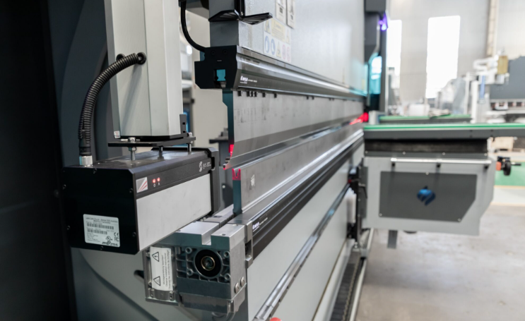
Precision Bending and Forming Techniques
CNC press brakes represent the backbone of sheet metal forming operations. These powerful machines use precision-controlled rams and dies to create accurate bends at programmed angles and positions. But achieving consistent results requires understanding the science behind the process.
Bend allowance calculations determine how much material stretches during bending - and getting this wrong throws off every dimension on your finished part. The formula accounts for material thickness, bend angle, inside radius, and the material's K-factor (the ratio of neutral axis location to material thickness). Modern CNC press brakes incorporate these calculations automatically, but your design files must specify the correct values.
What makes CNC press brakes superior to manual methods?
- Programmable back gauges - Position material precisely for each bend in a sequence
- Angle measurement systems - Real-time monitoring ensures bend accuracy within ±0.5 degrees or better
- Crowning compensation - Adjusts for deflection across long bends to maintain consistent angles
- Multi-axis control - Handles complex parts requiring bends in multiple planes
Forming operations extend beyond simple bends. Roll forming creates curved sections, while specialized tooling produces hems, seams, and embossed features. Each operation must follow the correct sequence - and that's where workflow planning becomes critical.
The Typical Fabrication Sequence
From initial design through finished part, cnc sheet metal fabrication follows a logical progression. Understanding this sequence helps you anticipate lead times and identify cost optimization opportunities:
- Design and engineering review - CAD files are analyzed for manufacturability, with DFM feedback provided to optimize the design for production
- Material procurement - Sheet stock is ordered in appropriate gauge, alloy, and quantity based on nesting efficiency calculations
- Flat pattern development - 3D designs are unfolded into 2D cutting patterns with bend allowances calculated
- CNC cutting - Laser, plasma, or waterjet cutting creates flat blanks with all holes, slots, and edge features
- Punching and shearing - High-volume production may incorporate CNC turret punching for repetitive hole patterns and shearing for straight cuts
- Deburring and edge preparation - Removing sharp edges and preparing surfaces for subsequent operations
- Bending and forming - CNC press brakes create all required bends in the proper sequence
- Joining operations - Welding, hardware insertion, or mechanical fastening assembles multi-piece components
- Surface finishing - Powder coating, plating, anodizing, or other treatments provide protection and aesthetics
- Quality inspection - Dimensional verification and documentation confirm parts meet specifications
Secondary Operations That Complete Your Parts
Punching and Shearing for High-Volume Production
When your project involves thousands of identical parts with repetitive hole patterns, CNC turret punching offers significant cost advantages over laser cutting. These machines use interchangeable tooling to punch holes, slots, and formed features at high speeds - often processing simple parts in seconds rather than minutes.
Shearing operations provide the most economical straight cuts for high-volume blanking. While lacking the flexibility of laser or plasma cutting, shearing delivers exceptional speed for rectangular blanks and straight-edge trimming.
Joining Methods and Welding Considerations
Most sheet metal assemblies require joining multiple components. Your options include:
- Welding - MIG, TIG, spot welding, and laser welding for permanent joints
- Hardware insertion - PEM nuts, studs, and standoffs pressed into the sheet
- Mechanical fastening - Rivets, screws, and clinch joints for serviceable connections
- Adhesive bonding - Structural adhesives for specific applications
When comparing MIG vs TIG welding for sheet metal applications, each process offers distinct advantages. According to Miller Welds, selecting the right process depends on material type, thickness, and production requirements.
Aluminum welding presents unique challenges that affect your project planning. The material's high thermal conductivity, oxide layer, and tendency toward porosity require specialized techniques. Key considerations include:
- Filler metal selection - 4043 filler works well for welds exposed to elevated temperatures or when aesthetics matter, while 5356 provides higher tensile strength on 5xxx and 6xxx series aluminum
- Material cleanliness - Base metals require solvent cleaning and stainless steel wire brushing to remove oxides before welding
- Post-weld considerations - Welded 6061 aluminum loses approximately 80% of its strength near the weld zone, reverting to annealed properties. Re-heat-treating may be necessary for structural applications
The TIG vs MIG welding debate often comes down to production volume and precision requirements. TIG welding delivers superior control and aesthetics for visible welds and thin materials, while MIG welding offers faster deposition rates for production environments. Having a properly organized welding cart with all necessary equipment, shielding gases, and consumables keeps production moving efficiently.
Workflow Impact on Lead Time and Cost
Every operation in the fabrication sequence adds time and cost to your project. Understanding these relationships helps you optimize designs and set realistic expectations:
- Fewer bends - Reduce press brake setup time and eliminate potential tolerance stacking issues
- Standard tooling - Avoid custom die charges by designing around common bend radii and punch sizes
- Minimized secondary operations - Each handling step adds labor cost and potential for damage
- Strategic joining methods - Self-clinching hardware may eliminate welding operations entirely
Lead times compound across operations. A simple laser-cut bracket might ship in days, while a complex welded assembly requiring powder coating could take weeks. Early engagement with your fabricator during the design phase helps identify workflow optimizations that reduce both cost and delivery time.
With fabrication workflow fundamentals established, your next focus becomes optimizing designs specifically for these manufacturing processes - ensuring your parts are not just manufacturable, but cost-effective and high-quality from the start.
Design for Manufacturability in CNC Sheet Metal
You've selected your material, specified the correct gauge, and understand the fabrication workflow. But here's a critical question: is your design actually optimized for manufacturing? According to MakerVerse, the sheet metal fabrication process is largely influenced by the initial design phase. By considering manufacturability from the start, you can expedite production, reduce costs, and maintain the quality of your finished parts.
Design for Manufacturability (DFM) principles transform good designs into great ones - eliminating production headaches before they occur and ensuring every metal sheet you order delivers maximum value.
Designing for Efficient Nesting and Material Yield
Think of nesting as the Tetris of fabrication: the goal is fitting disparate parts within a single metal plate with maximum efficiency. Beyond saving material, optimal nesting reduces processing time and energy consumption.
Modern CAD software offers robust nesting solutions, but the intuition and foresight of a skilled designer remain invaluable. When designing parts for efficient nesting, consider these factors:
- Part geometry orientation - Design parts that tessellate well together, minimizing gaps between nested components
- Common cut lines - Where possible, align part edges so a single cut separates adjacent parts
- Material grain direction - Account for how grain orientation affects bend quality and part strength
- Kerf allowances - Leave appropriate spacing based on your cutting method (laser requires less than plasma)
Whether you're working with alu sheets for lightweight applications or heavy steel plates for structural components, efficient nesting directly impacts your per-part material cost. A 5% improvement in material yield across a production run of thousands translates to significant savings.
Critical Design Specifications
Every metal sheet has physical limits that constrain what's manufacturable. Ignoring these limits leads to rejected parts, production delays, and cost overruns. Here are the specifications that matter most:
Minimum Feature Sizes
- Hole diameters should equal or exceed material thickness (minimum 1.0t)
- Slot widths should be at least 1.5x material thickness
- Small features below 0.020" become difficult to cut cleanly on most equipment
Hole-to-Edge and Hole-to-Hole Distances
- Maintain minimum 2x material thickness from hole edge to part edge
- Space holes at least 2x material thickness apart (center to center)
- Holes near bends require additional clearance - typically 2.5x material thickness plus bend radius
Bend Relief Requirements
According to MakerVerse, incorporating bend relief prevents material tearing and enhances the integrity of corners and edges. A detail as small as a corner can significantly impact the durability and aesthetic of a sheet metal component. Sharp corners inadvertently introduce stress points, making parts susceptible to cracks or wear.
Standard bend relief dimensions:
- Width equal to material thickness (minimum 0.030")
- Depth extending at least 0.030" beyond the bend line
- Radius at relief corners to prevent stress concentration
Corner Radius Specifications
Inside corners on laser-cut parts require minimum radii based on material thickness and cutting method. For most applications, specify inside corner radii of at least 0.5x material thickness. This seemingly small detail prevents tooling issues during secondary operations and improves part durability.
Avoiding Common Sheet Metal Design Mistakes
Even experienced engineers fall into these traps. Avoiding them saves time, money, and frustration:
- Over-specifying tolerances - Tighter tolerances cost more. Specify ±0.005" only where function demands it; use ±0.015" to ±0.030" for non-critical dimensions
- Ignoring bend sequence - Complex parts may require specific bend order. Design flanges that don't interfere with press brake tooling during the forming sequence
- Forgetting springback - Metal sheets spring back after bending. Your fabricator compensates, but designing around standard bend angles (90°, 45°, 135°) simplifies this process
- Designing inaccessible features - Envision the physical process: drills, punches, and milling tools. Avoiding intricate recesses or challenging undercuts simplifies fabrication and reduces costs
- Neglecting tooling accessibility - Ensure every part of your design is accessible to manufacturing tools without requiring custom fixtures
Tolerance Stacking in Assemblies
When multiple metal sheets come together in an assembly, individual tolerances accumulate. A stack of five parts, each with ±0.010" tolerance, could theoretically vary by ±0.050" at the final assembly dimension.
Manage tolerance stacking through these strategies:
- Datum reference selection - Choose assembly datums that minimize cumulative error
- Tolerance analysis - Perform stack-up calculations before releasing designs
- Locating features - Use tabs, slots, or pilot holes to self-locate mating parts
- Adjustable connections - Incorporate slotted holes where adjustment accommodates variation
Designing for Finishing Operations
Your finish specification affects design requirements. Powder coat finishes add 0.002" to 0.004" per surface - enough to interfere with tight-fitting assemblies. Plan accordingly:
For Powder Coating:
- Increase hole diameters by 0.008" to 0.010" to compensate for coating buildup
- Design hanging points or specify masking areas for electrical grounding during application
- Avoid deep recesses where powder cannot reach or cure properly
For Anodizing Aluminum:
- Anodizing adds approximately 0.001" to 0.002" per surface
- Sharp edges may build up thicker coating - specify edge breaks or radii
- Different aluminum alloys anodize with varying color consistency - specify alloy precisely for cosmetic applications
DFM Best Practices Summary
- Consult material data sheets and incorporate their insights into designs
- Use uniform bend directions to reduce potential deformations
- Maintain consistent inside bend radii throughout a part (minimum 1x material thickness)
- Consider self-clinching fasteners or tab-and-slot designs as alternatives to welding
- Liaise with fabrication teams early to gather insights about equipment capabilities
- Design for standard tooling whenever possible to avoid custom die charges
- Specify appropriate precision levels based on functional requirements, not habit
Proper DFM implementation reduces scrap rates, simplifies tooling requirements, and accelerates production timelines. The investment in thoughtful design pays dividends throughout the manufacturing process - and continues delivering value across the entire production lifecycle.
With your design optimized for manufacturing, the final consideration before production becomes surface finishing and quality verification - ensuring your parts not only meet dimensional specifications but also deliver the durability and appearance your application demands.
Surface Finishing and Quality Standards
Your parts have been cut, bent, and assembled with precision. But without proper surface finishing and quality verification, even perfectly fabricated components can fail in service. How do you select the right protective coating? And what quality documentation should you expect from your manufacturing partner?
Surface finishing serves dual purposes: protecting your parts from environmental degradation and delivering the aesthetic appearance your application demands. Meanwhile, quality standards ensure every component meets your specifications consistently.
Protective and Decorative Finish Options
Choosing the right finish depends on your operating environment, appearance requirements, and budget constraints. According to SendCutSend's coating comparison testing, different finishes excel in different scenarios - and understanding these trade-offs helps you make smarter sourcing decisions.
Here's how the most common finishing options compare:
- Powder Coating - The workhorse finish for steel and aluminum applications. Powder coating services deliver exceptional abrasion resistance (nearly 10x better than other coatings in wire wheel testing), good corrosion protection, and extensive color options. Thickness adds approximately 0.004" to 0.005" per surface. Best for: structural components, outdoor equipment, consumer products requiring durability and aesthetics.
- Type 2 Anodizing - Creates an integral oxide layer on anodized aluminum that provides good wear resistance with minimal dimensional change (approximately 0.001" per surface). The thinnest coating option while still delivering decent durability. Available in various colors through dyeing. Best for: electronics enclosures, architectural components, decorative applications.
- Type 3 (Hardcoat) Anodizing - The runner-up in abrasion testing, offering the most consistent thickness of all tested coatings. Adds approximately 0.0017" to dimensions while providing excellent wear characteristics. Best for: aerospace components, high-wear applications, precision parts requiring both durability and dimensional stability.
- Zinc Plating - Provides sacrificial corrosion protection for steel - meaning the zinc corrodes preferentially, protecting the base metal even when scratched. Minimal abrasion resistance but excellent long-term corrosion performance. Adds approximately 0.0025" to dimensions. Best for: fasteners, structural steel, applications where scratches are expected.
- Galvanized Sheet Metal - Factory-applied zinc coating on steel sheets provides excellent corrosion resistance for outdoor and industrial applications. Unlike post-fabrication plating, galvanized sheet metal arrives pre-coated, simplifying your supply chain for applications like HVAC ductwork, outdoor enclosures, and agricultural equipment.
- Painting - Liquid paint offers unlimited color matching and can accommodate complex geometries that challenge powder coating. Generally less durable than powder coating but more economical for low-volume applications. Best for: prototypes, custom colors, intricate parts with deep recesses.
Finish Selection by Performance Priority
What matters most for your application? Match your priority to the optimal finish:
- Maximum abrasion resistance - Powder coated steel outperforms all other options by a significant margin
- Minimal dimensional change - Type 2 anodizing adds the least thickness while maintaining good durability
- Consistent thickness - Type 3 anodizing delivers the most uniform coating across part surfaces
- Self-healing corrosion protection - Zinc plating acts as a sacrificial layer, protecting steel even when the coating is damaged
- Best all-around aluminum protection - Type 3 anodizing performs well across all test categories without winning any single one
- Lowest cost - Powder coating offers the most economical protection, followed by Type 2 anodizing
Quality Standards and Inspection Methods
Surface finishing is only valuable if your parts consistently meet specifications. Quality certifications and inspection documentation provide the assurance you need - particularly for regulated industries.
According to Protolabs, quality control in sheet metal fabrication relies on documented work standards, in-process checks on every unique geometry, and final dimensional verification against your 3D model or print.
Industry Certifications and Their Significance
- ISO 9001:2015 - The foundational quality management standard demonstrating systematic process control and continuous improvement
- IATF 16949 - Automotive-specific quality standard required for Tier 1 and Tier 2 automotive suppliers
- AS9100 - Aerospace quality standard with stringent traceability and documentation requirements
- ITAR - International Traffic in Arms Regulations compliance for defense-related manufacturing
- ISO 13485 - Medical device quality standard addressing biocompatibility and regulatory compliance
Inspection Documentation Options
Different projects require different levels of quality documentation. Typical options include:
- Standard Inspection - Visual and dimensional verification included with all shipments at no additional cost
- Dimensional Inspection Report (DIR) - Approximately 10 critical dimensions verified against quoted tolerances, with formatted report and bubbled part image
- First Article Inspection (FAI) - 100% of dimensions from your 2D drawing verified, conforming to AS9102C standard. Requires 2D drawing and adds lead time
- Certificate of Conformance (CoC) - Written statement that parts meet specified requirements
- Material Certification - Documentation of material composition and properties from the mill or supplier
- Finish Certification - Verification that coating meets specified thickness, adhesion, and appearance requirements
Communicating Quality Requirements Effectively
Clear quality specifications prevent misunderstandings and rejected parts. When communicating with your fabricator:
- Specify tolerances explicitly - Don't assume standard tolerances apply. Call out critical dimensions with specific tolerance values
- Reference applicable standards - Cite industry standards (ASME Y14.5 for GD&T, for example) rather than relying on verbal descriptions
- Define inspection sampling - Specify whether you need 100% inspection or statistical sampling for production quantities
- Identify critical characteristics - Flag dimensions or features that affect safety, function, or regulatory compliance
- Request appropriate documentation - Match inspection reporting to your quality system requirements and end-customer expectations
For stainless steel sheet metal applications in medical or food service environments, surface finish specifications (Ra values) may be as important as dimensional tolerances. Specify these requirements explicitly in your documentation.
With surface finishing and quality standards understood, one strategic question remains: when does CNC sheet metal fabrication make sense versus machining from solid stock? The answer depends on your part geometry, production volume, and cost priorities.
CNC Sheet Metal vs Machining Decision Framework
You've got a part to manufacture. The design is finalized, tolerances are specified, and material is selected. But here's the question that can make or break your project budget: should you fabricate from sheet metal or machine from solid billet? The wrong choice could double your per-part cost - or leave you with components that don't meet performance requirements.
According to JLCCNC, CNC machining offers superior dimensional accuracy, often within ±0.01mm, making it ideal for parts requiring tight fits or complex features. Meanwhile, sheet metal fabrication excels at producing flat panels, bent boxes, and standardized shapes with higher production efficiency and lower cost for appropriate geometries.
Understanding when each approach delivers optimal value requires analyzing volume economics, part geometry, and material efficiency together.
Volume Considerations and Break-Even Analysis
Production volume dramatically affects which manufacturing method makes economic sense. But the break-even point isn't fixed - it shifts based on part complexity, material costs, and setup requirements.
For low to medium volumes (1-500 pieces), metal machining often wins when parts require tight tolerances or complex three-dimensional features. CNC aluminum parts machined from billet deliver exceptional precision without tooling investments. However, setup costs spread across fewer parts mean higher per-unit pricing.
For medium to high volumes (500+ pieces), sheet metal fabrication typically offers significant cost advantages. According to Zintilon, sheet metal fabrication tends to be more cost-effective, especially for high-volume production. The efficient use of materials, shorter lead times, and ability to automate processes make it an economical choice for producing standardized components.
Consider this scenario: a simple electronics enclosure produced in quantities of 1,000 units. Machined aluminum from billet might cost $45-75 per unit due to extensive material removal and machining time. The same enclosure fabricated from aluminum sheet metal could run $12-25 per unit - a 60-70% cost reduction.
The break-even calculation depends on:
- Setup and programming costs - Sheet metal often requires less programming time for simple geometries
- Material utilization rates - Machining from billet wastes 60-90% of raw material; sheet metal typically achieves 70-85% utilization
- Cycle time per part - Sheet metal operations (cutting, bending) often complete faster than equivalent machining operations
- Secondary operation requirements - Complex assemblies may require welding or hardware insertion regardless of primary method
Part Geometry as the Deciding Factor
Sometimes geometry makes the decision for you. Certain part characteristics strongly favor one approach over the other.
Sheet metal fabrication excels when:
- Parts feature uniform wall thickness throughout
- Geometry consists primarily of flat surfaces with bends
- Large surface areas would require excessive machining time from billet
- Weight reduction is critical (hollow formed parts vs. solid machined)
- Standard enclosure shapes (boxes, brackets, panels) meet requirements
CNC machining from billet is preferable when:
- Parts require variable wall thicknesses or complex internal features
- Tolerances below ±0.005" are specified on critical dimensions
- Complex 3D contours, curved surfaces, or undercuts are present
- High structural rigidity from solid material is essential
- Thread features, precision bores, or tight-fitting interfaces exist
According to Dews Foundry, machining is best suited for components requiring precise tolerances, like bushings and custom frames, while fabrication excels for projects like machine housings and base plates where scale and strength matter more.
Manufacturing Approach Comparison
This decision matrix helps you evaluate which approach aligns with your specific requirements:
| Factor | CNC Sheet Metal Fabrication | CNC Machining from Billet |
|---|---|---|
| Material Utilization | 70-85% typical yield | 10-40% typical yield (60-90% waste) |
| Part Complexity | Best for 2D shapes bent into 3D forms | Handles complex 3D geometries and internal features |
| Tolerance Capability | ±0.010" to ±0.030" standard | ±0.001" to ±0.005" achievable |
| Production Volume Economics | Cost-effective at 100+ units; optimal at 500+ | Economical for 1-100 units; costs rise with volume |
| Lead Time | Faster for simple designs; 3-10 days typical | Moderate; 5-15 days depending on complexity |
| Surface Finish | Requires secondary finishing for appearance | Can achieve fine finishes directly from machining |
| Structural Characteristics | Hollow formed structures; lighter weight | Solid construction; maximum rigidity |
| Ideal Part Examples | Enclosures, brackets, panels, chassis | Bushings, manifolds, precision housings, fittings |
Hybrid Approaches for Complex Assemblies
Why choose when you can combine? Many successful products integrate both sheet metal fabricated components and machined aluminum parts within a single assembly. This hybrid approach captures the cost advantages of each method where they apply best.
According to JLCCNC, for complex prototypes, you can combine both: use sheet metal for large panels and CNC for precision mounting points or complex curves. This achieves fast prototyping plus high-precision final parts.
Practical hybrid applications include:
- Electronics enclosures - Sheet metal body with cnc aluminum machined mounting plates for PCB alignment
- Industrial equipment - Fabricated steel frames with machined interface surfaces for precision assembly
- Automotive components - Stamped brackets with machined bushing bores for suspension applications
- Medical devices - Sheet metal housings with machined aluminum sensor mounts requiring tight tolerances
The key to successful hybrid designs lies in defining clear interfaces between fabricated and machined components. Specify which features require machining precision and which can accept standard sheet metal tolerances. This approach often delivers 30-50% cost savings compared to machining entire assemblies from billet while maintaining precision where it matters.
Making Your Decision
When evaluating your next project, work through these questions systematically:
- Does the part geometry feature uniform wall thickness suitable for sheet forming?
- Are tolerance requirements achievable with standard sheet metal fabrication (±0.010" or looser)?
- Would aluminum machining from billet waste more than 50% of raw material?
- Does production volume exceed 100 units where sheet metal economies emerge?
- Can the design be modified to accommodate sheet metal without compromising function?
If you answered yes to most questions, sheet metal fabrication likely offers the optimal path. If precision requirements, complex geometry, or low volumes dominate, sheet metal machining from billet may justify the higher per-part cost.
For cnc machining materials selection in either approach, remember that aluminum alloys like 6061-T6 machine beautifully and form well in sheet applications. Stainless steel demands more robust tooling but works with both methods. Your material choice affects the relative economics of each approach.
With a clear framework for choosing between fabrication and machining, your final consideration becomes selecting the right manufacturing partner - one with capabilities spanning prototyping through production and certifications matching your industry requirements.
Selecting the Right Manufacturing Partner
You've mastered material selection, optimized your design for manufacturability, and determined whether sheet metal fabrication or machining best suits your project. But here's the reality: even the best design fails without the right manufacturing partner executing it. How do you separate capable steel fabricators from those who'll deliver headaches and delays?
Finding the right partner involves more than searching "metal fabrication near me" and choosing the closest option. According to Unionfab, choosing the right metal rapid prototyping partner can make or break your project timeline and budget. The evaluation process requires systematic assessment of capabilities, certifications, and service responsiveness.
Evaluating Manufacturer Capabilities and Certifications
Not all fabrication shops near me - or anywhere - offer equivalent capabilities. Before requesting quotes, verify that potential suppliers can actually deliver what your project demands. Here's what to assess:
- Technology portfolio - Does the manufacturer offer the cutting, forming, and finishing processes your parts require? A partner with laser cutting, CNC press brakes, welding capabilities, and powder coating under one roof eliminates coordination headaches between multiple vendors
- Equipment capacity and condition - Modern CNC equipment delivers tighter tolerances and faster throughput. Ask about machine age, maintenance schedules, and backup capacity for production continuity
- Material handling expertise - Experience with your specific alloys matters. A shop expert in mild steel may struggle with stainless steel machining or aluminum welding challenges
- Volume flexibility - Can they handle your prototype quantities today and scale to production volumes tomorrow without quality degradation?
- Geographic considerations - While metal fabricators near me offers shipping advantages, capabilities and certifications often outweigh proximity. Balance logistics costs against technical requirements
Why Certifications Matter
Industry certifications aren't just wall decorations - they represent audited quality systems that protect your supply chain. According to SGS, IATF 16949 certification ensures automotive suppliers meet rigorous quality management requirements with systematic process controls.
Key certifications and their significance:
- IATF 16949 - Essential for automotive applications. This certification demonstrates that the manufacturer maintains the quality systems required by major automotive OEMs. Surveillance audits occur at strict intervals, and certificates can be cancelled if audits aren't completed within specified timeframes. For chassis, suspension, and structural components, this certification is typically non-negotiable
- ISO 9001:2015 - The foundational quality standard applicable across industries. Demonstrates documented processes and continuous improvement commitment
- AS9100 - Required for aerospace applications with stringent traceability and documentation requirements
- ISO 13485 - Medical device manufacturers must meet biocompatibility and regulatory compliance standards
For steel fabrication serving automotive markets, IATF 16949 certification carries particular weight. The standard's 6th edition rules enforce strict audit timing - surveillance audits must occur within ±3 months of due dates, with certificate cancellation (not just suspension) for non-compliance. This rigor ensures your certified supplier maintains consistent quality systems.
Streamlining Your Prototyping to Production Pipeline
The journey from concept to production often stalls at handoff points between development phases. Partners who bridge these gaps accelerate your time-to-market while reducing risk.
Rapid Prototyping Capabilities
According to Unionfab, metal rapid prototyping is most valuable during early development stages when designs are evolving and agility matters more than high-volume production. The ability to receive functional metal parts in days rather than weeks enables faster iteration and earlier design validation.
When evaluating prototyping capabilities, consider:
- Lead time for first articles - Can the supplier deliver prototype parts in 5-7 days? Faster turnaround accelerates your development cycles
- Quote responsiveness - How quickly can you get pricing? A 12-hour quote turnaround versus a 5-day wait dramatically affects project scheduling
- Design iteration support - Will they provide rapid feedback on manufacturability before you finalize designs?
- Bridge production capability - Can prototyping quantities scale smoothly to 50-100 unit bridge runs while production tooling develops?
DFM Support That Saves Money
The best manufacturing partners don't just build what you send - they help optimize designs before production begins. Comprehensive DFM (Design for Manufacturability) support identifies cost-reduction opportunities and potential quality issues early.
Valuable DFM services include:
- Material selection guidance based on application requirements
- Tolerance analysis to prevent over-specification
- Bend sequence optimization for complex formed parts
- Nesting efficiency recommendations for material yield improvement
- Finish specification alignment with durability requirements
Partners who invest in DFM support demonstrate commitment to your project success - not just completing transactions. This collaborative approach typically reduces part costs by 15-30% compared to manufacturing designs without optimization.
Production Scalability
Your prototype success means nothing if your supplier can't scale to production volumes. Evaluate production capabilities systematically:
- Automation level - Automated mass production lines deliver consistency and cost efficiency at volume
- Capacity planning - Can they accommodate your production schedule alongside existing commitments?
- Quality consistency - First article inspection is easy; maintaining quality across 10,000 units requires robust process controls
- Supply chain management - Reliable material sourcing prevents production interruptions
Specialized Applications: Custom Metal Signs and Decorative Work
Beyond industrial components, metal fab capabilities extend to architectural and decorative applications. Custom metal signs, for example, require different priorities than precision automotive components - emphasizing finish quality and visual consistency over tight dimensional tolerances. When sourcing decorative metalwork, verify your supplier's finishing capabilities and portfolio of similar projects.
Making Your Selection
Synthesizing all evaluation criteria, the ideal manufacturing partner offers:
- Comprehensive capabilities spanning prototyping through automated mass production
- Relevant industry certifications (IATF 16949 for automotive, AS9100 for aerospace)
- Rapid quote turnaround enabling faster decision-making
- DFM support that optimizes your designs for cost and quality
- Proven track record with similar materials and part geometries
- Transparent communication and responsive customer support
For automotive sheet metal projects requiring precision and reliability, manufacturers combining 5-day rapid prototyping with IATF 16949-certified production deliver significant advantages. Shaoyi (Ningbo) Metal Technology exemplifies this integrated approach - offering comprehensive DFM support, 12-hour quote turnaround, and capabilities spanning custom metal stamping parts through precision assemblies for chassis, suspension, and structural components.
The right partner transforms your metal cnc sheet projects from design files into reliable, cost-effective components. Invest time in thorough evaluation upfront, and you'll build a supply chain relationship that delivers value across multiple product generations.
Frequently Asked Questions About Metal CNC Sheet Fabrication
1. Can a CNC cut sheet metal?
Yes, CNC machines excel at cutting sheet metal with exceptional precision. CNC laser cutting is the most popular method, using high-powered laser beams to melt or vaporize material for clean, accurate cuts ideal for intricate designs. Other CNC cutting options include plasma cutting for thick conductive metals, waterjet cutting for heat-sensitive materials, and CNC routing for softer metals. Each method offers different tolerance capabilities, with laser cutting achieving ±0.001" to ±0.005" on thin materials.
2. What is CNC sheet metal?
CNC sheet metal refers to the manufacturing process where computer numerical control technology transforms flat metal sheets into precision components through cutting, bending, punching, and forming operations. Unlike traditional CNC machining that carves parts from solid blocks, CNC sheet metal processing starts with flat stock and shapes it through subtractive and formative operations. This approach offers superior material efficiency, with typical yields of 70-85% compared to 10-40% for billet machining.
3. Is sheet metal cheaper than CNC machining?
Sheet metal fabrication typically costs less than CNC machining at volumes above 50-100 units due to efficient material utilization, shorter processing times, and automation capabilities. For example, an electronics enclosure machined from billet might cost $45-75 per unit, while the same part fabricated from sheet metal could run $12-25 per unit. However, CNC machining remains more economical for low volumes (1-20 units), extremely tight tolerances below ±0.005", or complex 3D geometries that sheet metal cannot achieve.
4. What is the cheapest metal to CNC?
Aluminum is generally the most affordable metal for CNC operations due to its excellent machinability, corrosion resistance, and lightweight properties. Among aluminum alloys, 6061 is the workhorse choice offering good mechanical properties and weldability. Mild steel represents the most cost-effective option for structural applications but requires protective coatings to prevent corrosion. Material cost should be balanced against machining time, as softer metals like aluminum cut faster than stainless steel, reducing overall production costs.
5. How do I choose between laser, plasma, and waterjet cutting for my project?
Selection depends on material thickness, tolerance requirements, and heat sensitivity. Choose laser cutting for thin materials under 1/4" requiring tight tolerances (±0.001" to ±0.005") and smooth edges. Select plasma cutting for thick conductive metals where speed matters more than precision, handling materials up to 6" thick. Opt for waterjet when heat-affected zones are unacceptable, such as aerospace components or heat-sensitive alloys, as it cuts without generating heat and handles materials up to 8" thick.