 Small batches, high standards. Our rapid prototyping service makes validation faster and easier —

Sheet Metal Die Secrets: 9 Essential Points Engineers Never Share
What Is a Sheet Metal Die and Why It Matters
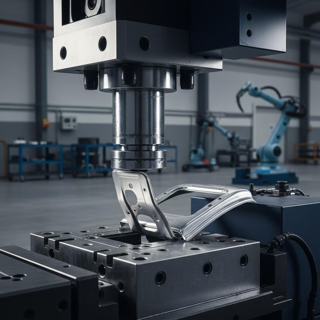
Ever wondered how flat sheets of metal transform into the complex automotive panels, aerospace brackets, or precision electronics enclosures you see every day? The answer lies in a critical manufacturing tool that most engineers consider the backbone of metal forming: the sheet metal die.
A sheet metal die is a precision tool designed to convert flat metal sheets or coils into specific three-dimensional shapes through controlled force and carefully engineered tooling. According to Tenral's technical documentation, the die functions as the core element in the stamping process, with its design and manufacturing directly affecting product quality and production efficiency.
The Anatomy of a Sheet Metal Die System
Think of a metal punch and die working together like a perfectly synchronized dance. The die—often called the female component—contains the cavity or profile that defines the final shape. The punch, serving as the male component, applies force to push the material into that cavity. This partnership creates everything from simple washers to complex automotive body panels.
Understanding the core components helps you appreciate how these systems achieve such remarkable precision:
- Punch: The moving tool that applies force to shape or cut the material
- Die block: The stationary component containing the cavity that receives the punch
- Stripper plate: Removes the workpiece from the punch after each stroke
- Guide pins: Ensure precise alignment between upper and lower die halves
- Pilot pins: Position the sheet metal accurately for each operation
- Backing plates: Distribute force and prevent deflection during stamping
How Dies Transform Raw Material Into Precision Parts
The transformation process is surprisingly elegant. When a press brings the punch down into the die, the sheet metal experiences controlled deformation. Depending on the specific metal die configuration, this single action might cut, bend, draw, or perform multiple operations simultaneously.
What makes metal forming dies so effective is their ability to exceed the material's yield strength—the point where permanent deformation begins—while staying below fracture limits. This precise control enables manufacturers to produce parts with tolerances measured in hundredths of a millimeter, consistently, stroke after stroke.
Some specialized configurations, like die dimple tooling, create raised or recessed features for specific applications such as fastener clearance or structural reinforcement. These variations demonstrate how sheet metal dies adapt to virtually any manufacturing challenge.
Why Manufacturing Depends on Die Technology
From automotive to aerospace, electronics to medical devices, sheet metal dies enable mass production of consistent, high-tolerance components that would be impossible to achieve economically through other methods. Consider this: a well-designed progressive die can produce hundreds of precision parts per minute, each one identical to the last.
The stakes are high. As noted by industry experts at Ferro-Tic, the partnership of dies and punches hinges on alignment, material behavior, and tool geometry—balancing force, precision, and material science to transform raw stock into functional designs.
Whether you're sourcing tooling for a new product launch or optimizing an existing production line, understanding these fundamentals positions you to make smarter decisions about die selection, design, and maintenance. The following sections will reveal the specialized knowledge that separates successful die implementations from costly mistakes.
Types of Stamping Dies and When to Use Each
Choosing the right stamping die can feel overwhelming when you're facing a wall of technical specifications and conflicting recommendations. Here's the truth most suppliers won't tell you: the "best" die type doesn't exist in isolation—it depends entirely on your specific production needs, part geometry, and budget constraints.
Understanding the types of stamping dies available transforms you from a passive buyer into an informed decision-maker. Let's break down the four primary categories and reveal when each one makes strategic sense for your operation.
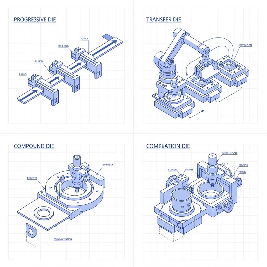
Progressive Dies for High-Volume Production
Imagine an assembly line compressed into a single tool. That's essentially what a progressive stamping die accomplishes. Metal strip feeds continuously through multiple stations, with each station performing a specific operation—punching, bending, drawing, or trimming—until the finished part exits at the end.
Why do automotive and electronics manufacturers favor progressive dies? Speed and consistency. A well-designed progressive die can produce hundreds of precision parts per minute while maintaining tight tolerances across millions of cycles. The continuous strip feeding eliminates the handling time between operations, making this approach exceptionally cost-effective for large production runs.
However, the initial tooling investment runs higher than simpler alternatives. You'll typically see progressive dies and stamping operations paired together when production volumes justify the upfront cost—usually starting around 10,000 parts annually, though this threshold varies based on part complexity.
Transfer Dies and Complex Part Geometries
What happens when your part is too large or complex for strip feeding? Transfer die stamping steps in as the flexible alternative. According to Worthy Hardware's technical comparison, this method works like an assembly line where individual blanks move mechanically or manually between stations, with each station contributing a specific operation to the final product.
The key advantage lies in flexibility. Transfer dies handle parts that require multiple orientations during forming—think deep-drawn housings, complex brackets, or components with features on multiple surfaces. This method can incorporate punching, bending, drawing, and trimming in a single production cycle while accommodating larger part sizes that would be impractical with progressive tooling.
The tradeoff? Higher operational complexity and potentially longer setup times. Operating a die stamping machine configured for transfer operations demands skilled technicians and precise die maintenance to ensure consistent quality. For intricate designs requiring frequent changeovers, factor in additional time and labor costs.
Compound vs Combination Dies Explained
These two forming dies often create confusion, but the distinction matters for your production planning.
Compound dies perform multiple cutting operations in a single stroke—typically blanking and piercing simultaneously. Picture punching out a washer in one press cycle: the outer diameter is blanked while the center hole is pierced at the same moment. This approach delivers exceptional flatness and concentricity because all operations occur while the material remains clamped in position.
Compound dies excel at producing high-precision flat parts where dimensional relationships between features are critical. However, they're limited to cutting operations—no forming, bending, or drawing.
Combination dies take things further by integrating both cutting and forming operations in the same stroke. You might blank a shape and immediately form a flange or emboss a feature, all before the press returns to top dead center. This approach reduces handling, improves alignment between cut and formed features, and can significantly boost throughput for medium-complexity parts.
The decision between these options often comes down to part requirements. Need a perfectly flat, precision-cut component? Compound dies deliver. Need to add dimensional features to that blank? Combination tooling handles both in one efficient stroke.
Stamping Die Selection Criteria That Actually Matter
Beyond understanding individual die types, successful engineers evaluate three interconnected factors:
- Production volume: Higher volumes generally favor progressive dies despite greater upfront investment. Lower volumes may justify simpler compound or transfer approaches.
- Part complexity: Deep draws, multiple orientations, and large sizes push toward transfer dies. Simpler geometries often work well with progressive or compound tooling.
- Tolerance requirements: Compound dies offer superior precision for flat parts. Progressive dies maintain excellent consistency across high volumes. Transfer dies provide flexibility but may require additional quality controls.
| Die Type | Best Application | Production Volume Suitability | Complexity Level | Typical Industries |
|---|---|---|---|---|
| Progressive Die | Multi-operation parts from continuous strip | High volume (10,000+ annually) | Medium to High | Automotive, Electronics, Appliances |
| Transfer Die | Large or complex parts requiring reorientation | Medium to High volume | High | Automotive body panels, HVAC, Heavy equipment |
| Compound Die | High-precision flat parts with multiple cut features | Low to Medium volume | Low to Medium | Precision instruments, Electrical components |
| Combination Die | Parts requiring cutting and forming in single stroke | Medium volume | Medium | Hardware, Consumer products, Fasteners |
Selecting the optimal stamping die involves balancing these factors against your budget and timeline constraints. The right choice reduces per-part costs, minimizes quality issues, and positions your production line for long-term success.
Of course, die type selection is only part of the equation. Specialized tooling like dimple dies addresses unique application requirements that standard configurations can't handle—a topic worth exploring if your designs include fastener clearance features or structural reinforcement elements.
Dimple Dies and Specialized Sheet Metal Tooling
You've selected your stamping die type and mapped out your production process. But what happens when your design calls for fastener clearance, weight reduction, or structural reinforcement that standard forming operations can't deliver? That's where dimple dies enter the picture—specialized tooling that solves problems most engineers encounter but rarely discuss openly.
A dimple die creates raised or recessed circular features in sheet metal, producing indentations that serve both functional and aesthetic purposes. Unlike conventional forming operations that reshape entire sections, dimpling dies target specific points on a panel, adding strength exactly where you need it without adding material weight.
Understanding Dimple Die Mechanics
Picture a controlled collision between two precisely machined surfaces. The male component pushes the sheet metal into the female cavity, stretching the material into a dome or dish shape. According to Woodward Fab's technical documentation, dimple dies are designed to reduce the weight of sheet metal while improving panel appearance—the overall weight decreases by removing excess material, which also helps in shaping the component.
Here's what makes this process particularly valuable: while a flat panel may feel flimsy and bend easily, adding a simple flare or dimple ensures years of rigidity. The dimpling action work-hardens the material at the deformation zone, creating a localized area of increased strength. This explains why sheet metal dimple die applications appear everywhere from hot rod builds to aerospace structures.
The mechanics differ from standard punching operations. A sheet metal dimple tool doesn't remove material—it redistributes it. The stretching action creates a raised rim around the dimple's edge, which contributes additional stiffness to the surrounding panel area. This redistribution is what separates dimple die sheet metal work from simple embossing or coining operations.
Selecting the Right Dimple Die Set Size
Sizing your dimple die kit correctly prevents cracked panels, torn material, and wasted production time. The selection process involves matching three critical variables: hole diameter, material thickness, and desired dimple depth.
Most dimple die sets range from 3/16 inch to 1-1/2 inch diameters, covering applications from small instrument panels to large structural components. But diameter alone doesn't determine success. You'll need to consider these key factors:
- Material thickness compatibility: Each die size handles a specific thickness range—typically 0.025" to 0.125" for most standard sets. Exceeding these limits risks cracking or incomplete forming.
- Dimple depth ratios: The relationship between hole diameter and dimple depth affects both appearance and structural performance. Deeper dimples provide more rigidity but require more forming force and may thin the material excessively.
- Die material hardness requirements: Heat-treated tool steel handles repeated use without deformation. As noted by TMR Customs, precision-machined dies crafted from high-quality heat-treated materials are built to last through repeated use without compromising performance.
- Press tonnage calculations: Thicker materials and larger diameters demand higher forming forces. Underestimate tonnage requirements, and you'll produce incomplete dimples. Overestimate, and you risk material tearing.
When working with a dimple die set for the first time, start with scrap material matching your production stock. This practice run reveals any sizing mismatches before they become costly problems on finished parts.
Common Dimple Die Applications in Fabrication
Where do dimple dies make the biggest impact? The applications span industries, but certain use cases demonstrate their value most clearly.
Automotive panels represent the classic dimple die application. Fabricators use them to create countersunk areas for flush-mounted fasteners on body panels, firewalls, and interior trim. The dimpled surface also provides grip for adhesives and sealants, improving bond strength in structural assemblies. Beyond function, dimpled panels have become an aesthetic signature in custom automotive builds—a visual cue that signals hand-crafted quality.
Aircraft skins rely on dimpling for a different reason: weight reduction without sacrificing strength. Every ounce matters in aviation, and dimpled panels provide the stiffness needed to resist aerodynamic loads while minimizing material mass. The reinforcement dimples also serve as countersinks for flush rivets, maintaining the smooth exterior surfaces critical for aerodynamic efficiency.
Custom fabrication projects benefit from the versatility dimple dies offer. Race car builders use them to strengthen floor pans and firewall panels. Industrial equipment manufacturers add dimples to sheet metal enclosures for improved rigidity. Even architectural metalwork incorporates dimpled patterns for decorative effect combined with structural benefits.
The versatility extends to material selection as well. Dimple dies work effectively with various metals, including steel, aluminum, and stainless steel—though specific die configurations and lubrication requirements vary based on material properties. Lubrication reduces friction and heat during the dimpling process, resulting in smoother operation and prolonged die life.
Understanding when and how to deploy these specialized tools separates competent fabricators from true experts. But tooling selection is only one piece of the puzzle—the engineering process behind die design determines whether your investment delivers consistent results or frustrating quality variations.
Die Design Process and Engineering Fundamentals
You've selected the right die type and understand specialized tooling options. But here's the uncomfortable truth most die suppliers won't tell you: the actual design process determines whether your tooling investment pays off or becomes an expensive lesson. According to Mekalite's comprehensive guide, the precision and quality of metal stamping die design are directly proportional to the quality of the final part—and have a direct consequence on production costs, tool service life, and production speed.
Getting the design right the first time saves both money and time. Getting it wrong? Expect costly rework, production delays, and parts that never quite meet specifications.
From Part Drawing to Die Concept
Every successful sheet metal stamping dies project starts with a fundamental question: can this part actually be stamped? Before investing in tooling, experienced engineers conduct a thorough feasibility analysis that examines the part geometry for potential manufacturing challenges.
What are they looking for? Complex patterns that might cause material flow problems. Sharp corners that could crack during forming. Deep draws that exceed the material's formability limits. Features that would require impractical tool geometries or excessive press tonnage. This initial checkpoint prevents you from discovering design flaws after you've already committed to expensive tooling.
Once feasibility is confirmed, the focus shifts to process planning. This phase determines how the metal forming dies will transform raw stock into finished parts. For progressive dies, engineers map out the sequence of operations—deciding which stations handle cutting, which perform forming, and how the strip advances between them. For simpler tooling like sheet metal punch dies, the planning addresses material orientation, nesting efficiency, and optimal blank dimensions.
The die concept emerges from this planning phase as a preliminary design that establishes the fundamental approach. Will the tool require a metal die punch for piercing operations? How will the stripper system function? Where will pilots locate the material? These decisions cascade through every subsequent design phase.
Strip Layout and Material Utilization
Here's where money gets saved or wasted—often in ways that aren't immediately obvious. Strip layout optimization determines how efficiently your metal stamping dies consume raw material. A poorly planned layout might achieve the same part quality as an optimized one, but it could waste 15-25% more material over a production run.
The layout specifies how the metal sheet moves through the die, detailing every cut, bend, and form in precise sequence. Engineers balance multiple competing priorities: minimizing scrap, maintaining stable strip feeding, ensuring adequate material for each forming operation, and creating space for pilot holes and carrier strips.
One critical consideration often overlooked: bypass notches in sheet metal stamping dies. These deliberate relief cuts prevent material interference as the strip advances through progressive stations. Without proper bypass notches, formed features can collide with subsequent die components, causing jams, tool damage, or part defects. Experienced designers anticipate these issues during layout development rather than discovering them during tryout.
Material utilization calculations inform the economic viability of your approach. If a redesigned part geometry allows a more efficient nest, the material savings over high-volume production can easily justify the additional engineering investment.
Simulation-Driven Die Development
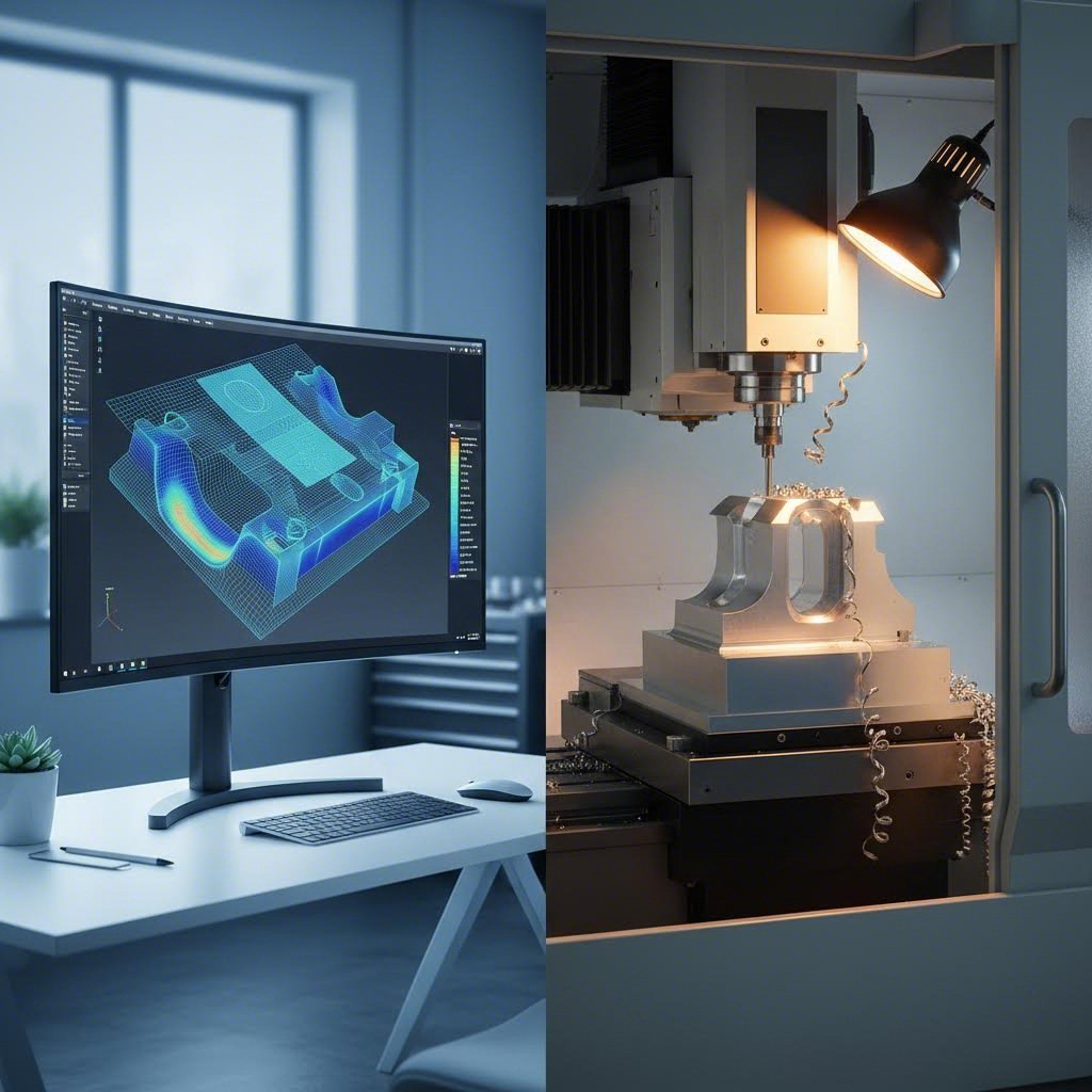
What if you could test your die design before cutting a single piece of steel? That's exactly what CAE simulation delivers—and it's transformed metal stamping die design from an art into a science.
Modern Finite Element Analysis (FEA) software creates virtual models of the entire forming process. These simulations calculate how sheet metal will stretch, thin, and flow during each operation. They predict where problems will occur before physical tooling exists.
According to ETA's technical guide on springback prevention, accurate prediction through simulation is the foundation for effective die compensation—drastically reducing the number of physical tryouts. The software identifies three critical failure modes:
- Springback: The elastic recovery that causes formed parts to deviate from intended dimensions. High-strength steels amplify this effect significantly due to their higher yield strength and the greater elastic energy stored during forming.
- Wrinkling: Compression-induced buckling that creates unwanted surface irregularities, particularly in deep draw operations where material flow isn't adequately controlled.
- Thinning: Excessive material stretching that weakens the part and can lead to splits or tears during forming or in service.
Simulation also addresses tolerance stackup—the cumulative effect of individual dimensional variations across multiple operations. Each station in a progressive die contributes its own variation. Without careful analysis, these small deviations compound into unacceptable final part dimensions.
The investment in simulation-driven development pays dividends in die longevity as well. By optimizing material flow and reducing localized stress concentrations, engineers extend tool life and reduce maintenance intervals.
Sequential Design Phases That Deliver Results
Successful metal stamping dies follow a structured development process. Skipping steps or rushing phases almost always costs more in the long run than doing it right initially. Here's the sequence that consistently produces reliable tooling:
- Part feasibility analysis: Evaluate the design for stampability, identifying features that may require modification or special tooling approaches.
- Process planning: Determine the optimal sequence of operations, material flow direction, and production method (progressive, transfer, or compound).
- Die concept development: Establish the fundamental tool architecture, including die type, station count, and critical functional elements.
- Detailed engineering: Create complete 3D models of all die components, specifying materials, tolerances, and surface treatments.
- Simulation validation: Run forming simulations to verify material behavior, identify potential defects, and optimize process parameters.
- Design for manufacturability review: Ensure all components can be produced efficiently and assembled correctly, with appropriate consideration for maintenance access.
This systematic approach reveals problems when they're cheapest to fix—on the computer screen rather than on the shop floor. The documentation generated through this process also serves as a reference guide for toolmakers and provides the baseline for future maintenance and modification decisions.
Of course, even the most sophisticated design process means nothing if you're working with the wrong materials. The next consideration—material selection and thickness compatibility—determines whether your beautifully engineered die performs as intended or struggles against the physical properties of your production stock.
Material Selection and Thickness Compatibility Guide
You've designed the perfect die and mapped out your production sequence. But here's a question that trips up even experienced engineers: does your sheet metal for stamping actually cooperate with your tooling? The answer depends on understanding how material properties directly influence die performance, wear rates, and part quality.
According to Talan Products' material selection guide, choosing the right metal affects everything from durability to manufacturability to cost. Let's explore what this means for your sheet metal stamping operations.
Steel Grades and Die Wear Considerations
Steel remains the workhorse of stamping sheet metal operations—and for good reason. It offers an excellent balance of strength, formability, and cost-effectiveness. But not all steels behave the same way under your punch and die.
Mild steel and carbon steel represent the most forgiving materials for stamping operations. Their moderate yield strength and good ductility allow for aggressive forming without excessive springback. Steel stamping dies working with these materials typically experience predictable wear patterns and longer service intervals. Low-carbon grades (below 0.25% carbon) form easily but offer limited strength, while medium-carbon grades (0.25-0.60% carbon) provide better strength with slightly reduced formability.
High-Strength Low-Alloy (HSLA) steel changes the equation significantly. These materials deliver higher strength with less weight—making them popular in automotive and structural applications. However, the increased yield strength translates directly to higher forming forces, accelerated tool wear, and more pronounced springback. Your sheet metal punch and die clearances need adjustment, and you'll likely need more frequent sharpening intervals.
Stainless steel presents unique challenges that catch many engineers off guard. The material work-hardens rapidly during forming, meaning each stroke increases the hardness of the stamped area. This work hardening rate demands careful attention to die clearances and forming sequences. Additionally, stainless exhibits significant springback—the elastic recovery that causes formed parts to deviate from intended dimensions. Successful stainless stamping often requires die compensation, where tooling is deliberately over-formed to account for this recovery.
Aluminum Stamping Challenges and Solutions
When weight reduction matters, aluminum alloys step into the spotlight. They offer excellent strength-to-weight ratios and natural corrosion resistance. But aluminum also introduces challenges that can frustrate unprepared fabricators.
Galling represents the primary concern with aluminum stamping. This adhesive wear phenomenon occurs when aluminum transfers onto die surfaces, creating built-up deposits that scratch subsequent parts and accelerate tool degradation. The solution? Proper lubrication, surface treatments on die components, and sometimes specialized die materials like bronze alloys or carbide inserts in high-wear areas.
Common aluminum grades for stamping include 1100 (pure aluminum, excellent formability), 3003 (general-purpose with good corrosion resistance), 5052 (higher strength with good formability), and 6061 (heat-treatable with excellent mechanical properties). Each grade responds differently to forming operations, and your die design should account for these variations.
Aluminum's lower yield strength compared to steel might seem like an advantage—and it does reduce tonnage requirements. However, the material's sensitivity to surface defects and its tendency toward orange peel texturing during deep draws demand careful attention to die surface finish and forming speeds.
Thickness Ranges and Clearance Calculations
Here's where the technical details directly impact your production quality. Punch-to-die clearance—the space between cutting edges—determines edge quality, burr height, and tool life. According to Dayton Lamina's extensive research, optimizing die clearance is one of the most important steps to punching success.
The traditional rule of thumb specified 5% of stock thickness per side for clearance. However, Dayton's testing across more than 10,000 clearance tests revealed that significantly increased clearances—reaching as high as 28% per side depending on material—can actually reduce burr height, increase punch life, and improve hole quality.
Why does this matter? A too-tight clearance causes the upper and lower fracture planes to miss each other during punching, creating secondary cracks and excessive stripping forces. The material grabs the punch during withdrawal, accelerating wear on both punch and die button. Proper clearance produces a slug with consistent burnished land (approximately one-third of material thickness) and an even fracture plane.
Material thickness also directly affects tonnage requirements. Thicker stock demands proportionally higher forming forces, which influences press selection and die component sizing. Exceeding your die's tonnage capacity leads to premature wear, component deflection, and dimensional inconsistencies in stamped sheet metal parts.
Material Selection Reference Guide
The following table summarizes key considerations across common stamping materials:
| Material Type | Typical Thickness Range | Key Challenges | Die Material Recommendations |
|---|---|---|---|
| Mild Steel / Carbon Steel | 0.015" - 0.250" | Moderate wear; scale on hot-rolled grades | D2 tool steel; carbide inserts for high volume |
| HSLA Steel | 0.020" - 0.187" | High forming forces; accelerated wear; significant springback | M2 or M4 high-speed steel; carbide for cutting edges |
| Stainless Steel | 0.010" - 0.125" | Work hardening; springback; galling potential | A2 or D2 with surface treatments; bronze alloy components |
| Aluminum Alloys | 0.020" - 0.190" | Galling; surface sensitivity; orange peel texturing | Bronze alloys; carbide with polished surfaces; proper coatings |
| Copper / Brass | 0.010" - 0.125" | Work hardening (copper); chip welding; burr formation | Carbide inserts; D2 tool steel with high polish |
Copper and brass deserve special mention for electrical and thermal applications. These materials offer excellent conductivity but present their own forming challenges. Copper work-hardens during forming, requiring careful process planning for multi-stage operations. Brass machines and forms more readily but can produce problematic burrs without proper clearances.
Understanding these material-specific behaviors transforms your approach to die specification. Rather than applying one-size-fits-all parameters, you'll tailor clearances, select appropriate die materials, and anticipate maintenance requirements based on your production stock's actual properties.
Of course, even perfect material selection doesn't eliminate the need for ongoing tooling care. The next consideration—die maintenance and lifespan optimization—determines whether your investment delivers years of reliable production or disappointing premature failures.
Die Maintenance and Lifespan Optimization
You've invested significantly in quality tooling and selected the right materials for your application. But here's what separates profitable stamping operations from frustrating ones: how well you maintain that investment after it hits the production floor. According to Phoenix Group's analysis, a poorly defined die shop management system—including die maintenance and repair processes—can dramatically decrease press line productivity and increase costs.
The stakes are higher than most engineers realize. Poor die stamping maintenance causes quality defects during production, drives up sorting costs, increases the likelihood of shipping defective parts, and risks expensive forced containments. Let's explore the maintenance strategies that keep your stamp dies performing at peak efficiency.
Preventive Maintenance Schedules That Extend Die Life
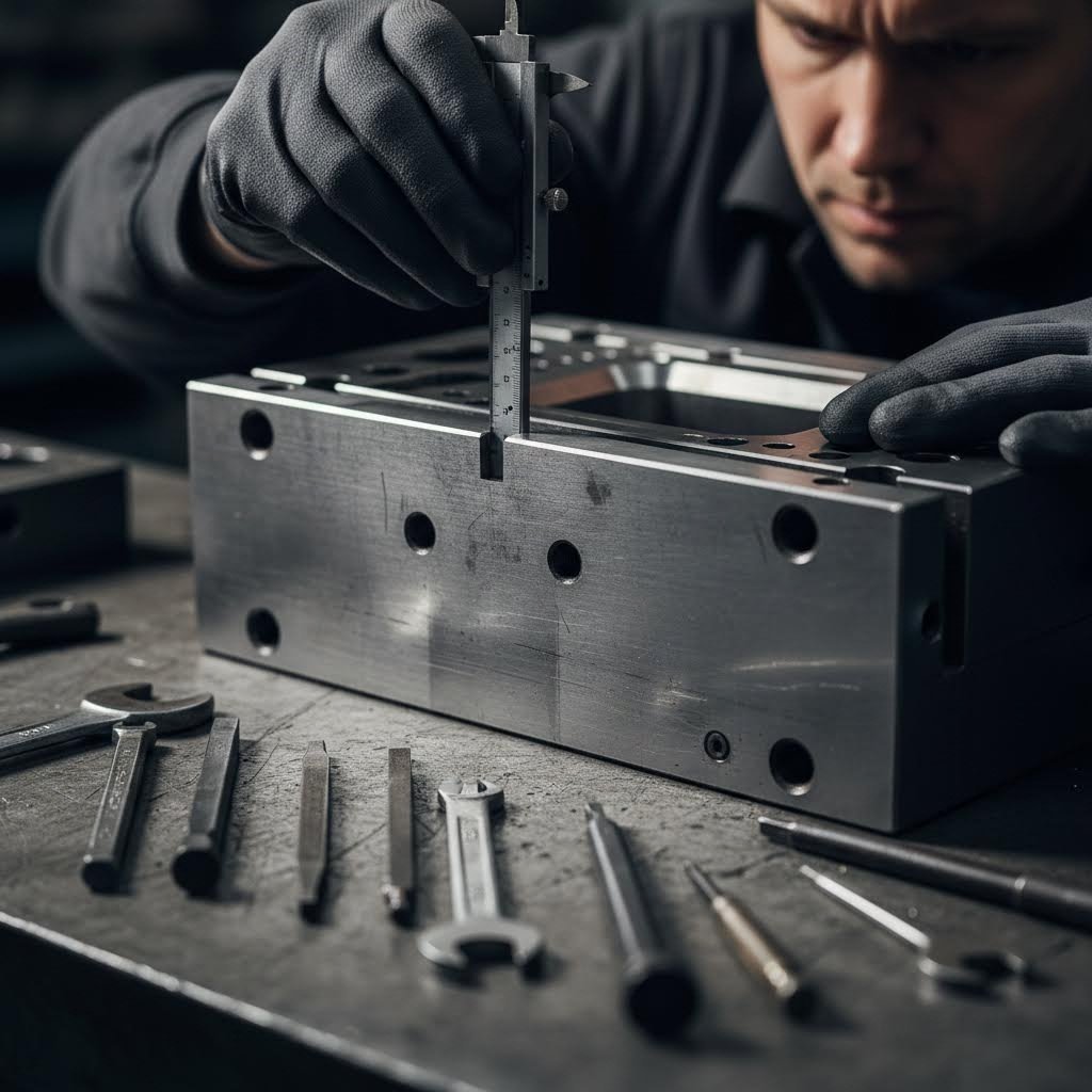
Think of preventive maintenance as insurance for your tooling investment. Rather than waiting for problems to halt production, systematic inspections identify wear before it affects part quality. But what exactly should you be checking—and how often?
According to Manor Tool's maintenance protocols, high-quality maintenance programs that use predictive systems and preventive maintenance help resolve potential problems before they significantly affect production. The cutting sections and punch edges of a die stamp wear down over time through normal use, resulting in potential errors in the parts produced.
Effective maintenance programs track these critical checkpoints at regular intervals:
- Cutting edge condition: Inspect for chipping, rounding, or buildup that affects edge quality and burr formation
- Guide pin wear: Check for scoring, galling, or excessive clearance that compromises alignment
- Spring fatigue: Verify proper pressure and replace springs showing reduced force or permanent set
- Alignment verification: Confirm punch-to-die alignment remains within specification across all stations
- Surface finish degradation: Examine forming surfaces for scratches, pitting, or material transfer that affects part quality
Sharpening intervals depend on material type, production volume, and part complexity. Most die and stamping operations schedule sharpening based on hit counts—typically every 50,000 to 150,000 strokes for standard steel stamping. Harder materials or tighter tolerances demand more frequent attention. Periodically employing a grinding wheel to sharpen the die stamped edges prevents wear conditions from impacting manufacturing operations.
Recognizing Wear Patterns Before Quality Suffers
Your parts tell a story about die condition—if you know how to read it. Experienced technicians recognize early warning signs that indicate maintenance is due before quality problems reach customers.
Watch for these indicators during regular production monitoring:
- Increasing burr height: Signals cutting edge wear or clearance changes requiring sharpening or adjustment
- Dimensional drift: Gradual changes in part dimensions often indicate guide wear or alignment issues
- Surface defects: Scratches, galling marks, or orange peel texturing suggest forming surface degradation
- Inconsistent forming depth: May indicate spring fatigue, press timing issues, or wear in forming components
- Increased stripping forces: Often caused by punch wear, inadequate lubrication, or clearance problems
A variety die and stamping operation benefits from detailed inspection protocols. Regular cleaning and inspection provide opportunities to detect and prevent issues that may evolve into full-blown production problems. Look for galling, cracking, surface wear, or any areas that appear to be abnormal in the die's condition.
Documentation matters here. Work order systems allow organizations to document, track, prioritize, and schedule all die repair or maintenance activities. A completed work order should record what the agreed-upon die work was intended to accomplish and provide a means to track reoccurrences in the future.
When to Refurbish vs Replace Die Components
Every die component eventually reaches the end of its service life. The question isn't whether to replace—it's when replacement makes more economic sense than continued maintenance. Making this decision incorrectly wastes money in either direction.
Refurbishment makes sense when:
- Wear is within regrindable limits and original geometry can be restored
- Component cost significantly exceeds refurbishment cost
- Lead time for replacement exceeds production schedule demands
- The die set has substantial remaining production life
Replacement becomes necessary when:
- Wear exceeds regrind allowance or affects critical dimensions permanently
- Multiple refurbishment cycles have consumed available material
- Crack propagation threatens catastrophic failure
- Updated design requirements make original components obsolete
Adding shims to die sections may be necessary to ensure each die station maintains proper timing after sharpening operations remove material. When adding shims, consider the impact on overall die height, alignment, and timing relationships between stations.
Storage requirements also affect component longevity. Dies waiting for production runs need protection from corrosion, physical damage, and contamination. Climate-controlled storage, protective coatings, and proper support prevent degradation during idle periods. Handle dies carefully during transport—dropped tooling often suffers hidden damage that only appears during subsequent production runs.
Proper die maintenance isn't an expense—it's an investment that pays dividends through extended tool life, consistent part quality, and reduced unplanned downtime.
The most successful stamping operations treat maintenance as a strategic priority rather than a reactive necessity. By establishing systematic inspection schedules, training personnel to recognize early warning signs, and making informed refurbishment decisions, you protect your tooling investment while maintaining the production quality your customers expect.
Of course, maintenance represents just one component of total tooling costs. Understanding the full economic picture—including how initial die investment correlates with long-term production savings—positions you to make smarter procurement decisions from the start.
Cost Analysis and ROI Considerations for Die Investment
You've mastered die types, materials, and maintenance strategies. But here's the question that keeps procurement managers awake at night: how do you justify the upfront investment in custom metal stamping dies when cheaper alternatives seem available? The answer lies in understanding total cost of ownership—a calculation that reveals why the lowest quote often becomes the most expensive decision.
According to Jennison Corporation's cost analysis, tooling is the first influence on the price of metal stamping—not the material, not the labor. Understanding this relationship transforms how you evaluate stamping tool and die investments.
Understanding Die Investment Factors
What drives the price tag on a custom metal stamp die? Several interconnected factors determine whether you're looking at a $5,000 investment or one exceeding $100,000.
Complexity represents the primary cost driver. Simple blanking dies that cut basic shapes cost significantly less than progressive dies performing multiple operations across numerous stations. Each additional forming station, piercing operation, or precision feature adds engineering time, specialized components, and manufacturing complexity. Think of complexity as a multiplier that touches every aspect of tooling cost.
Size directly impacts material costs and machining time. Larger dies require more tool steel, bigger presses for manufacturing, and extended processing times. A sheet metal die press handling 24-inch parts demands substantially more investment than one producing 6-inch components—even when part complexity remains identical.
Material selection for die components affects both initial cost and long-term performance. Standard D2 tool steel serves many applications adequately, but high-volume production or abrasive materials may demand carbide inserts, special coatings, or premium alloys that increase upfront costs while extending service life.
Tolerance requirements create perhaps the most underestimated cost impact. As one industry veteran with 40 years of experience noted, customer-requested tolerances have consistently tightened—what used to be ±0.005 inch is now ±0.002 inch and sometimes even ±0.001 inch. Each tightening of tolerance demands more precise tooling, slower production speeds, or additional secondary operations.
Production volume expectations influence design decisions that affect long-term economics. Dies intended for millions of cycles require more robust construction, better materials, and enhanced wear resistance compared to tooling destined for shorter runs.
Calculating True Cost Per Part
Here's where the math gets interesting—and where many buyers make costly mistakes. The per-part cost formula isn't just about dividing die cost by volume. According to industry analysis, the true calculation follows this pattern: (Total production cost) = N × (Raw material cost) + N × (Hourly Cost) × (Cycle time per piece) / (Efficiency) + Tooling costs.
Consider this scenario: You receive two quotes for identical stamped parts. One supplier quotes $0.50 per piece, another quotes $5.00. Your first instinct? Someone's trying to overcharge. But both might be right—depending on volume assumptions, tooling amortization, and production efficiency factors hidden within those numbers.
The magic happens when fixed tooling costs spread across larger volumes. Make 1,000 parts, and that expensive die cost hits each part hard. Make 100,000 parts, and suddenly that tooling investment becomes almost invisible in your per-piece calculation. This relationship explains why volume commitments unlock pricing that seems almost magical—it's not magic, it's mathematics.
Metal stamping tooling typically reaches its economic sweet spot between 10,000 to 100,000+ pieces annually, though complexity affects this threshold significantly. Below that range, alternative processes like laser cutting might serve you better. Above it? You're in stamping's happy place where the economics truly shine.
Quality Tooling and Production Economics
The cheapest die rarely delivers the lowest total cost. This counterintuitive truth frustrates budget-focused buyers but rewards those who understand the complete economic picture.
Dies from quality manufacturers are guaranteed to 1,000,000+ strikes before needing maintenance to continue delivering the same quality parts. Do not try to cut costs on tooling and die design and manufacturing.
Quality metal stamping tooling impacts production economics through multiple channels:
- Scrap rates: Precision stamping minimizes material waste by ensuring each metal sheet or coil is used efficiently, resulting in cost savings and reduced environmental impact
- Secondary operations: Well-designed tooling often eliminates downstream processing—deburring, grinding, or rework—that budget dies require
- Production efficiency: Reliable dies run faster with fewer interruptions, maximizing press utilization and reducing labor costs per part
- Maintenance intervals: Premium materials and engineering extend time between service cycles, reducing both direct maintenance costs and production downtime
Total cost of ownership extends beyond purchase price to include maintenance, refurbishment, and eventual replacement. According to M&M Sales analysis, outdated or inadequate tooling can slow down production and result in a poor finished product—costing your company additional time, labor, and material.
One documented case study revealed that investing in better tooling enabled a manufacturer to shave 1,000 production hours, save $100,000 per batch, and achieve better tool life with increased machine uptime. The initial investment paid for itself many times over through operational improvements.
The dramatic potential for savings becomes clear when you consider the full picture: metal stamping can reduce part costs by 20% to 80% (or more) versus other sheet metal manufacturing processes. However, realizing these savings requires commitment to quality tooling and sustained partnership with capable suppliers.
Understanding these economics positions you to make smarter sourcing decisions. But knowing what to look for in a die supplier—and how to evaluate their capabilities—determines whether those economic benefits materialize in your actual production results.
Selecting the Right Die Manufacturer for Your Application
You understand die economics and recognize that quality tooling delivers superior long-term value. But here's the challenge that trips up even experienced procurement teams: how do you identify stamping die manufacturers capable of delivering on those promises? The difference between a reliable partner and a frustrating supplier often comes down to evaluation criteria most buyers overlook.
According to Group TTM's comprehensive guide, selecting the right automotive sheet metal stamping dies manufacturer requires a comprehensive evaluation of several key factors—going beyond simply comparing costs or proximity. Let's explore what separates exceptional metal stamping die manufacturers from the rest.
Evaluating Die Manufacturer Engineering Capabilities
Technical expertise forms the foundation of every successful die partnership. But what specific capabilities should you investigate before committing to a stamping dies manufacturer?
Advanced tooling technology signals a manufacturer's commitment to precision and repeatability. Look for investments in CNC machining, wire EDM, and integrated CAD/CAM systems—these tools ensure the highest level of accuracy across complex die geometries. A die-stamping machine producing automotive-grade components demands tooling manufactured with equally exacting standards.
Simulation capabilities reveal whether a manufacturer can identify problems before cutting steel. CAE (Computer-Aided Engineering) simulation predicts material flow, springback compensation requirements, and potential forming defects during the design phase. This capability dramatically reduces physical tryout iterations and accelerates time-to-production. Manufacturers lacking simulation expertise often rely on trial-and-error approaches that extend timelines and increase costs.
Material expertise matters more than most buyers realize. Your automotive stamping dies may need to handle high-strength steels, aluminum alloys, or specialty metals—each presenting unique forming challenges. Capable manufacturers demonstrate experience across material types and can advise on optimal approaches for your specific application.
Use these criteria when evaluating potential suppliers:
- Design software and simulation tools: Verify CAE/FEA capabilities for forming simulation and springback prediction
- Manufacturing equipment: Confirm CNC machining, wire EDM, and precision grinding capabilities
- Material handling range: Assess experience with your specific material types and thickness ranges
- Engineering team depth: Evaluate the availability of dedicated design engineers for collaborative development
- Tryout and validation facilities: Confirm on-site press capabilities for die testing and optimization
Why Certification Standards Matter for Quality
Certifications aren't just wall decorations—they represent documented commitment to systematic quality processes. For demanding applications, these standards separate reliable partners from risky choices.
IATF 16949 certification stands as the gold standard for automotive supply chain manufacturers. This certification, according to Core Business Solutions, demands precise documentation, strong process control, and a disciplined approach to corrective action. Organizations in the automotive supply chain face some of the strictest quality expectations in manufacturing—and IATF 16949 compliance demonstrates capability to meet those expectations.
What does this certification actually verify? Several critical process elements:
- Documented procedures: Every manufacturing step follows written protocols that match actual practices
- Corrective action effectiveness: Problems get resolved through root cause analysis with verified long-term solutions
- Training and competency records: Personnel demonstrate documented qualifications for their roles
- Traceability systems: Materials, processes, and inspections link together for complete production history
- Leadership accountability: Management reviews and continuous improvement drive systematic quality advancement
ISO 9001 certification provides baseline quality management system verification, while IATF 16949 builds upon these requirements with automotive-specific additions. For non-automotive applications, ISO 9001 may suffice—but for OEM-destined components, IATF certification becomes virtually mandatory.
Why does this matter for your custom metal stamping die project? Certified manufacturers maintain the process discipline that prevents the common failures plaguing less rigorous operations: inconsistent dimensions, undocumented changes, and quality problems that resurface after apparent correction.
From Prototype to Production Volume
The journey from concept to full-scale production reveals a manufacturer's true capabilities. Evaluate how potential partners handle this critical transition.
Prototyping speed indicates engineering efficiency and resource availability. When design validation demands rapid iteration, slow prototyping creates costly delays. Leading manufacturers deliver prototype tooling in compressed timeframes—some achieving initial samples in as few as 5 days for straightforward applications. This rapid prototyping capability, combined with advanced CAE simulation, enables Shaoyi to help customers validate designs quickly while maintaining the precision that automotive applications demand.
First-pass approval rates reveal process maturity more clearly than any sales pitch. A manufacturer achieving 93% or higher first-pass approval demonstrates the engineering discipline and quality systems that prevent costly rework cycles. Shaoyi's documented 93% first-pass approval rate reflects their commitment to simulation-driven development and rigorous quality protocols—exactly what IATF 16949 certification verifies.
Production capacity and flexibility determine whether your supplier can scale with your needs. Assess current capacity utilization, equipment redundancy, and the manufacturer's track record accommodating volume changes or rush orders. A flexible partner adapts to your changing requirements without compromising quality or lead times.
Consider these additional evaluation factors:
- Communication responsiveness: How quickly do they respond to inquiries and provide project updates?
- Design collaboration approach: Will engineering staff participate in design reviews and offer optimization suggestions?
- Long-term partnership potential: Does the manufacturer invest in understanding your business and growth trajectory?
- Maintenance and support: What post-delivery support do they provide for die maintenance and modifications?
- Cost transparency: Do quotes clearly itemize components, or hide costs that surface later?
Effective communication extends throughout the project lifecycle. Choose manufacturers who provide regular progress updates, proactively address potential issues, and remain accessible for questions. Good customer service includes support throughout the entire lifecycle of the dies—including maintenance guidance and potential modifications as your production needs evolve.
For projects requiring certified quality and comprehensive engineering expertise, Shaoyi's automotive stamping die solutions demonstrate these evaluation criteria in action—combining IATF 16949 certification, advanced CAE simulation capabilities, and rapid prototyping with high-volume manufacturing capacity tailored to OEM standards.
Finding the right manufacturer solves only part of the equation. The final piece—building a complete die selection strategy that matches tooling decisions to your specific production requirements—brings together everything you've learned into an actionable framework.
Building Your Complete Die Selection Strategy
You've absorbed the technical knowledge—die types, material considerations, design fundamentals, and supplier evaluation criteria. But here's what separates engineers who make excellent tooling decisions from those who learn expensive lessons: the ability to synthesize this information into a clear, actionable framework. Let's transform everything you've learned into a decision-making system that works.
According to research on manufacturing process selection, evaluation of various factors—including cost, quality requirements, production volume, material properties, and equipment capabilities—is necessary when choosing a manufacturing process. Finding the best strategy requires careful analysis and consideration. Your sheet metal punch and die set investment deserves exactly this systematic approach.
Building Your Die Selection Decision Framework
Imagine standing at the start of a new stamping project. Where do you begin? Rather than jumping straight to supplier quotes, work through this sequential decision framework that connects every concept we've explored:
- Analyze part geometry and complexity: Examine your component for deep draws, multiple orientations, and feature density. Complex geometries requiring reorientation point toward transfer dies; simpler, repetitive features suit progressive or compound tooling.
- Establish production volume requirements: Define your annual volume expectations and project lifecycle. High-volume production (10,000+ annually) typically justifies progressive die investment, while lower volumes may favor compound or combination approaches with reduced upfront costs.
- Define tolerance specifications: Identify critical dimensions and acceptable variation ranges. Tighter tolerances demand precision tooling, simulation-driven development, and potentially specialized sheet metal punches and dies with enhanced wear resistance.
- Evaluate material properties: Match your sheet metal characteristics—yield strength, work hardening rate, and thickness—to appropriate die materials and clearance calculations. Stainless steel springback differs dramatically from mild steel behavior.
- Calculate total cost of ownership: Factor maintenance intervals, expected tool life, and production efficiency into your economic analysis. The lowest quote rarely delivers the lowest total cost.
- Assess supplier capabilities: Verify engineering expertise, certification standards, and production capacity against your project requirements. A punch flare of quality issues often traces back to inadequate supplier evaluation.
Matching Die Type to Production Requirements
Your answers to these framework questions directly map to tooling decisions. Here's how the connections work:
For high-volume, moderate-complexity parts: Progressive dies deliver the best economics. The upfront investment spreads across massive production runs, and continuous strip feeding maximizes throughput. Your metal stamping die sets should include robust wear components sized for extended service intervals.
For complex geometries with multiple orientations: Transfer dies handle what progressive tooling cannot. Larger parts, deep draws, and features requiring repositioning demand this flexible approach—though operational complexity increases accordingly.
For precision flat parts with critical feature relationships: Compound dies excel at maintaining concentricity and dimensional relationships between cut features. The single-stroke approach eliminates alignment variations between operations.
For specialized applications requiring dimples or reinforcement: Dimple die sets address fastener clearance, weight reduction, and structural stiffening needs that standard forming operations cannot achieve. Consider these as complementary tooling rather than primary forming solutions.
Your metal die set selection ultimately balances these factors against budget constraints. The framework prevents the common mistake of choosing based on a single variable while ignoring interconnected considerations that determine long-term success.
Taking the Next Step in Your Tooling Project
Where you go from here depends on your current position in the sourcing journey. Consider these pathways based on your situation:
If you're in early design phases: Engage potential die manufacturers during product development—not after drawings are finalized. Collaborative design-for-manufacturability reviews identify opportunities to simplify tooling requirements and reduce costs before commitments are made.
If you have defined specifications: Request detailed quotations from multiple qualified suppliers. Compare not just pricing but engineering approaches, simulation capabilities, and proposed maintenance programs. The right metal stamping die sets deliver value through their entire lifecycle, not just at purchase.
If you're optimizing existing production: Evaluate current tooling performance against the maintenance and material considerations we've discussed. Sometimes incremental improvements—better die materials, optimized clearances, or enhanced maintenance protocols—deliver dramatic quality and cost improvements without complete tooling replacement.
For projects requiring certified quality and comprehensive engineering expertise, exploring manufacturers with demonstrated capabilities makes sense. Shaoyi's automotive stamping die solutions combine IATF 16949 certification, advanced CAE simulation, and rapid prototyping capabilities—the exact evaluation criteria we've established as essential for reliable die partnerships.
The secrets engineers rarely share aren't actually secrets—they're systematic approaches to tooling decisions that separate successful projects from frustrating ones. Apply this framework, and you'll make informed choices that deliver production excellence for years to come.
Frequently Asked Questions About Sheet Metal Dies
1. What is a die in sheet metal?
A sheet metal die is a precision tool that transforms flat metal sheets into three-dimensional components through controlled force. It consists of a female component (the die block with a cavity) working in tandem with a male component (the punch) to cut, bend, draw, or form metal. Dies are essential in manufacturing sectors from automotive to aerospace, enabling mass production of consistent, high-tolerance parts that would be impossible to achieve economically through other methods.
2. How much does a metal stamping die cost?
Metal stamping die costs range from $500 to over $100,000 depending on complexity, size, material requirements, tolerance specifications, and expected production volume. Progressive dies for high-volume automotive applications require greater investment than simple blanking dies. However, quality tooling often delivers lower total cost of ownership through reduced scrap rates, fewer secondary operations, and extended service life—sometimes exceeding 1,000,000 strikes before maintenance.
3. What is the purpose of a die in manufacturing?
A die serves as a specialized machine tool to cut and form material into specific shapes or profiles. In sheet metal stamping, dies work with presses to transform flat stock into precision components through operations including blanking, piercing, bending, and drawing. Dies enable manufacturers to produce hundreds of identical parts per minute with tolerances measured in hundredths of a millimeter, making them indispensable for high-volume production in automotive, electronics, and aerospace industries.
4. What are the different types of stamping dies and when should each be used?
The four primary stamping die types serve different applications: Progressive dies excel at high-volume production (10,000+ annually) with multi-operation parts from continuous strip. Transfer dies handle large or complex parts requiring reorientation between stations. Compound dies deliver superior precision for flat parts with multiple cut features in a single stroke. Combination dies integrate both cutting and forming operations simultaneously, ideal for medium-complexity parts requiring both processes.
5. How do I select the right die manufacturer for my project?
Evaluate die manufacturers based on engineering capabilities (CAE simulation, CNC machining), quality certifications (IATF 16949 for automotive applications), prototyping speed, and first-pass approval rates. Look for manufacturers demonstrating collaborative design approaches, transparent cost structures, and comprehensive post-delivery support. Certified manufacturers like Shaoyi combine advanced simulation capabilities with rapid prototyping and high-volume manufacturing capacity tailored to OEM standards.