 Small batches, high standards. Our rapid prototyping service makes validation faster and easier —

Rotary Cam Vs Aerial Cam: Which One Destroys Your Die First?
Why Your Cam Selection Makes or Breaks Die Performance
Imagine running a high-volume stamping operation when suddenly your cam mechanism fails mid-production. The press stops. Parts pile up. And your maintenance team scrambles to diagnose whether it's a design flaw or simply the wrong cam type for the job. Sound familiar?
When comparing rotary cam vs aerial cam systems, the stakes couldn't be higher. The wrong choice doesn't just cause inconvenience—it triggers a cascade of production delays, quality defects, and expensive retooling that can cost tens of thousands of dollars per incident.
The Hidden Cost of Wrong Cam Selection
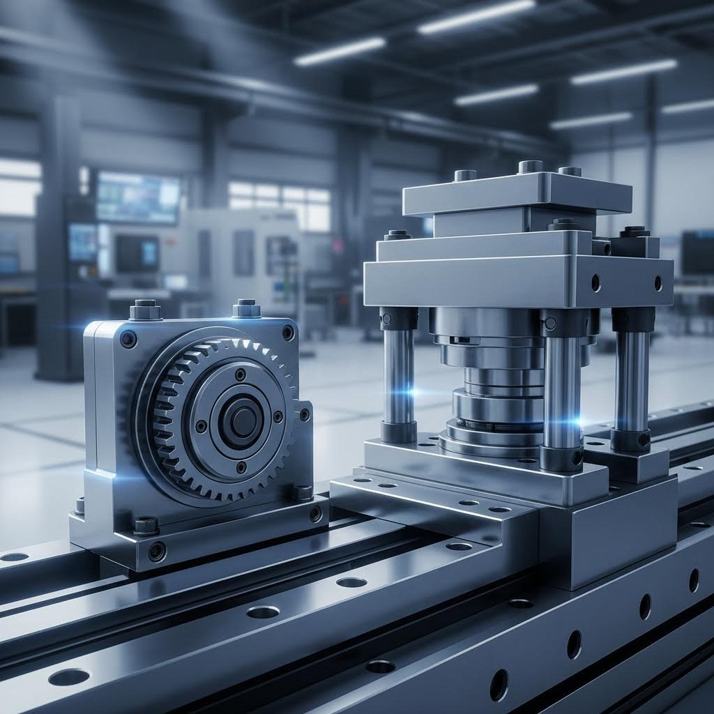
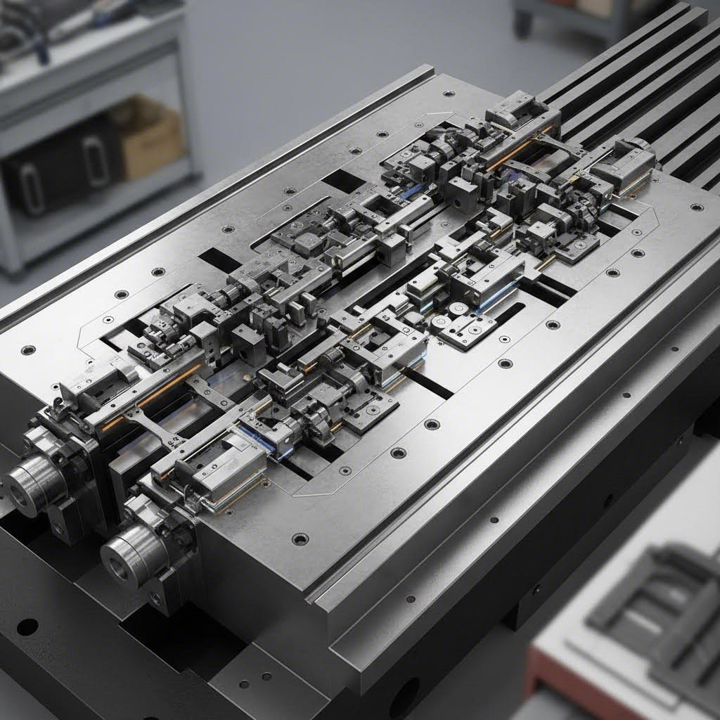
So what is a cam, and what does a cam do in stamping operations? At its core, a cam mechanically transfers vertical ram motion and force into horizontal or semihorizontal motion and force. This conversion is essential for cutting, forming, and piercing operations where precision alignment is critical. According to The Fabricator, cams must have excellent guidance systems and be designed to withstand natural wear and tear over thousands—even millions—of cycles.
Here's where many die designers stumble. They select a cam type based on initial cost or familiarity rather than application requirements. The result? Premature wear, thermal expansion issues, and cam slides that freeze up during production. Each camshaft lobe profile and cam actuation method has specific performance characteristics that must match your operational demands.
Two Mechanisms, Two Different Engineering Philosophies
Understanding the fundamental differences between these two type cam mechanisms is essential:
- Rotary Cams: These systems use circular motion to drive cam actuation, converting rotation into linear movement through precisely engineered cam design profiles. They excel in compact spaces and continuous operations.
- Aerial Cams: Unlike standard configurations, aerial cams mount the moving slide assembly on the top die shoe rather than the bottom. This positioning allows the entire cam slide to travel upward with the ram without interfering with transfer fingers and systems—enabling hole piercing at virtually any angle.
This comparison provides manufacturer-agnostic guidance based solely on your application requirements. You'll discover a practical decision-making framework that helps you match the right cam mechanism to your specific die operations—before costly mistakes happen.
Our Evaluation Criteria for Cam Mechanism Comparison
How do you objectively compare two fundamentally different cam designs? You need a systematic framework that eliminates guesswork and focuses on measurable performance factors. When evaluating rotary cam vs aerial cam options, we applied a methodology grounded in real-world stamping requirements rather than theoretical ideals.
Five Factors That Determine Cam Success
Every cam and follower mechanism must perform reliably under demanding production conditions. Research published in Mechanism and Machine Theory demonstrates that the acceptability of cam-follower system performance lies in its dynamic response testing—specifically displacement, velocity, acceleration, and jerk measurements. Building on these principles, we identified five critical evaluation factors:
- Force Capacity: The maximum horizontal force the cam equipment can generate and sustain throughout its operational cycle. This determines whether your cam parts can handle heavy-gauge materials and demanding forming operations.
- Motion Profile Accuracy: How precisely the cam translates vertical press motion into horizontal slide movement. According to cam optimization research, the matching between actual response and theoretical predictions depends on manufacturing precision and proper cam design parameters.
- Installation Footprint: The physical space required within your die assembly. Compact designs allow greater flexibility in complex die configurations, while larger footprints may offer other advantages.
- Maintenance Requirements: Accessibility for inspection, lubrication, and component replacement. Cams withstand friction and high force over millions of cycles, making maintenance access a critical long-term consideration.
- Application Suitability: How well each cam type matches specific die operations, production volumes, and material requirements. What do cams do best in your particular camshaft application scenario?
How We Evaluated Each Cam Type
Our evaluation approach recognizes that neither cam type holds absolute superiority. Rankings shift based on your specific use case. A rotary cam that excels in a high-speed progressive die might underperform in a large transfer die requiring maximum lateral force.
Technical specifications from manufacturer catalogs informed our comparison wherever available. We also referenced peer-reviewed engineering research on cam-follower dynamics to validate performance characteristics. This ensures our recommendations reflect both laboratory-tested principles and practical shop-floor realities.
With these evaluation criteria established, let's examine how rotary cams perform across each factor in precision die applications.
Rotary Cam Mechanisms for Precision Die Applications
Picture a perfectly synchronized dance between circular motion and linear precision. That's exactly what happens inside a rotary cam system every time your press cycles. This rotation mechanism transforms the continuous spin of a cam gear into the controlled horizontal movement your die operations demand—all within a remarkably compact footprint.
But how does this conversion actually work? And more importantly, when does a rotary cam outperform its aerial counterpart? Let's break down the mechanics and applications that make rotary cams the preferred choice for specific stamping scenarios.
How Rotary Cams Convert Motion
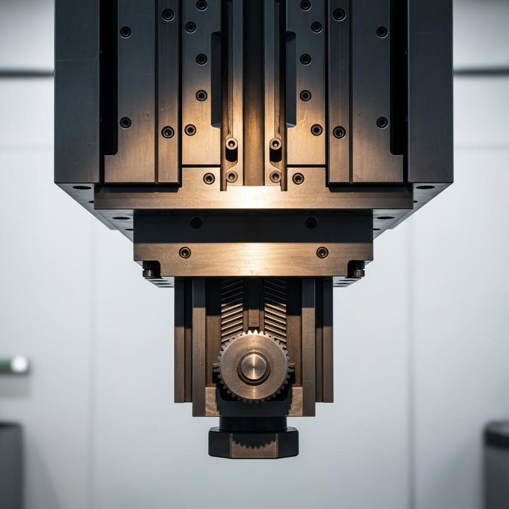
The fundamental principle behind rotary cam operation mirrors what you'll find in any cam and follower mechanism: converting rotational input into linear output with precise control. When a rotating motor drives the cam, its specially contoured surface—the cam lobe—makes contact with the follower, pushing the slide assembly along a predetermined path.
Here's where rotary cams distinguish themselves. Unlike mechanisms that rely on the press ram's vertical stroke for activation, rotary cams maintain their own independent rotation. This means:
- Continuous force application: The cam lobe delivers consistent pressure throughout its rotation cycle, eliminating the force variations that can occur with stroke-dependent systems.
- Predictable motion profiles: Because the cam profile geometry directly controls follower displacement, engineers can design precise velocity and acceleration curves. Research confirms that cam profile design determines the motion path, speed, and positioning accuracy of the follower.
- Smooth transitions: The circular nature of the rotation mechanism produces gradual engagement and disengagement, reducing shock loads on die components.
Think of lobe symmetry camshaft design principles applied to die operations. Just as automotive camshafts require precisely ground lobes for optimal valve timing, rotary cams in stamping dies demand equally precise profiles for consistent part quality.
Where Rotary Cams Excel in Die Operations
Rotary cams shine brightest in applications where space constraints meet high-cycle demands. Progressive dies represent their natural habitat. According to industry analysis from The Fabricator, when cam forming or piercing is required in progressive tooling, the cam and driver configuration significantly impacts die layout. Rotary cams often require less real estate than alternative designs, freeing valuable die space for additional forming stations.
Consider these typical rotary cam applications:
- High-speed progressive dies: Where cycle rates exceed 60 strokes per minute and consistent cam action prevents timing-related defects
- Compact die configurations: When multiple cam operations must fit within tight die boundaries
- Continuous production runs: Operations demanding millions of cycles with minimal variation in cam performance
- Precision forming operations: Applications where the smooth motion profile of rotary actuation prevents material cracking or springback issues
Pros of Rotary Cam Systems
- Space efficiency: Compact design allows integration into dies where footprint is limited
- Consistent force delivery: Uniform pressure application throughout the rotation cycle improves part quality
- High-speed capability: Independent rotation suits rapid cycling without sacrificing precision
- Smooth operation: Gradual cam lobe engagement reduces shock and extends component life
- Design flexibility: Custom cam profiles accommodate complex motion requirements
Cons of Rotary Cam Systems
- Force capacity limitations: May not match aerial cams for extreme lateral force requirements in heavy-gauge applications
- Maintenance accessibility: Compact integration can complicate inspection and component replacement
- Initial complexity: Requires precise timing coordination with press cycle, adding design considerations
- Heat generation: Continuous rotation in high-speed applications demands robust lubrication systems to manage thermal buildup
The cam gear and follower interaction in rotary systems benefits from advances in material science. Modern designs incorporate hardened steel components and ceramic coatings that significantly improve wear resistance—critical when your die must deliver consistent performance across extended production campaigns.
Understanding these rotary cam characteristics provides half the comparison picture. But what happens when your application demands maximum force capacity and easier maintenance access? That's where aerial cam architecture enters the conversation.
Aerial Cam Systems for Heavy-Duty Stamping Operations
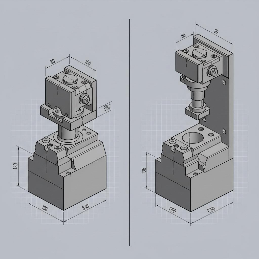
What if your stamping operation demands raw power over compact elegance? When rotary cams hit their force limits, aerial cam systems step in to handle the heavy lifting. These mechanisms—sometimes called die-mount or wide cams—take a fundamentally different approach to converting press motion into horizontal force.
Imagine mounting your entire cam slide assembly on the upper die shoe instead of the lower. That single configuration change unlocks capabilities that rotary designs simply cannot match in certain applications. Let's explore what makes aerial cams the go-to choice for demanding stamping scenarios.
Understanding Aerial Cam Architecture
The defining characteristic of an aerial cam lies in its vertical mounting configuration. Unlike rotary cams that rely on independent rotation, aerial cams harness the press ram's vertical stroke directly. The cam and follower assembly travels upward with the ram during the press cycle, creating a unique mechanical advantage.
Here's how this architecture differs from rotary designs:
- Top-die mounting: The moving slide assembly attaches to the upper die shoe, traveling with the ram throughout each stroke. This arm rotation pattern keeps the mechanism clear of lower die components and transfer systems.
- Driver engagement: A stationary driver mounted on the lower die shoe engages the aerial cam during the downstroke, converting vertical force into horizontal slide movement.
- Stroke-dependent activation: Unlike continuously rotating systems, aerial cams activate only during specific portions of the press cycle when the driver contacts the cam surface.
- Angular flexibility: The elevated mounting position enables hole piercing and forming operations at virtually any angle—something constrained by lower-mounted cam configurations.
Think of it this way: rotary cams generate their own motion independently, while aerial cams borrow motion from the press itself. This cam follower mechanism approach means aerial systems can leverage the full tonnage capacity of your press for lateral operations.
The eccentric cam profiles used in aerial designs often feature more aggressive geometries than their rotary counterparts. Because activation occurs during a defined stroke window rather than continuous rotation, engineers can optimize the cam machine geometry for maximum force transfer during the critical forming portion of the cycle.
When Aerial Cams Outperform Rotary Options
Aerial cams dominate applications where brute force and accessibility matter more than compactness. Large transfer dies represent their primary territory. When you're moving heavy blanks between stations and need significant lateral force for deep forming or heavy-gauge piercing, aerial configurations deliver.
Consider these scenarios where aerial cams excel:
- Large transfer die operations: Where substantial lateral forces pierce, form, or trim thick materials across multiple stations
- Complex die configurations: When lower die real estate is consumed by part geometry or transfer mechanisms, aerial mounting frees critical space
- High-force lateral operations: Applications requiring force capacities that exceed typical rotary cam specifications
- Maintenance-intensive environments: Production settings where frequent inspection and component replacement demand easy access
- Variable angle piercing: Operations requiring holes or features at unconventional angles relative to the die face
The camshaft construction principles differ significantly between these cam types. While rotary systems emphasize continuous wear resistance across the entire cam surface, aerial designs concentrate wear on specific contact zones that engage only during active portions of each cycle. This concentrated contact pattern affects both initial design and long-term maintenance strategies.
Pros of Aerial Cam Systems
- Higher force capacity: Leverages press tonnage directly for maximum horizontal force generation in demanding applications
- Superior maintenance access: Top-die mounting provides clear sightlines and tool access for inspection, lubrication, and repairs
- Lower die flexibility: Frees valuable space on the bottom die shoe for complex part geometries or transfer mechanisms
- Angular versatility: Enables piercing and forming at angles impractical for lower-mounted cam configurations
- Transfer system compatibility: Elevated position prevents interference with automated part handling equipment
Cons of Aerial Cam Systems
- Larger footprint: Requires more vertical clearance and overall die height compared to compact rotary designs
- Stroke dependency: Force application limited to specific portions of the press cycle, unlike continuous rotary actuation
- Weight considerations: Additional mass on the upper die shoe increases inertial loads during high-speed operations
- Timing constraints: Cam engagement windows must align precisely with press stroke, limiting design flexibility for certain applications
- Cost factors: Larger components and more complex mounting requirements may increase initial investment
The arm rotation dynamics in aerial systems create unique loading patterns. During engagement, the cam surface experiences concentrated stress as the driver forces the slide assembly through its horizontal travel. Proper material selection and surface treatments become critical for longevity—especially in high-cycle production environments.
Now that you understand how each mechanism operates independently, the real question emerges: how do they compare head-to-head across the factors that matter most to your specific application?
Rotary vs Aerial Cam Performance Showdown
You've seen how each mechanism works independently. But when you're standing at the design table with a deadline looming, you need direct answers. Which cam type wins on force? Which saves space? And which one will have your maintenance team thanking you—or cursing your name?
Let's put rotary cam vs aerial cam systems side by side across every factor that impacts your die's performance and longevity. No vague generalizations—just practical comparisons you can apply to your next project.
| Selection Factor | Rotary Cam | Aerial Cam | Winner By Application |
|---|---|---|---|
| Force Capacity Range | Moderate; limited by cam gear and bearing specifications | High; leverages full press tonnage for lateral force | Aerial for heavy-gauge; Rotary for standard materials |
| Motion Accuracy | Excellent; independent rotation enables precise cam profiles | Good; dependent on press stroke consistency | Rotary for precision-critical operations |
| Installation Space | Compact footprint on lower die shoe | Larger vertical clearance; mounts on upper die | Rotary for space-constrained dies |
| Maintenance Frequency | Moderate; continuous rotation increases wear points | Lower cycle wear; concentrated contact zones | Application-dependent |
| Maintenance Accessibility | Challenging; compact integration limits tool access | Excellent; top-die position provides clear access | Aerial for high-maintenance environments |
| Cost Considerations | Lower initial investment; smaller components | Higher upfront cost; larger assemblies and mounting | Rotary for budget-sensitive projects |
| Ideal Applications | High-speed progressive dies; continuous operations | Large transfer dies; heavy forming and piercing | Match to die type and force requirements |
Force Capacity and Speed Comparison
Here's where the engineering philosophies diverge most dramatically. When you switch cam types, you're essentially choosing between two different force generation strategies.
Rotary cams generate horizontal force through their own mechanical advantage—the cam lobe profile, bearing capacity, and drive mechanism all contribute to maximum force output. This self-contained approach works beautifully for standard material thicknesses and moderate forming loads. However, the rotary cam switch in force capacity tops out based on component sizing. You can only pack so much capability into that compact envelope.
Aerial cams play a different game entirely. By mounting on the upper die and engaging with a lower driver, they convert a portion of your press's vertical tonnage directly into horizontal force. A 600-ton press can deliver substantially more lateral muscle through an aerial configuration than any similarly-sized rotary system. When your cam diagram shows heavy-gauge piercing or deep draw operations, this force advantage becomes decisive.
Speed considerations add another layer to this comparison:
- Rotary advantage: Independent rotation means cam action isn't tied to press speed. You can fine-tune cam timing regardless of stroke rate, making rotary systems ideal for high-speed progressive operations exceeding 60+ strokes per minute.
- Aerial constraint: Because activation depends on the press stroke, aerial cams must complete their full travel within a defined portion of each cycle. At very high speeds, this timing window shrinks, potentially limiting force application time.
- Hybrid consideration: Some operations benefit from using both types—rotary cams for rapid, lighter operations and aerial cams for heavy forming stations within the same die.
The camshaft lever dynamics in each system reflect these fundamental differences. Rotary systems maintain constant angular velocity during operation, while aerial mechanisms experience acceleration and deceleration tied to press kinematics.
Installation and Space Requirements
Your die's real estate is precious. Every square inch consumed by cam mechanisms is space unavailable for forming stations, pilots, or part geometry. Understanding how mounting differences affect design flexibility can make or break complex die projects.
Rotary cams earn their keep in tight quarters. Their lower die mounting and compact profiles allow integration into progressive dies where multiple cam operations must coexist. When reviewing a camshaft diagram for rotary installations, you'll notice the mechanism stays contained within a relatively small envelope—often critical when strip layout demands maximum station density.
Aerial cams demand more vertical clearance but offer a trade-off many designers overlook: they free your lower die shoe completely. Consider these mounting implications:
- Transfer die compatibility: Aerial mounting eliminates interference with transfer fingers and automated handling equipment that occupy lower die space.
- Part geometry freedom: Complex formed features on the lower die face don't compete with cam mounting requirements.
- Die height impact: Expect 15-25% additional shut height to accommodate aerial assemblies—verify your press specifications before committing.
- Weight distribution: Upper die mass increases with aerial cams, affecting balance and potentially requiring counterweight adjustments.
The switch cam decision often comes down to this spatial trade-off. Do you need lower die flexibility at the cost of vertical clearance? Or must you minimize shut height while accepting lower die constraints? Your specific press capabilities and part requirements answer this question.
One factor that often surprises designers: aerial cams can actually simplify die construction despite their larger overall footprint. When lower die complexity is already high—think multi-station transfer dies with intricate part nesting—relocating cam mechanisms upward eliminates integration headaches that would otherwise require extensive engineering workarounds.
With these head-to-head comparisons established, you might think the selection choice is straightforward. But experienced die designers know that overlooking certain factors leads to costly failures. Let's examine the critical mistakes that send cams to early graves—and how to avoid them.
Critical Mistakes in Cam Selection and How to Avoid Them
You've analyzed the specifications. You've compared force capacities. You've even reviewed camshaft diagrams until your eyes blurred. Yet somehow, six months into production, your cam mechanism fails catastrophically. What went wrong?
The difference between a cam that lasts millions of cycles and one that destroys your die often comes down to avoidable selection errors. Understanding what is cammed correctly—and what isn't—requires learning from the costly mistakes others have made before you.
Overlooking Force Requirements Under Load
Here's the trap most designers fall into: they calculate force requirements based on ideal conditions. Clean material. Perfect lubrication. Ambient temperature. But your production floor doesn't operate in a laboratory.
When material thickness varies at the upper tolerance limit, when lubricant film breaks down during extended runs, when the die heats up after thousands of cycles—your cam contact forces spike dramatically. That rotary cam rated for 15 tons suddenly faces 22 tons of lateral resistance. The cammed definition of "adequate" changes quickly under real-world conditions.
Consider these force-related failure scenarios:
- Material springback underestimation: High-strength steels generate significantly more return force than mild steel, overloading cam mechanisms sized for softer materials
- Accumulated tolerance stack-up: Multiple forming stations each add resistance; the final cam operation bears the cumulative load
- Cycle rate pressure: Higher speeds reduce the time window for force application, requiring greater instantaneous loads to complete operations
The solution? Size your cam for 125-150% of calculated maximum force. This safety margin accounts for real-world variations without requiring complete redesign when conditions shift.
Ignoring Maintenance Access in Die Design
That beautifully compact rotary cam installation looks brilliant on paper. Then your maintenance technician needs to replace a worn centering cam component—and realizes the only access requires removing half the die.
Maintenance accessibility isn't a luxury consideration. It's a production continuity requirement. Every hour spent dismantling surrounding components to reach a cam mechanism is an hour of lost output. Multiply that by the maintenance frequency your production volume demands, and "saving space" becomes the most expensive decision you made.
Smart die designers build maintenance windows into their layouts from day one. They position critical wear components—cam followers, guide surfaces, lubrication points—where technicians can access them without major disassembly. When comparing rotary cam vs aerial cam options, this accessibility factor often tips the balance toward aerial configurations despite their larger footprint.
The Top Five Cam Selection Mistakes
Beyond force and access considerations, these errors consistently lead to premature cam failure and production disruption:
- Selecting based on initial cost rather than lifecycle cost: A cheaper cam that requires replacement every 500,000 cycles costs far more than a premium unit lasting 2 million cycles. Factor in downtime, labor, and replacement parts when calculating true cost. What does cammed mean for your budget over five years—not five months?
- Underestimating thermal expansion effects: Die temperatures can exceed 150°F during extended production runs. Steel expands approximately 0.0065 inches per inch per 100°F. In tight-tolerance cam assemblies, this expansion causes binding, galling, and catastrophic seizure. Design clearances must accommodate operating temperature—not ambient shop conditions.
- Neglecting lubrication system requirements: Continuous rotary cams demand constant lubrication; aerial cams need targeted application at cam contact zones. Mismatched lubrication strategies accelerate wear exponentially. Specify lubrication type, frequency, and delivery method during the design phase.
- Failing to validate motion profiles under load: A cam that moves smoothly during bench testing may exhibit stick-slip behavior under production forces. Always test cam actuation with representative forming loads before committing to production tooling. This validation catches clearance issues, insufficient driver engagement, and unexpected deflection.
- Ignoring timing relationship with press cycle: Aerial cams must complete their full travel within a defined stroke window. Rotary cams require synchronization with part positioning. Timing errors cause incomplete operations, die crashes, and part defects. Map your cam timing against the complete press cycle—including dwell periods—before finalizing driver positions.
Avoiding These Mistakes Through Proper Protocols
Prevention beats repair every time. Implement these specification and testing protocols to catch problems before they reach your production floor:
- Conduct dynamic force analysis: Use CAE simulation to model cam forces under worst-case material and temperature conditions—not just nominal values
- Build maintenance mockups: Before finalizing die design, physically verify that technicians can access all cam wear components with standard tools
- Specify thermal operating range: Document expected die temperature rise and verify cam clearances accommodate expansion at maximum operating temperature
- Require loaded cycle testing: Mandate cam mechanism testing under 80-100% of design load before die approval
- Document timing windows: Create detailed timing diagrams showing cam engagement relative to press position, transfer timing, and part location
The cammed meaning of success in die operations isn't just about choosing the right cam type. It's about implementing selection decisions with the rigor these precision components demand.
Now that you understand what pitfalls to avoid, the question becomes more specific: which cam type matches your particular die application? Let's match cam mechanisms to specific die types and production scenarios.
Matching Cam Types to Your Specific Die Applications
You've compared force capacities, analyzed space requirements, and studied the failure modes. But here's the practical question keeping you up at night: which cam mechanism belongs in your specific die?
The answer depends entirely on your application. A part cam selection that works brilliantly in a high-speed progressive die might fail catastrophically in a large transfer operation. Let's match cam types to specific die applications so you can make confident decisions for your next project.
Best Cam Choice by Die Type
Different die configurations create fundamentally different demands on cam mechanisms. The table below provides direct recommendations based on die type, with the optimal choice highlighted for each scenario:
| Die Type | Optimal Cam Choice | Alternative Option | Key Selection Rationale |
|---|---|---|---|
| Progressive Dies | Rotary Cam | Aerial (heavy-gauge only) | Compact footprint maximizes station density; continuous rotation matches high-speed cycling requirements |
| Transfer Dies | Aerial Cam | Rotary (light operations) | Top-die mounting eliminates transfer finger interference; higher force capacity handles heavy blanks |
| Compound Dies | Rotary Cam | Aerial (complex geometry) | Space efficiency critical in single-station designs; smooth motion prevents material distortion |
| Tandem Line Dies | Aerial Cam | Hybrid approach | Force requirements typically exceed rotary capacity; maintenance access critical for line uptime |
| Specialty/Prototype Dies | Application-Dependent | Evaluate case-by-case | Unusual geometries or angle requirements may favor aerial; volume constraints may favor rotary |
Notice how progressive dies and compound dies favor rotary mechanisms while transfer dies and tandem operations lean toward aerial configurations. This pattern reflects the fundamental trade-off between compactness and force capacity that defines the rotary cam vs aerial cam decision.
Consider the cam journal requirements in each scenario. Progressive dies cycle rapidly through millions of strokes, demanding wear-resistant cam journals that maintain precision under continuous rotation. Transfer dies operate at lower speeds but require cam journals capable of handling concentrated stress during heavy forming operations.
Production Volume Considerations
Your annual production volume dramatically influences cam selection—sometimes overriding the die-type recommendations above. Here's how volume changes the equation:
- Low volume (under 50,000 parts annually): Initial cost matters more than lifecycle durability. Rotary cams often win on budget, and their slightly higher maintenance frequency remains manageable with limited production hours.
- Medium volume (50,000-500,000 parts annually): Balance becomes critical. Evaluate total cost of ownership including downtime, replacement parts, and maintenance labor. Either cam type can excel depending on specific application demands.
- High volume (over 500,000 parts annually): Durability and maintenance accessibility dominate decision-making. A barrel cam configuration with premium materials may cost 40% more upfront but delivers 300% longer service life—a clear winner at scale.
Material thickness adds another variable to this equation. Thin-gauge materials under 1.5mm rarely stress cam mechanisms to their limits, making rotary systems viable across most applications. Heavy-gauge materials above 3mm generate substantially higher forming forces, often pushing rotary cams beyond their practical capacity and favoring aerial designs.
Part complexity matters too. Simple blanking and piercing operations maintain predictable force profiles throughout the cam stroke. Complex forming with multiple bends, deep draws, or progressive material flow creates force spikes that can exceed nominal calculations by 30-50%. When your part cam requirements include complex geometry, size your mechanism for peak forces—not average loads.
Hybrid Approaches: Using Both Cam Types
Who says you must choose just one? Experienced die designers often deploy hybrid configurations that leverage the strengths of both cam types within a single die.
Imagine a large progressive die producing complex automotive brackets. The early stations perform light piercing and notching—perfect for compact rotary cams that preserve strip layout flexibility. Later stations execute heavy forming operations requiring significant lateral force. An aerial cam handles these demanding operations while the rotary mechanisms continue their precision work upstream.
This hybrid approach works particularly well when:
- Force requirements vary significantly between stations: Light operations get rotary cams; heavy operations get aerial units
- Space constraints exist in specific die regions: Use rotary where footprint is limited; switch to aerial where clearance permits
- Maintenance windows differ by operation: Position aerial cams where frequent access is needed; rotary cams where accessibility is less critical
- Timing requirements conflict: Independent rotary timing can accomplish operations that don't fit the aerial cam's stroke-dependent window
Think of hybrid configurations like the mechanical equivalent of an automata cam box—multiple cam mechanisms working in orchestrated sequence, each optimized for its specific function within the larger system. The cam motor driving a rotary mechanism operates independently while aerial cams synchronize with press motion, creating complementary capabilities.
Helical cam variations add another dimension to hybrid strategies. When your application requires angled motion paths that neither standard rotary nor aerial configurations handle efficiently, helical profiles can deliver diagonal or spiral movements within the same die assembly.
The key to successful hybrid implementation lies in clear documentation. Map every cam mechanism's timing, force requirements, and maintenance schedule. When multiple cam types operate in sequence, timing errors in one can cascade into failures throughout the die.
With these application-specific recommendations established, you're ready to make informed decisions for your specific die requirements. But how do you synthesize all this information into a practical selection process?
Final Recommendations for Optimal Cam Selection
You've analyzed force capacities, compared installation footprints, studied failure modes, and matched cam types to specific die applications. Now it's time to synthesize everything into a decision framework you can apply immediately. No more second-guessing—just clear criteria that point you toward the right rotary cam vs aerial cam choice for your specific operation.
The goal isn't finding the universally "best" cam mechanism. It's matching the right tool to your unique production requirements. Here's how to make that match with confidence.
Your Decision Checklist
When you're evaluating cam options for your next die project, work through this decision framework systematically. Each criterion points toward a specific recommendation based on your application priorities:
Choose Rotary Cam When:
- Space is your primary constraint: Progressive dies with tight station spacing, compact die envelopes, or limited vertical clearance favor rotary mechanisms that integrate without consuming valuable real estate
- Continuous motion is essential: High-speed operations exceeding 60 strokes per minute benefit from rotary cam switches that maintain independent timing regardless of press speed
- Precision motion profiles matter: Applications requiring smooth acceleration curves, precise velocity control, or gradual engagement to prevent material defects
- Budget constraints drive decisions: Lower initial investment makes rotary cams attractive for prototype dies, low-volume production, or cost-sensitive projects
- Standard material thicknesses dominate: Thin to medium gauge materials under 2.5mm rarely exceed rotary force capacity limits
Choose Aerial Cam When:
- Maximum force is non-negotiable: Heavy-gauge piercing, deep draw forming, or high-strength materials demanding lateral forces that exceed rotary system specifications
- Easy maintenance access is a priority: High-volume production environments where downtime costs demand quick inspection, lubrication, and component replacement without major die disassembly
- Lower die space is consumed: Transfer die configurations, complex part geometries, or automated handling systems that occupy the bottom die shoe
- Angular operations are required: Piercing or forming at unconventional angles relative to the die face—cam plug configurations and angled slides benefit from aerial positioning
- Transfer finger clearance matters: Operations where lower-mounted mechanisms would interfere with automated part handling equipment
Consider Hybrid Approaches When:
- Force requirements vary dramatically between die stations
- Some operations demand precision timing while others need brute force
- Space constraints exist in specific regions but not throughout the entire die
- Mixed maintenance schedules favor different accessibility levels by station
Match your cam selection to application requirements—not habit, brand preference, or initial cost alone. The right mechanism for your specific operation delivers millions of trouble-free cycles.
Partnering with the Right Die Manufacturer
Even with a clear decision framework, cam engineering optimization requires expertise that extends beyond mechanism selection. The geometry of your cam plug interface, the timing relationship with press kinematics, and the thermal behavior under production loads all demand engineering analysis that manual calculations simply cannot provide.
This is where precision stamping die manufacturers with advanced CAE simulation capabilities deliver exceptional value. Rather than building trial dies and discovering problems during tryout, simulation-driven design catches clearance issues, force miscalculations, and timing conflicts before any steel is cut. The result? Reduced trial-and-error cycles and significantly higher first-pass approval rates.
Consider what robust cam rotary and aerial mechanism design requires:
- Dynamic force modeling: Predicting actual cam loads under worst-case material and temperature conditions—not just nominal calculations
- Motion profile validation: Confirming that theoretical displacement curves translate into real-world performance without stick-slip behavior
- Thermal expansion analysis: Ensuring cam clearances accommodate operating temperature rise without binding or excessive play
- Interference detection: Verifying that cam mechanisms clear all die components throughout the complete press cycle
For automotive applications specifically, IATF 16949 certification matters. This quality management standard ensures that your die supplier maintains the process controls, documentation, and continuous improvement systems that OEM quality departments demand. When your stamped components go into safety-critical assemblies, certified suppliers reduce audit burdens and accelerate program approvals.
Wondering what is a rotary switch in terms of cam control systems, or how advanced simulation optimizes both rotary cam switches and aerial configurations? The answer lies in partnering with engineering teams who understand both the theoretical principles and practical shop-floor realities of precision die manufacturing.
When you're ready to move from cam selection decisions to production-ready tooling, explore comprehensive mold design and fabrication capabilities that combine CAE simulation, IATF 16949-certified quality systems, and engineering expertise that delivers 93% first-pass approval rates. The right manufacturing partner transforms your cam mechanism selection into dies that perform flawlessly from day one.
Frequently Asked Questions About Rotary and Aerial Cams
1. What is a rotary cam?
A rotary cam is a mechanism that converts circular motion into linear movement through a precisely engineered cam profile. In stamping die applications, rotary cams operate independently of the press stroke, using their own rotating motor to drive cam actuation. This makes them ideal for high-speed progressive dies where continuous, smooth motion is required. Their compact design allows integration into space-constrained die configurations while delivering consistent force application throughout the rotation cycle.
2. What is a rotating cam?
A rotating cam is a mechanical component that transforms rotational input into controlled linear output. The cam's contoured surface—called the cam lobe—contacts a follower mechanism, pushing it along a predetermined path. In die operations, rotating cams enable precise velocity and acceleration control, making them suitable for forming operations where smooth transitions prevent material defects. Their predictable motion profiles help engineers achieve consistent part quality across millions of production cycles.
3. What happens when a cam rotates?
When a cam rotates, its specially shaped lobe surface engages with a follower, converting the circular motion into reciprocating linear movement. This mechanical conversion allows the cam to push a slide assembly horizontally while the cam itself continues spinning. The geometry of the cam profile directly determines the displacement, velocity, and acceleration characteristics of the follower motion—enabling precise control over forming, piercing, and cutting operations in stamping dies.
4. When should I choose an aerial cam over a rotary cam?
Choose an aerial cam when your application requires maximum lateral force capacity, easy maintenance access, or freedom from lower die space constraints. Aerial cams mount on the upper die shoe and leverage press tonnage directly for heavy-gauge piercing and deep forming operations. They excel in large transfer dies where automated handling systems occupy lower die space, and their top-mounted position provides clear access for inspection and component replacement without major die disassembly.
5. Can I use both rotary and aerial cams in the same die?
Yes, hybrid configurations combining both cam types often deliver optimal results. Experienced die designers deploy rotary cams for lighter, high-speed operations requiring precision timing while reserving aerial cams for heavy forming stations demanding maximum force. This approach works particularly well when force requirements vary between stations, space constraints exist in specific die regions, or different maintenance schedules favor varying accessibility levels throughout the die assembly.