 Small batches, high standards. Our rapid prototyping service makes validation faster and easier —

Sheet Metal Custom Cut Secrets: From Design File To Finished Part
Understanding Sheet Metal Custom Cut Services
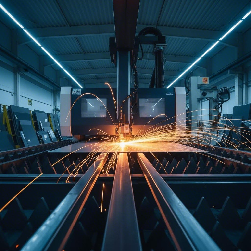
Ever wondered how a flat piece of metal transforms into the precise component you need for your project? Whether you're an engineer designing automotive parts or a DIY enthusiast building custom brackets, sheet metal custom cut services bridge the gap between raw material and finished reality. At its core, this process involves transforming flat metal sheets into specific shapes and designs through advanced cutting, guided by your exact specifications.
Custom metal cutting goes far beyond simply slicing through material. It's a sophisticated process where computer-controlled machines execute precise cuts based on your digital design files. The result? Parts that fit perfectly, perform reliably, and eliminate the frustration of trying to make standard stock work for non-standard applications.
This guide will walk you through the complete journey from design file to finished part. You'll learn about cutting technologies, material selection, gauge fundamentals, file preparation, fabrication workflows, finishing options, cost factors, and how to choose the right fabrication partner.
What Makes Custom Cutting Different from Standard Stock
Imagine walking into a hardware store and picking up a pre-cut metal sheet. Sure, it might be close to what you need, but "close" rarely works in metal fabrication. Standard stock comes in fixed dimensions and generic shapes. You're left trimming, adjusting, and often wasting material to achieve your desired outcome.
Custom cut metals eliminate this compromise entirely. When you work with a professional fabricator, every piece of metal matches your exact requirements. Need a bracket with specific mounting holes at precise locations? A panel with intricate cutouts for ventilation? Complex shapes that would be impossible to achieve by hand? Custom cutting delivers all of this with remarkable accuracy.
The difference also extends to efficiency. With custom cut metal, there's no need for secondary trimming operations or manual adjustments. Parts arrive ready for the next stage of your project, whether that's bending, welding, or final assembly.
The Precision Advantage in Modern Fabrication
Precision isn't just a nice-to-have feature in metal fabrication. It's the foundation that determines whether your project succeeds or fails. Modern sheet metal custom cut services achieve tolerances as tight as +/- 0.005 inches, according to industry fabrication specialists. This level of accuracy means the first part produced will be virtually identical to the thousandth part.
Custom cutting eliminates material waste through specialized nesting software that arranges parts on metal sheets like puzzle pieces, maximizing material utilization while enabling exact specifications that standard stock simply cannot match.
Why does this matter for your project? Consider the downstream effects. When cuts are accurate, parts fit together seamlessly during assembly. There's no forcing, no filing, no frustrated attempts to make pieces work together. This precision translates directly into reduced labor costs, faster production times, and higher-quality finished products.
Professional fabricators use computer numerical control (CNC) technology to guide cutting tools with incredible accuracy. Once your design is programmed, the machine executes cuts consistently every single time. This repeatability is essential for both prototype development and high-volume production runs. Whether you need one piece of metal or ten thousand, each part meets the same exacting standards.
Cutting Technologies and How They Work
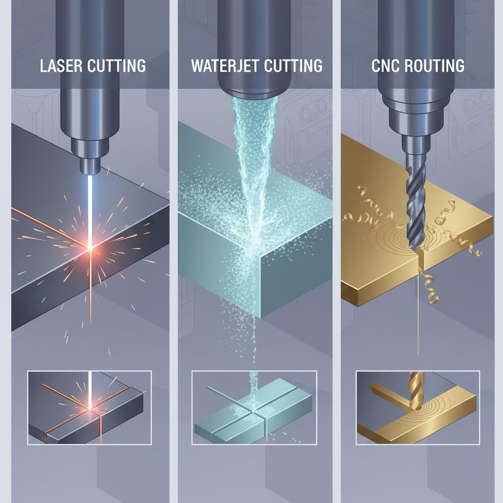
So how exactly does a machine cut through solid metal with such precision? Understanding the science behind each cutting method helps you make smarter decisions about which technology suits your project best. Three primary technologies dominate the custom cutting landscape: laser cutting, waterjet cutting, and CNC routing. Each method cuts metal through fundamentally different mechanisms, creating distinct advantages for specific applications.
Laser Cutting Technology Explained
Imagine focusing sunlight through a magnifying glass, but amplified millions of times. That's essentially how a laser cutter works. A laser cutter generates a highly concentrated beam of light that melts, burns, or vaporizes material along a programmed path. The result? Incredibly precise cuts with minimal material waste.
Modern fabrication facilities typically use fiber lasers ranging from 4kW to 12kW, according to SendCutSend's fabrication guide. These high-powered systems can slice through material at speeds up to 2,500 inches per minute, making laser cutting the fastest method available. Speed translates directly into cost efficiency for most projects.
The laser beam itself is extremely narrow, which brings us to an important concept: kerf. Kerf refers to the width of material removed during cutting, which includes the laser beam width plus any additional material burned away. For laser cutting, kerf is minimal compared to other methods. Professional fabricators automatically compensate for kerf in their software, so your finished parts match your design dimensions exactly.
One consideration with laser cutting is the heat-affected zone (HAZ). Because the process involves thermal energy, the material adjacent to the cut can experience slight property changes. However, the incredibly fast cutting speeds and small beam diameter of modern lasers minimize this effect. For simple geometries, HAZ is virtually nonexistent. Complex designs with many closely spaced cuts require more attention to thermal management.
Laser cutting excels with metals like aluminum, mild steel, stainless steel, copper, and brass. Most metals up to half an inch thick are suitable candidates. However, materials that produce hazardous gases when burned, such as PVC, aren't appropriate for laser processing.
Waterjet Versus Thermal Cutting Methods
What if you need to cut metal without any heat at all? Waterjet cutting offers exactly that solution. This process uses extremely high-pressure water, often mixed with finely crushed garnet abrasive, to erode material along a programmed path. The result is a cold cutting process that completely eliminates heat-affected zones.
Think of it as super-powered erosion. Water pressurized to extreme levels (typically 60,000 to 90,000 PSI) concentrates into a narrow jet that literally wears away material. The abrasive particles act like microscopic cutting tools suspended in the water stream. According to Techni Waterjet, this method achieves tolerances as tight as +/- 0.001 inches, making it the most precise cutting technique available.
The cold cutting advantage matters significantly for certain applications. Aerospace manufacturers, for example, often specify waterjet cutting because regulations prohibit any heat-affected zones on aircraft components. Composite materials like carbon fiber, G10, and phenolic also perform exceptionally well with waterjet processing, as thermal methods can cause delamination or excessively rough edges.
Waterjet cutting produces virtually no dross or burrs, resulting in a superior surface finish along cut edges. The trade-off? Speed. Waterjet is significantly slower than laser cutting, which affects both production timelines and costs. Interior corners must have a minimum radius of 0.032 inches to accommodate the waterjet stream diameter, and holes cannot be smaller than 0.070 inches in diameter.
CNC Router Applications for Sheet Metal
When someone asks "what does CNC mean?" the answer is Computer Numerical Control. The cnc meaning refers to automated machine control through programmed computer instructions. A CNC router applies this technology using a rotating cutting tool that physically removes material, similar to a highly industrial version of a handheld router.
Here's how it works: a cutter spins in a spindle that lowers to plunge into the work material. The machine then moves the cutter along preprogrammed paths based on your design files. Unlike laser or waterjet, this is a contact-based process where the tool physically touches and removes material through mechanical force.
CNC routing offers distinct advantages for composites, plastics, and certain wood materials. The process leaves a superior surface finish while maintaining tolerances of +/- 0.005 inches. Fabricators dial in specific "speeds and feeds" for different materials, adjusting the feed rate (cutting speed) and spindle RPM to optimize surface quality and cutting efficiency.
Because there's physical load on parts during machining, small fixture tabs hold pieces in place during cutting. These tabs prevent movement that could compromise cut quality but may leave small bumps requiring hand finishing. Interior corners on CNC routed parts cannot be sharper than the cutter diameter, typically requiring a minimum radius of 0.063 inches for standard 1/8-inch bits.
One important limitation: parts with extensive material removal (like perforated patterns or grill designs) aren't ideal for CNC routing. Fabricators typically recommend no more than 50% material removal to prevent parts from shifting during processing.
Comparing Cutting Technologies
Choosing the right technology depends on your specific project requirements. This comparison table breaks down the key factors that influence which method best suits your application:
| Factor | Laser Cutting | Waterjet Cutting | CNC Routing |
|---|---|---|---|
| Material Compatibility | Metals (aluminum, steel, stainless, copper, brass); most materials up to 1/2" | All metals, composites, glass, carbon fiber, stone; virtually any material | Composites, plastics, wood, softer metals; materials that don't suit thermal cutting |
| Thickness Range | Thin to 1/2" for most metals | Thin to several inches depending on material | Varies by material; typically thin to medium gauge |
| Typical Kerf Width | ~0.025" | ~0.035" | ~0.125" (1/8" bit) |
| Edge Quality | Excellent; slight striations on thick materials; may require deburring | Excellent; smooth finish with no dross or burrs | Very good; may have tab marks requiring finishing |
| Heat-Affected Zone | Minimal with modern equipment; some concern on complex geometries | None (cold cutting process) | Minimal; friction heat only |
| Typical Tolerances | +/- 0.005" | +/- 0.005" to +/- 0.001" | +/- 0.005" |
| Cutting Speed | Fastest (up to 2,500 ipm) | Slowest | Medium |
| Minimum Interior Corner Radius | Very sharp corners possible | 0.032" | 0.063" (with 1/8" bit) |
Professional fabricators evaluate your material choice, design complexity, tolerance requirements, and production volume to determine which cutting method delivers the best results. In many cases, the decision is straightforward. Aluminum sheet for a prototype enclosure? Laser cutting offers speed and precision. Carbon fiber panel for aerospace? Waterjet eliminates heat concerns. HDPE for food-safe equipment? CNC routing provides the ideal surface finish.
Understanding how each technology cuts metal empowers you to have informed conversations with fabrication partners and optimize your designs for the chosen process. With cutting technology selected, your next consideration becomes equally important: which material best serves your project requirements?
Material Selection for Custom Cut Projects
Now that you understand how cutting technologies work, here's the next critical question: which metal should you actually cut? The material you choose affects everything from cutting method compatibility to edge quality, corrosion resistance, and final project performance. Selecting the wrong material can lead to premature failure, unexpected costs, or fabrication headaches that derail your timeline.
Think of material selection as building a foundation. Get it right, and every subsequent step becomes easier. Get it wrong, and you'll fight problems throughout the entire project. Let's explore the most common materials for custom cutting and what makes each one suitable for specific applications.
Aluminum Alloys and Their Cutting Behavior
Aluminum sheet metal stands out as one of the most versatile options for custom cutting projects. Its combination of lightweight construction, natural corrosion resistance, and excellent formability makes it a go-to choice across industries. But not all aluminum is created equal.
When you order an aluminum sheet for custom cutting, you're typically working with alloys like 5052 or 6061. Each alloy brings different characteristics to your project. The 5052 alloy offers exceptional corrosion resistance and formability, making it ideal for marine applications or parts requiring extensive bending. The 6061 alloy provides higher strength and machines beautifully, which explains its popularity in structural components and precision parts.
- Tensile Strength: Moderate (33,000-45,000 PSI depending on alloy)
- Thermal Conductivity: Excellent (approximately 1500 BTU-in/hr-ft²-°F)
- Corrosion Resistance: Very good; forms protective oxide layer naturally
- Weight: Approximately one-third the weight of steel
- Cutting Behavior: Cuts cleanly with all methods; excellent for laser and waterjet
Aluminum's high thermal conductivity actually works in your favor during laser cutting. Heat dissipates quickly through the material, minimizing heat-affected zones and reducing the risk of warping. According to JLCCNC's material selection guide, aluminum is easier to process than stainless steel, offering better formability, higher thermal conductivity, and lower cutting resistance. This translates to reduced tool wear and faster machining times.
Common applications include aerospace components, electronics enclosures, signage, and architectural panels. When weight matters but you still need reasonable strength, aluminum delivers the best strength-to-weight ratio available.
Steel Grades for Custom Fabrication
Steel remains the workhorse of metal fabrication. Its high strength, relatively low cost, and excellent weldability make it suitable for everything from automotive components to industrial equipment. However, choosing between steel types requires understanding the trade-offs involved.
Cold Rolled Steel
Cold rolled steel offers the smoothest surface finish and tightest dimensional tolerances among steel options. The rolling process at room temperature creates a harder, stronger material than hot-rolled alternatives. This makes cold rolled steel ideal for precision components where surface quality matters.
- Tensile Strength: High (approximately 50,000-85,000 PSI)
- Surface Quality: Excellent; smooth and consistent
- Corrosion Resistance: Poor; requires protective coating or finishing
- Formability: Very good; bends and shapes well
- Cost: Economical for structural applications
The main drawback? Cold rolled steel has virtually no corrosion resistance. Without protective coatings like paint or powder coat, it will rust quickly in humid or outdoor environments. This makes it best suited for indoor applications or projects where you'll apply protective finishes.
Stainless Steel Sheets
When corrosion resistance becomes critical, stainless steel sheet options provide the solution. The chromium content (typically 10.5% or higher) forms a self-healing oxide layer that protects against rust even in aggressive environments.
- Tensile Strength: Very high (75,000-100,000+ PSI depending on grade)
- Thermal Conductivity: Lower than aluminum or carbon steel
- Corrosion Resistance: Excellent; chromium oxide layer self-repairs
- Cutting Behavior: More difficult to process; requires higher power and stricter process control
- Cost: Higher than carbon steel or aluminum
For particularly demanding environments, 316 stainless steel provides superior performance. This marine-grade alloy contains molybdenum, which enhances resistance to chlorides and industrial chemicals. Food processing equipment, medical devices, and coastal installations frequently specify 316 stainless steel for this reason.
Standard 304 stainless works well for most applications where corrosion resistance matters but extreme chemical exposure isn't a concern. Kitchen equipment, architectural trim, and general industrial components typically use 304 grade.
Galvanized Steel: The Best of Both Worlds?
What if you need outdoor durability without stainless steel's higher cost? Galvanized sheet metal offers an economical middle ground. According to Norck's engineering guide, galvanized steel consists of cold rolled steel coated with a protective zinc layer that resists corrosion for extended periods.
- Tensile Strength: Moderate to high (similar to base steel)
- Corrosion Resistance: Good; zinc coating acts as sacrificial barrier
- Durability: Excellent for outdoor applications with moderate exposure
- Cost: Lower than stainless steel; slightly higher than raw cold rolled
- Applications: HVAC ducts, roofing, fencing, outdoor enclosures
The zinc coating works through two mechanisms. First, it creates a physical barrier between the steel and corrosive elements. Second, even when scratched, the zinc sacrificially corrodes before the underlying steel. This "sacrificial anode" property means minor surface damage doesn't immediately lead to rust.
Choose galvanized steel for outdoor structural applications, HVAC components, and general-purpose outdoor use. Choose raw cold rolled steel when you'll apply your own protective finish or when parts remain in controlled indoor environments.
Specialty Metals and Cutting Considerations
Beyond aluminum and steel, specialty metals serve applications where unique properties matter more than cost. Copper and brass both offer characteristics that make them irreplaceable for specific uses.
Copper
Copper's exceptional electrical and thermal conductivity makes it essential for electrical components, heat exchangers, and certain architectural applications. Its natural antimicrobial properties also make it valuable for healthcare and food service environments.
- Tensile Strength: Moderate (approximately 32,000-37,000 PSI for pure copper)
- Electrical Conductivity: Excellent (second only to silver)
- Thermal Conductivity: Outstanding
- Corrosion Resistance: Very good; develops protective patina over time
- Cutting Behavior: Cuts well with laser and waterjet; highly reflective surface requires attention during laser processing
When comparing brass vs bronze, understand that brass is a copper-zinc alloy while bronze is a copper-tin alloy. Brass offers better machinability and a distinctive gold-like appearance, making it popular for decorative hardware and musical instruments. Bronze provides higher strength and superior wear resistance, suiting it for bearings, bushings, and marine hardware.
Brass
Brass combines copper's workability with zinc's strength enhancement. The result is a material that machines beautifully, resists corrosion, and provides aesthetic appeal for visible applications.
- Tensile Strength: Moderate to high (40,000-60,000 PSI depending on alloy)
- Machinability: Excellent; one of the easiest metals to cut and form
- Corrosion Resistance: Very good in most environments
- Appearance: Attractive gold color; takes polish well
- Applications: Decorative hardware, electrical connectors, musical instruments, architectural elements
Both copper and brass cost significantly more than steel or aluminum. However, for applications requiring their specific properties, no substitutes truly work. Electrical bus bars demand copper's conductivity. Decorative nameplates benefit from brass's appearance and workability.
Selecting the right material ultimately comes down to matching properties with requirements. Consider the operating environment, structural demands, aesthetic needs, and budget constraints. A fabrication partner can help evaluate trade-offs, but understanding these fundamentals puts you in control of the conversation. With your material selected, the next essential consideration becomes thickness. How do gauge numbers translate to actual dimensions, and what thickness works best for your application?
Metal Gauge and Thickness Fundamentals
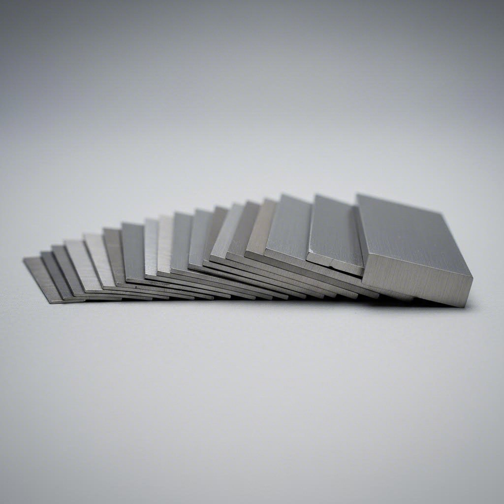
Here's something that trips up even experienced fabricators: the gauge system runs backward. A higher gauge number means thinner material. Sounds counterintuitive, right? Understanding metal gauge thickness is essential for successful sheet metal custom cut projects because thickness directly affects cutting method selection, edge quality, and what you can actually accomplish with the finished part.
The gauge system dates back to the 1800s, before standardized thickness measurements existed. According to SendCutSend's technical guide, manufacturers originally measured sheet metal by weight rather than thickness because manufacturing processes produced inconsistent results. Measuring by weight gave a more accurate representation of average thickness than any single point measurement.
Reading the Gauge System Correctly
Think of gauge numbers like a countdown. The number represents how many times wire was drawn through progressively smaller dies during manufacturing. More drawing operations created thinner material, hence higher gauge numbers equal thinner sheets. An 18-gauge steel sheet is thicker than a 20-gauge one, even though 20 is a larger number.
Here's where it gets tricky: different metals use different gauge charts. The 10 gauge steel thickness differs from 10 gauge aluminum or stainless steel. According to FabWorks, using the wrong gauge chart can result in thickness differences of 0.033 inches or more, well outside acceptable tolerances for most designs.
This reference table shows common gauge sizes with their decimal equivalents and typical applications for steel:
| Gauge | Thickness (inches) | Thickness (mm) | Typical Applications |
|---|---|---|---|
| 10 Gauge | 0.1345" | 3.42 mm | Heavy structural components, industrial equipment, trailer beds |
| 11 Gauge | 0.1196" | 3.04 mm | Automotive frames, heavy-duty brackets, machinery guards |
| 12 Gauge | 0.1046" | 2.66 mm | Structural panels, equipment housings, mounting plates |
| 14 Gauge | 0.0747" | 1.90 mm | Automotive body panels, enclosures, medium-duty brackets |
| 16 Gauge | 0.0598" | 1.52 mm | HVAC ductwork, electronics enclosures, decorative panels |
Notice the significant jump between gauges. The 11 gauge steel thickness at 0.1196 inches is notably thinner than 10 gauge at 0.1345 inches. Similarly, 16 gauge steel thickness at 0.0598 inches represents material nearly half as thick as 12 gauge. These differences matter tremendously when specifying parts for structural or precision applications.
Thickness Limits by Cutting Method
Your material thickness directly determines which cutting technologies can handle your project effectively. Each method has sweet spots and limitations that affect both feasibility and quality.
Laser Cutting Thickness Limits
Modern fiber lasers handle most metals up to half an inch thick. However, optimal performance typically occurs in thinner materials. A 14 gauge steel thickness of 0.0747 inches cuts quickly with excellent edge quality. Push into thicker territory, and cutting speeds slow while heat input increases. For materials approaching the half-inch limit, you may notice slight striations on cut edges.
Waterjet Cutting Thickness Limits
Waterjet excels with thicker materials where laser cutting struggles. This cold cutting process handles material several inches thick without heat-affected zones. However, thicker materials require slower cutting speeds, increasing processing time and cost. Thin materials (below 16 gauge) may experience slight edge taper if not carefully controlled.
CNC Routing Thickness Limits
CNC routing works best with thinner to medium gauge materials. Very thick stock requires multiple passes, increasing processing time. Very thin material may flex or vibrate during cutting, potentially affecting edge quality. The sweet spot typically falls between 14 and 10 gauge for most applications.
Matching Gauge to Application Requirements
Selecting the right steel gauge thickness involves balancing multiple factors. Thicker isn't always better, and thinner isn't always cheaper when you consider the complete picture.
- Structural requirements: Load-bearing applications demand thicker gauges. A bracket supporting heavy equipment needs 10 or 11 gauge material, while a decorative cover might work fine at 16 gauge.
- Forming considerations: Thinner materials bend more easily with tighter radii. If your design includes sharp bends, you may need thinner gauge material to avoid cracking.
- Weight constraints: Aerospace and automotive applications often prioritize weight reduction. Specifying the minimum acceptable thickness saves weight without sacrificing function.
- Cost implications: Thicker material costs more per square foot and takes longer to cut. However, specifying too thin may require additional reinforcement, negating savings.
- Edge quality: Cutting thick materials produces rougher edges that may require secondary finishing. Thinner gauges typically yield cleaner cuts with less post-processing.
Processing time scales with thickness. Cutting through 10 gauge steel takes significantly longer than 16 gauge material, directly affecting project costs and timelines. When tolerances allow, choosing a slightly thinner gauge can reduce both cutting time and material expense.
Before finalizing your gauge selection, consult with your fabrication partner about material availability. As industry experts recommend, designing for thicknesses your manufacturer stocks prevents costly delays and adjustments. With gauge and thickness understood, your next step involves preparing design files that communicate your exact specifications to cutting equipment.
Preparing Design Files for Custom Cutting
You've selected your material and determined the right gauge. Now comes the step that determines whether your sheet metal custom cut project moves smoothly into production or stalls with revision requests: file preparation. Think of your design file as the instruction manual for cutting machines. A clean, properly formatted file translates directly into faster quotes, fewer errors, and parts that match your exact specifications.
The difference between a well-prepared file and a problematic one? According to DXF4You's fabrication guide, properly optimized files minimize errors, save material, and reduce cutting time. Poorly prepared files cause machine malfunctions, wasted material, and substandard results. Taking time upfront to prepare files correctly saves significant headaches downstream.
File Formats That Cutting Services Accept
Not all file formats communicate equally well with CNC cutting equipment. Fabrication shops work with vector-based files that define geometry through mathematical equations rather than pixels. This allows machines to follow precise cutting paths at any scale without quality loss.
The most universally accepted format is DXF (Drawing Exchange Format). Originally developed by Autodesk, DXF files have become the industry standard because virtually every CAD program can export them and every cutting system can read them. When you submit a DXF file, the fabricator imports your geometry directly into their nesting and cutting software.
DWG files (AutoCAD's native format) also work well, though some shops may convert them to DXF before processing. Both formats preserve the vector geometry essential for accurate cutting paths.
Vector files from programs like Adobe Illustrator (AI, EPS, PDF) can work for simpler projects, though they may require conversion. These formats handle custom cut metal shapes effectively when properly prepared, but they sometimes include elements that don't translate cleanly to cutting instructions.
- DXF: Most widely accepted; compatible with all major CAD programs and cutting systems
- DWG: AutoCAD native format; excellent compatibility with fabrication software
- Vector PDF: Acceptable for simple shapes; may require conversion
- AI/EPS: Works for basic designs; verify with fabricator before submitting
- STEP/IGES: 3D formats used when parts include forming operations
Avoid submitting raster images (JPG, PNG, BMP) as primary design files. These pixel-based formats cannot define the precise vector paths cutting machines require. If you only have a raster image, you'll need to trace or redraw it as vector geometry before submission.
Design Rules for Clean Cuts
Even the correct file format won't help if your geometry contains errors that confuse cutting equipment. Following established design rules ensures your custom cut metal shapes translate accurately from screen to finished part.
- Closed contours: Every shape must form a completely closed path. Open paths leave the cutting machine uncertain about what's inside versus outside the part. A gap of even 0.001 inches can cause processing failures.
- Minimum feature sizes: Small details must account for kerf width and material thickness. Holes smaller than material thickness may not cut cleanly. Interior slots need sufficient width for the cutting beam or jet to pass through.
- Corner radii requirements: Sharp interior corners are impossible with waterjet (minimum 0.032" radius) and CNC routing (minimum equals cutter diameter). Laser cutting handles sharper corners but may leave slight radius at high speeds.
- Text handling: Convert all text to outlines or paths before export. Live text may display incorrectly if the fabricator's system lacks your fonts. Text milling and cutting work properly only when letters become vector geometry.
- Line weights: Set all cutting paths to a single, consistent line weight. Varying thicknesses can confuse some processing software about which lines represent actual cuts.
- Layer organization: Separate cutting lines from dimensions, notes, and centerlines. Many fabricators expect cutting geometry on a specific layer (often named "Cut" or "0").
Minimum feature dimensions vary by cutting method and material. As a general rule, maintain features at least 1.5 times material thickness for reliable results. Consult your fabricator's design guidelines for specific limitations based on their equipment and your chosen material.
Avoiding Common File Preparation Errors
Certain mistakes appear repeatedly in design file submissions. Knowing what to check before sending files can dramatically reduce revision cycles and get your parts into production faster.
Overlapping or Duplicate Lines
When geometry is copied, imported from other files, or created through boolean operations, duplicate lines often stack directly on top of each other. These invisible duplicates cause the cutting machine to trace the same path multiple times, wasting time and potentially affecting edge quality. According to DXF preparation experts, always run a duplicate detection or cleanup function before export.
Open Paths and Incomplete Geometry
Gaps in your outlines, even microscopic ones, prevent proper processing. Use your CAD program's path verification tools to identify and close any open contours. Most professional software includes a "check geometry" or "verify paths" function specifically for this purpose.
Scaling Errors
A 10-inch part accidentally saved in millimeters becomes a 10-millimeter part, roughly the size of a fingernail. Always verify units before export and include overall dimensions in your file for fabricator reference. Many shops will catch obvious scaling issues, but subtle errors might slip through.
Excessive Nodes
Curves created from traced images or converted from other formats often contain far more nodes than necessary. These extra points slow processing and can create slight irregularities in cut edges. Reduce nodes to the minimum required to maintain shape accuracy, typically using your CAD program's simplify or optimize function.
Construction Lines Left in Files
According to SolidWorks fabrication specialists, forgetting to remove construction lines or sketches from your DXF file is a common mistake that leads to confusion during manufacturing. These reference lines may be misinterpreted as cutting geometry. Before exporting, delete or hide all non-essential lines, centermarks, and construction geometry.
Bend Considerations Missing
If your flat pattern will become a formed part, bend allowances and relief cuts must be incorporated during the design phase. Failing to account for material stretch during bending results in parts with incorrect final dimensions. Work with your fabricator to confirm k-factor and bend deduction values for your specific material.
Proper file preparation directly impacts your project timeline. Clean files receive faster end quotations because fabricators spend less time fixing geometry issues. Manufacturing delays decrease when parts process correctly the first time. Taking an extra hour to verify your file can save days in the production schedule.
Before submitting files, run through this quick verification checklist: all paths closed, no duplicates, correct units and scale, text converted to outlines, construction lines removed, and geometry organized on appropriate layers. With your design files properly prepared, you're ready to understand the complete fabrication workflow that transforms flat cuts into finished components.
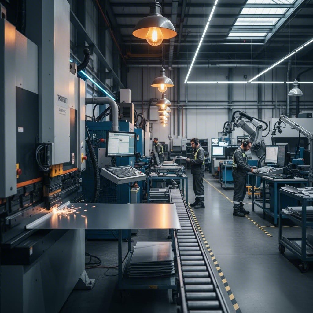
The Complete Fabrication Workflow
Your design files are submitted, your material is selected, and cutting begins. But here's what many people don't realize: the cutting operation is just the starting point. A flat piece of metal rarely becomes a finished product straight off the cutting table. The real transformation happens through secondary operations that bend, join, thread, and finish your parts into functional components.
Understanding this complete workflow matters because decisions made at the cutting stage ripple through every subsequent operation. A poorly positioned cut affects bend accuracy. Incorrect hole placement creates hardware insertion problems. Edge quality from cutting determines welding success. When you see the full picture, you can design smarter from the start.
From Flat Cut to Formed Part
Imagine holding a freshly cut stainless sheet in your hands. It's flat, precise, and exactly matches your design dimensions. Now picture that same piece transformed into a three-dimensional enclosure with perfect 90-degree bends, threaded mounting holes, and a professional powder-coated finish. That transformation follows a carefully orchestrated sequence.
According to FabWorks' design guide, the order in which operations are performed greatly affects the manufacturability and accuracy of the final part. Improper sequencing can lead to distortion, misalignment, or even part failure. This is why professional fabricators follow established workflows rather than improvising.
- File Submission and Review: Your design files enter the fabricator's system for manufacturability analysis. Engineers verify geometry, check for potential issues, and confirm material specifications.
- Nesting and Material Preparation: Parts are arranged on raw sheets to maximize material utilization. The selected sheet metal is loaded onto cutting equipment.
- Primary Cutting Operation: Laser, waterjet, or CNC routing executes the programmed cut paths, creating your flat parts from raw stock.
- Deburring and Edge Finishing: Cut edges are cleaned to remove any burrs, dross, or sharp edges that could affect subsequent operations or pose handling hazards.
- Bending and Forming: Press brakes and forming equipment transform flat patterns into three-dimensional shapes according to your design specifications.
- Hardware Insertion: PEM nuts, studs, standoffs, and other fastening hardware are pressed or inserted into designated locations.
- Tapping and Countersinking: Threaded holes are cut, and countersinks are added for flush fastener installation.
- Welding and Joining: Components are joined through spot welding, MIG welding, TIG welding, or aluminum welding processes as required.
- Surface Finishing: Parts receive powder coating, anodizing, plating, or other protective and decorative finishes.
- Quality Inspection: Dimensional verification and visual inspection confirm parts meet specifications before packaging and shipping.
Each step builds upon the previous one. Skip a step or perform operations out of sequence, and you'll encounter problems. Trying to insert hardware after powder coating? The coating prevents proper seating. Bending before deburring? Sharp edges can damage forming dies and create safety hazards.
Secondary Operations That Add Value
Secondary operations transform simple flat cuts into functional components. Understanding each operation helps you design parts that process efficiently and perform reliably.
Bending and Press Brake Forming
Bending creates the three-dimensional geometry that gives sheet metal parts their structural rigidity and functional form. A press brake uses matched punch and die sets to force material into precise angles. According to sheet metal fabrication experts, bend allowance and bend deduction are critical concepts that help determine the precise dimensions of the part after bending.
Here's the critical connection to cutting: bend allowances must be calculated into your flat pattern during the design phase. Material stretches along the outside of a bend and compresses on the inside. If your flat pattern doesn't account for this dimensional change, your finished part won't match intended dimensions. The K-factor, which defines the ratio of the material's neutral axis to sheet thickness, determines exactly how much material length to add or subtract.
Minimum bend radii also connect directly to material selection discussed earlier. As noted in design guidelines, the minimum bend radius is the smallest possible radius you can apply without causing cracking or material failure. Designing bends with smaller radii than the material can handle may result in cracks, weak points, or failure during manufacturing.
Hardware Insertion
Many sheet metal parts require threaded fastening points, but tapping thin material often provides insufficient thread engagement. PEM hardware solves this problem. These specially designed fasteners press into prepared holes, creating permanent threaded mounting points, standoffs, or captive nuts directly in the sheet metal.
The cutting phase must create precisely sized holes for each hardware type. Too small, and the hardware won't seat properly. Too large, and retention strength suffers. Professional fabricators specify exact hole diameters based on hardware specifications and material thickness.
Tapping and Countersinking
When material thickness permits, direct tapping creates internal threads without additional hardware. Thicker gauge materials, typically 10 gauge and heavier, provide enough material for reliable thread engagement. Countersinking creates conical recesses that allow flat-head fasteners to sit flush with the surface.
Both operations require accurate hole positioning during cutting. A mislocated pilot hole means a mislocated thread or countersink. This is why precise cutting directly impacts every downstream operation.
Welding and Joining
Steel fabrication frequently involves welding multiple components together. Different materials and applications call for different welding methods. Spot welding creates discrete connection points by passing electrical current through stacked sheets, fusing them at contact points. MIG and TIG welding deposit filler material to create continuous seams.
Aluminum welding presents unique challenges due to the material's thermal properties and oxide layer. Specialized equipment and techniques ensure strong, clean welds without porosity or cracking. Working with a stainless sheet requires yet different parameters to maintain corrosion resistance in the heat-affected zone.
Cut edge quality directly affects weld quality. Rough, oxidized, or contaminated edges produce weaker welds with potential defects. Clean cuts from proper cutting parameters create edges ready for reliable joining.
Planning for Post-Cut Processing
Smart design anticipates every operation your part will undergo. Thinking through the complete sheet metal fabrication workflow during initial design prevents costly revisions and manufacturing delays.
Bend Relief and Clearance
According to fabrication design guides, bend relief is an additional feature added to the design to prevent tearing or deformation near the bend area. When bends occur near edges or other features, material wants to stretch and tear. Small relief cuts at bend intersections allow material to deform without damage.
Your cutting file must include these relief cuts. They're not optional additions the fabricator can skip. Design them in from the start based on material thickness and bend radius specifications.
Hardware Location Planning
Consider where hardware insertion happens in the workflow. PEM hardware typically installs before bending because press brake dies might interfere with installed standoffs or studs. Threaded inserts may install before or after forming depending on accessibility. Plan hardware locations that remain accessible throughout the manufacturing sequence.
Distortion Zone Awareness
Material adjacent to bends experiences stress that can affect nearby features. Holes placed too close to bend lines may distort into ovals during forming. Edges near bends may wave or buckle. Maintain adequate clearance between bend lines and critical features, typically 4-6 times material thickness for most applications.
Finishing Sequence Considerations
Some finishing operations must occur before final assembly, while others work better afterward. Powder coating before welding creates problems because coating burns off in welded zones. Anodizing after forming ensures complete coverage including interior surfaces. Thread masking prevents finish from filling threaded holes. Plan your sequence to achieve complete, uniform finishing without damaging functional features.
The complete fabrication workflow transforms simple flat cuts into sophisticated finished components. Each operation depends on proper execution of previous steps. Cutting quality affects forming accuracy. Forming accuracy affects hardware fit. Hardware placement affects assembly success. Understanding these connections empowers you to design parts that move smoothly through production and perform reliably in service. With the fabrication workflow understood, the next consideration becomes the finishing options that protect and enhance your custom cut parts.
Finishing Options for Custom Cut Parts
Your parts are cut, formed, and assembled. But without proper finishing, even precision-crafted components remain vulnerable to corrosion, wear, and environmental damage. The finishing step transforms raw fabricated metal into durable, attractive products ready for real-world service. Whether you need vibrant colors for consumer products or maximum corrosion protection for outdoor equipment, understanding your finishing options helps you make choices that enhance both performance and appearance.
Finishing isn't just cosmetic. According to industry finishing specialists, surface finishing significantly affects part durability, corrosion resistance, and appearance. The right finish can extend component life by years while the wrong choice leads to premature failure. Let's explore the most common finishing methods for sheet metal custom cut projects.
Powder Coating for Durability and Color
Imagine painting without liquid paint. That's essentially what powder coating achieves. This dry application process uses electrostatically charged powder particles that cling to grounded metal parts before curing in an oven. The result? A tough, uniform finish that resists chipping, scratching, and fading far better than conventional paint.
Here's how the process works: technicians first clean your parts thoroughly to remove oils, oxides, and contaminants. Next, a spray gun applies negatively charged powder particles that are attracted to the grounded metal surface. The powder adheres uniformly even to complex geometries. Finally, parts enter a curing oven where heat transforms the powder into a continuous, cross-linked coating typically 60-120 micrometers thick.
Powder coat finishes excel in demanding environments. According to Gabrian's finishing comparison, powder coatings are commonly seen in outdoor equipment and parts that require brilliant colors and resistance to fading along with excellent durability. Automotive components, outdoor furniture, industrial equipment, and architectural elements frequently specify powder coating for these reasons.
The color and texture options are virtually unlimited. Glossy, matte, textured, metallic, and even multi-tone effects are all achievable. Unlike anodizing, powder coating works on steel, aluminum, and other metals without restriction. This versatility makes it the go-to choice when you need consistent color matching across different materials in an assembly.
One consideration: powder coating adds thickness. That 60-120 micrometer layer affects dimensional tolerances on precision-fit parts. Threaded holes require masking to prevent coating from filling threads. Mating surfaces may need masking or post-coating machining to maintain proper fit.
Anodizing Aluminum Parts
What if you could enhance aluminum's natural protection without adding any coating thickness to speak of? Anodizing does exactly that. This electrochemical process thickens aluminum's natural oxide layer, creating an integral protective surface that's actually part of the metal rather than a coating on top of it.
The process submerges aluminum parts in an electrolytic bath and runs electrical current through them. Using the aluminum as the anode in the circuit accelerates oxidation on the metal's surface. According to finishing experts, this artificial oxide layer enhances wear resistance, corrosion protection, heat dissipation, and even improves adhesion for subsequent glue or primer applications.
Anodized aluminum offers distinct advantages for precision applications. The process adds minimal dimensional change, making it ideal for parts with tight tolerances. The resulting surface is extremely hard and wear-resistant. Electronics enclosures, aerospace components, sporting goods, and architectural elements commonly specify anodizing for these benefits.
Color options differ from powder coating. Anodizing accepts dyes that penetrate the porous oxide layer before sealing, creating permanent coloration that won't chip or peel. However, the color range is more limited than powder coating, and colors tend toward translucent rather than opaque. Classic anodized finishes include clear, black, bronze, and various metallic tones.
Three main types exist: Type I (chromic acid) produces thin layers for aerospace applications, Type II (sulfuric acid) is the most common and cost-effective option, and Type III (hard anodizing) creates extremely thick, wear-resistant surfaces for demanding mechanical applications.
Important limitation: anodizing works only on aluminum. Steel, copper, and brass require different finishing approaches. Additionally, high-silicon aluminum alloys may show uneven coloration or require special processing.
Surface Preparation and Finishing Sequences
Before any finish can adhere properly, surfaces must be prepared correctly. Bead blasting and tumbling serve as both standalone finishes and preparation steps for subsequent coating operations.
Bead Blasting
Bead blasting propels fine media against part surfaces to create uniform matte textures. Glass beads produce smooth, satin finishes while aluminum oxide creates more aggressive textures. This process removes surface imperfections, oxidation, and scale while providing excellent adhesion for subsequent coatings.
For corrugated metal panels and architectural applications, bead blasting creates attractive uniform surfaces that hide minor fabrication marks. The process also works as a standalone finish for parts where a non-reflective appearance matters more than maximum corrosion protection.
Tumbling
Tumbling places parts in rotating barrels with abrasive media that gradually smooths edges and surfaces through controlled friction. This deburring method works particularly well for high-volume small parts where individual hand finishing would be prohibitively expensive.
Tumbling removes sharp edges that could cause handling injuries or interfere with assembly. It also creates consistent surface texture across large batches of parts. For components destined for powder coating or plating, tumbled surfaces accept finishes more uniformly than rough-cut edges.
Sequencing Decisions
When should finishing happen in your fabrication workflow? The answer depends on your specific operations and requirements.
- Finish after all forming operations: Bending and forming can crack or damage existing finishes. Complete all mechanical operations before applying powder coat or anodizing.
- Finish before hardware insertion: Some hardware types install better on finished surfaces. Confirm with your fabricator based on specific hardware specifications.
- Never finish before welding: Coatings burn off in welded zones, creating contamination and weld quality issues. Always weld first, then finish.
- Mask critical features: Threaded holes, mating surfaces, and grounding points often require masking to remain uncoated.
- Consider multi-step approaches: Some projects benefit from pre-treatment (blasting), primary forming, secondary operations, then final coating.
Comparing Finishing Methods
Selecting the right finish requires balancing durability, appearance, cost, and material compatibility. This comparison helps you evaluate options based on your specific project requirements:
| Finishing Method | Durability | Cost Range | Color Options | Suitable Materials |
|---|---|---|---|---|
| Powder Coating | Excellent; resists chips, scratches, UV fading | $0.12-$0.35/cm² | Virtually unlimited colors and textures | Steel, aluminum, most metals |
| Type II Anodizing | Very good; integral oxide layer resists wear | $0.10-$0.30/cm² | Limited; clear, black, bronze, select colors | Aluminum only |
| Type III Hard Anodizing | Outstanding; extremely hard and wear-resistant | Higher than Type II | Limited; typically dark gray to black | Aluminum only |
| Bead Blasting | Low; no corrosion protection alone | $0.05-$0.15/cm² | Natural metal color with matte texture | All metals |
| Tumbling | Low; edge refinement only | Low; batch processing efficient | Natural metal color | All metals |
| Electroplating | Good to excellent depending on plating type | $0.25-$0.60/cm² | Metallic finishes (chrome, nickel, zinc) | Most metals with proper prep |
Your choice ultimately depends on application requirements. Outdoor structural components exposed to weather benefit from powder coating's combination of protection and color options. Precision aluminum housings for electronics often specify anodizing for its dimensional stability and heat dissipation properties. Industrial machinery components might use hard anodizing for maximum wear resistance.
According to sheet metal finishing guides, selecting the appropriate finish depends on several factors including the material, intended use, and environmental conditions the part will face. Consider whether your parts will see outdoor exposure, mechanical wear, chemical contact, or primarily cosmetic requirements.
Cost factors extend beyond per-part finishing prices. Setup costs for small batches can be significant with powder coating. Masking requirements add labor time. Multi-step finishing processes increase both cost and lead time. Work with your fabricator early to understand total finishing costs based on your specific requirements and quantities.
With finishing options understood, you're nearly ready to finalize your project. The remaining considerations involve understanding what drives custom cutting costs and how to select the right fabrication partner to bring your designs to life.
Understanding Custom Cutting Costs
Ever wondered why two seemingly similar parts receive dramatically different quotes? Pricing for custom cut sheet metal involves far more than just material weight. Understanding what drives costs empowers you to optimize designs, ask informed questions, and ultimately get better value from your fabrication projects. Let's break down the factors that influence your quote and explore practical strategies for reducing costs without compromising quality.
What Drives Custom Cutting Costs
When a fabricator calculates your quote, they're evaluating multiple variables that each contribute to the final price. According to SendCutSend's pricing analysis, factors range from material selection to design complexity, and understanding their relative impact helps you make smarter decisions.
Here are the primary cost drivers, listed roughly in order of typical impact:
- Material type and grade: The base metal significantly affects pricing. A custom steel sheet costs less than stainless steel, while specialty alloys command premium prices. Interestingly, large fabricators who purchase thousands of tons of material can offer competitive pricing even on materials that seem expensive at retail.
- Material quantity used: Larger parts consume more raw stock. When you cut metal sheet to size, the square footage directly influences material costs. Minimizing part dimensions where specifications allow reduces this expense.
- Cutting complexity and time: Intricate designs with many curves, small features, and tight tolerances take longer to cut. According to fabrication experts, a complex part with detailed geometry can cost significantly more than a simpler design from identical material.
- Thickness: Thicker materials require slower cutting speeds and more machine power. A metal cut to size from 10-gauge stock processes slower than the same shape from 16-gauge material.
- Secondary operations: Bending, hardware insertion, tapping, and welding each add processing steps. Every additional operation increases labor, machine time, and quality control requirements.
- Finishing requirements: Powder coating, anodizing, or plating adds both material costs and processing time. A raw aluminum part at $27 might cost $43 with a powder coat finish, according to industry examples.
- Quantity ordered: Setup costs spread across more units significantly reduce per-part pricing. The first part is always the most expensive due to programming, setup, and handling overhead.
Material price volatility also affects quotes. Steel, aluminum, and copper prices fluctuate based on global supply chain conditions and market demand. Locking in material early or maintaining flexibility in specifications can help manage this uncertainty.
Optimizing Designs for Better Pricing
Smart design decisions made early dramatically reduce manufacturing costs. According to MakerVerse's cost reduction guide, simpler designs translate to smoother fabrication processes and lower prices.
Nesting efficiency offers one of the biggest opportunities for savings. When fabricators arrange your parts on metal sheets, they use specialized software to fit pieces together like puzzle pieces. Designs that nest efficiently waste less material. Consider how your part shapes might fit together on a standard sheet size. Rectangular parts with minimal curves often nest better than complex organic shapes.
Material utilization extends beyond nesting. Using standard sheet sizes, thicknesses, and grades avoids premium pricing for custom specifications. Every unique requirement can increase costs and lead times. Stick to commonly stocked materials whenever your application allows.
Design simplification pays dividends throughout the workflow. Evaluate each feature in your design and ask whether it's truly essential. Unnecessary complexity adds cutting time, increases potential for issues, and drives up costs. Features like very small holes, intricate internal cutouts, or extremely tight tolerances require more careful processing.
Consider these optimization strategies:
- Use standard tool sizes for holes and corners to avoid custom tooling setup
- Maintain minimum feature sizes appropriate to your cutting method
- Reduce the number of bends when possible, as each bend adds processing time
- Choose readily available materials rather than specialty alloys unless performance demands them
- Design bend radii that match standard tooling to eliminate die changes
According to fabrication cost experts, maximizing material use through efficient nesting during the design phase ensures cost-effective quotations and production. Taking time to optimize before requesting quotes often yields better pricing than negotiating afterward.
Volume Considerations and Quantity Breaks
Perhaps no factor affects per-part pricing more dramatically than order quantity. The economics of fabrication favor larger batches because setup costs, programming time, and handling overhead spread across more units.
Consider this example from industry pricing data: a small zinc-plated steel part costs approximately $29 when ordering just one unit. Order ten of the same part, and the price drops to around $3 per piece. That's nearly a 90% reduction in per-unit cost simply by increasing quantity. Setup, programming, and first-article inspection happen once regardless of whether you order one part or one hundred.
Most materials see discounts starting with the second part and continuing through increasingly larger orders. Some fabricators offer quantity breaks at standard thresholds: 10, 25, 50, 100, and 500 pieces. Others use sliding scales where pricing adjusts continuously based on volume.
Planning ahead creates opportunities for savings. If you know you'll eventually need a custom metal plate in larger quantities, consider ordering the full anticipated volume upfront rather than placing multiple small orders. The savings often outweigh inventory carrying costs.
Consolidation offers another approach. Ordering multiple different parts simultaneously or combining several designs into a single order can streamline processing and reduce overall costs. Fabricators may offer better pricing when they can process related parts together, minimizing material changeovers and shipping complexity.
Lead time flexibility also affects pricing. Rush orders often incur premiums due to overtime labor or schedule disruption. When your timeline allows, standard lead times typically yield better pricing than expedited processing.
Understanding these cost dynamics helps you approach quotes strategically. Rather than simply accepting the first price, consider how design modifications, quantity adjustments, or timing changes might reduce costs while still meeting your project requirements. With cost factors understood, your final consideration becomes selecting the right fabrication partner to execute your project successfully.
Choosing the Right Custom Cutting Partner
You've mastered the technical details. You understand cutting technologies, material properties, gauge specifications, file preparation, and cost dynamics. Now comes perhaps the most consequential decision in your sheet metal custom cut journey: selecting the fabrication partner who will transform your designs into reality. The wrong choice leads to missed deadlines, quality issues, and frustrating communication gaps. The right partner becomes an extension of your team, adding value far beyond simple metal processing.
When searching for "sheet metal fabrication near me" or browsing metal fabricators in your region, the options can feel overwhelming. Every shop claims quality work and competitive pricing. How do you distinguish genuine capability from marketing promises? By evaluating partners against specific criteria that predict project success.
Evaluating Fabrication Partner Capabilities
Not all fabrication shops offer equivalent capabilities. Some specialize in quick-turn prototypes while others excel at high-volume production runs. Some outsource secondary operations while others handle everything under one roof. Understanding these differences helps you find the right fit for your specific project requirements.
According to TMCO's fabrication selection guide, full-service integrated facilities streamline the entire process under one roof, providing tighter control over production, faster turnaround times, and consistent quality standards. When your sheet metal near me search yields multiple options, prioritize those with comprehensive in-house capabilities.
Key capabilities to verify include:
- Cutting technology range: Does the shop offer laser cutting, waterjet, and CNC routing? Multiple technologies mean flexibility to match the optimal process to your project.
- Forming and bending equipment: Modern press brakes with precise angle control ensure accurate bends. Ask about maximum bend length and tonnage capacity.
- Secondary operation capabilities: Hardware insertion, tapping, countersinking, and welding handled in-house eliminate coordination between multiple vendors.
- Finishing options: Powder coating, anodizing, plating, and surface preparation under one roof simplify project management.
- Assembly and testing: For complex projects, partners who can assemble and test completed units add significant value.
Experience matters significantly. According to metal fabrication experts, experienced custom metal fabricators understand variations in metals and how each performs during cutting, forming, and welding. They anticipate challenges before they become costly problems.
When evaluating potential partners, ask directly about their experience with your specific materials and applications. A shop that primarily works with mild steel may struggle with the nuances of aluminum welding or stainless sheet processing. Industry-specific experience often translates to better outcomes and fewer surprises.
Quality Certifications That Matter
Certifications provide objective evidence of a fabricator's commitment to documented quality systems. While certifications alone don't guarantee excellent results, their absence should raise questions about process consistency and quality controls.
According to Hartford Technologies' certification guide, quality certifications demonstrate commitment to the customer and to their profession, producing premium components while providing added assurance for buyers that manufactured items meet requirements.
The most relevant certifications for sheet metal custom cut projects include:
- ISO 9001: The most universal manufacturing certification, ISO 9001 establishes requirements for a robust quality management system. This certification confirms that products and services comply with customer expectations and regulatory mandates.
- IATF 16949: Specifically developed for automotive manufacturing, this global quality management standard builds upon ISO 9001 with additional requirements for product design, production processes, and continuous improvement. Automotive applications demand this certification.
- AS9100: Essential for aerospace applications, this certification confirms parts meet the safety, quality, and technical standards required by aviation regulations.
- ISO 13485: Required for medical device manufacturing, ensuring all components are designed and manufactured with patient safety as the priority.
Beyond certifications, evaluate the fabricator's quality control practices directly. According to industry best practices, a strong quality framework may include first-article inspection, in-process dimensional checks, weld integrity testing, final inspection, and use of Coordinate Measuring Machines (CMMs). Ask potential partners to walk you through their inspection process and quality documentation.
For automotive applications specifically, IATF 16949 certification serves as a critical differentiator. Manufacturers like Shaoyi (Ningbo) Metal Technology maintain this certification while offering comprehensive capabilities from 5-day rapid prototyping to automated mass production. Their combination of IATF 16949-certified quality, comprehensive DFM support, and 12-hour quote turnaround exemplifies the quality markers to seek in a fabrication partner for demanding applications.
From Prototype to Production Scaling
Your ideal partner supports both your immediate prototype needs and future production scaling. According to manufacturing experts, your ideal partner is one who can support both current needs and future growth without sacrificing quality during the transition.
Rapid prototyping capabilities matter tremendously in today's fast-moving development cycles. The ability to receive functional parts within days rather than weeks accelerates your design iteration and reduces time to market. Look for partners offering:
- Fast quote turnaround: Quality partners provide quotes within hours, not days. Rapid quoting demonstrates both technical capability and customer focus.
- Prototype lead times: The best partners deliver prototype parts in 5-7 days or less for standard materials and processes.
- Design for Manufacturability support: Partners who review your designs and suggest improvements before cutting add value beyond simple processing.
- Low minimum quantities: True prototyping partners accept orders as small as one piece without excessive setup premiums.
Production scalability ensures your partner grows with your project. According to industry guidance, a fabrication company must be able to scale production from prototypes to full production runs without sacrificing quality. Ask potential partners about their capacity, automation level, and experience transitioning projects from prototype to volume production.
Communication quality often determines project success. According to fabrication experts, transparent communication is equally critical to technical capability. A reliable fabricator provides clear timelines, project updates, and realistic expectations, preventing costly surprises.
When comparing fabrication shops near me, evaluate responsiveness during the quoting process as an indicator of future communication. Partners who answer questions promptly, provide detailed explanations, and proactively identify potential issues demonstrate the communication commitment your project requires.
Finally, consider the complete value proposition rather than price alone. According to metal fabrication selection guidance, hiring a fabricator isn't just a purchasing decision but a long-term investment in the performance and reliability of your products. The right partner contributes engineering support, advanced technology, strong quality systems, and a collaborative approach that adds value beyond the metal itself.
Your sheet metal custom cut project deserves a fabrication partner who combines technical excellence with genuine partnership. Take time to evaluate capabilities, verify certifications, and assess communication quality. The investment in finding the right partner pays dividends throughout your project and builds a relationship that supports future success.
Frequently Asked Questions About Sheet Metal Custom Cut Services
1. How much does custom sheet metal cost?
Custom sheet metal costs vary based on material type, thickness, cutting complexity, and quantity. Basic steel parts start around $3-5 per piece in volume, while single prototypes can cost $25-40 or more. Stainless steel and specialty metals command higher prices. Finishing adds $0.10-0.35 per square centimeter. IATF 16949-certified manufacturers like Shaoyi offer competitive pricing with 12-hour quote turnaround to help you understand exact costs for your specific project requirements.
2. How much does metal cutting cost?
Metal cutting costs range from $0.50 to $2 per linear inch depending on material type, thickness, and cutting method used. Hourly rates typically fall between $20-30. Laser cutting offers the fastest processing for thin materials, while waterjet handles thicker stock but at slower speeds. Design complexity significantly impacts pricing—intricate patterns with many cuts cost more than simple shapes. Quantity breaks reduce per-part costs dramatically, with discounts often exceeding 80% when ordering 10+ pieces versus single units.
3. What is the difference between laser cutting, waterjet cutting, and CNC routing?
Laser cutting uses concentrated light beams to melt material, offering the fastest speeds (up to 2,500 inches per minute) with excellent precision for metals up to half-inch thick. Waterjet cutting employs high-pressure water with abrasive particles for cold cutting without heat-affected zones, ideal for aerospace and composite materials. CNC routing uses rotating cutting tools for mechanical material removal, best suited for plastics, composites, and softer metals. Each method has distinct advantages for specific materials and applications.
4. What file formats do custom cutting services accept?
Most fabrication services accept DXF files as the industry standard, with DWG files also widely compatible. Vector PDFs work for simpler designs but may require conversion. Key file preparation requirements include closed contours, proper scaling, removed construction lines, and text converted to outlines. Clean, properly formatted files receive faster quotes and prevent manufacturing delays. Professional partners offering DFM support can review files and suggest improvements before cutting begins.
5. How do I choose the right metal gauge for my project?
Select gauge based on structural requirements, forming needs, and application environment. Thicker gauges (10-12) suit heavy-duty structural components and load-bearing brackets. Medium gauges (14) work well for automotive panels and enclosures. Thinner gauges (16+) are ideal for HVAC ductwork and decorative applications. Remember that gauge numbers run inversely—higher numbers mean thinner material. Consider that thicker materials cost more and take longer to cut, while thinner gauges bend more easily but provide less rigidity.