 Small batches, high standards. Our rapid prototyping service makes validation faster and easier —

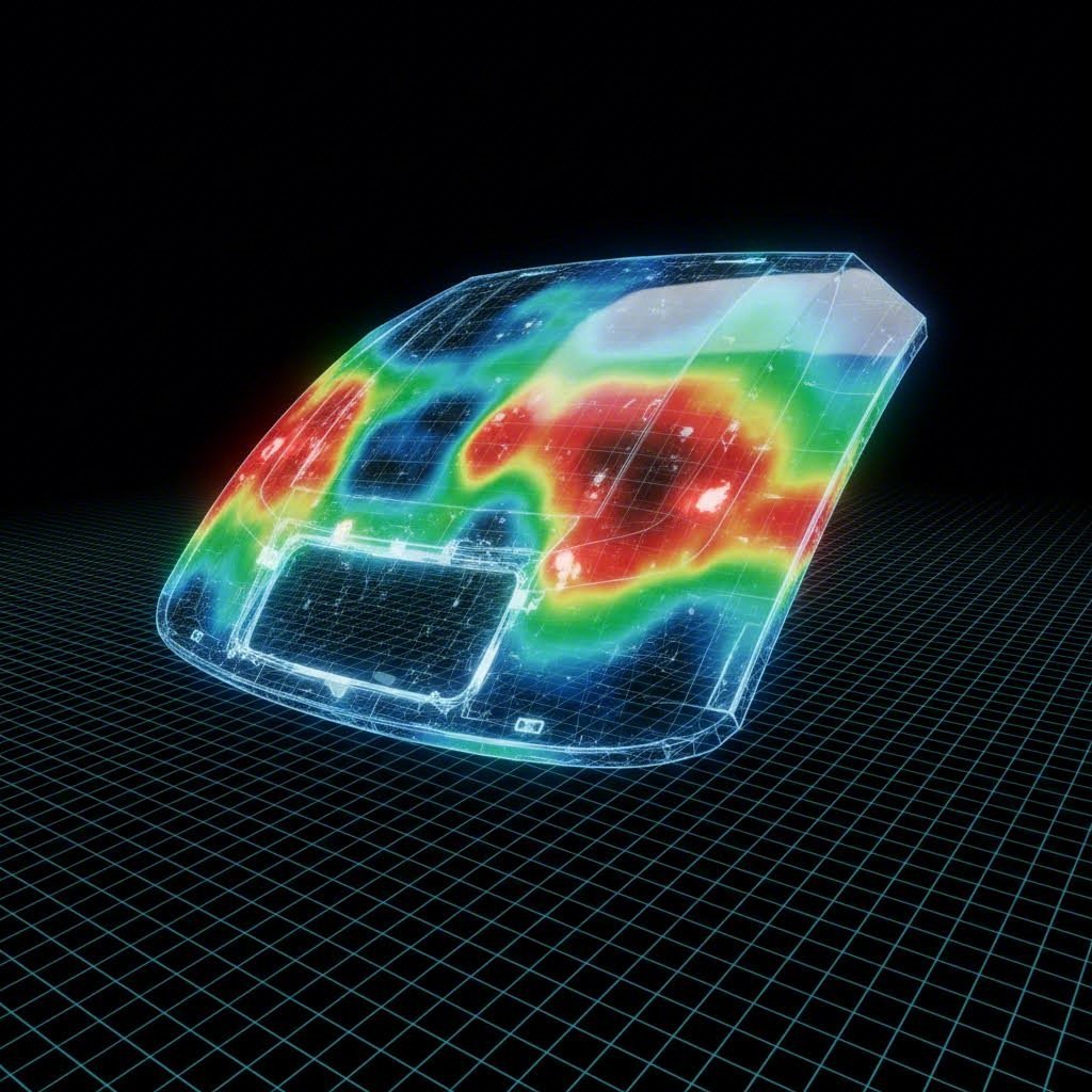
Surface Defects in Automotive Stamping: Diagnosis & Repair Guide Heat map visualization of stress distribution on a stamped automotive panel
TL;DR
Surface defects in automotive stamping are the primary driver of scrap rates and delayed production launches, categorized generally into Class A cosmetic defects (which compromise aesthetics) and structural defects (which compromise safety). Effective diagnosis requires distinguishing between static defects (caused by tooling contamination or damage) and dynamic defects (caused by process variables like flow, heat, and strain).
To achieve zero-defect manufacturing, engineers must optimize process variables—specifically Blank Holder Force (BHF), lubrication, and tool radii—while leveraging advanced detection methods. This guide covers the root causes of critical defects like orange peel, shock lines, and splits, offering actionable solutions from digital simulation to shop-floor maintenance.
Class A Cosmetic Defects (The "Brand Killers")
For outer skin panels such as hoods, doors, and fenders, even microscopic surface deviations can ruin the "Class A" finish required by OEMs. These defects do not affect part strength but create visible distortions after painting. Managing them requires precise control over material properties and strain distribution.
Orange Peel
Diagnosis: A rough, textured surface resembling the skin of a citrus fruit. It becomes highly visible after painting, scattering light effectively and dulling the finish.
Root Cause: This is primarily a material-level issue. It occurs when individual metal grains deform independently rather than collectively. Coarse-grained materials are more susceptible to this phenomenon during deep drawing. In some cases, excessive lubrication can also trap pockets of oil, creating a similar surface texture.
Solution:
- Material Selection: Switch to fine-grained sheet metal with tighter grain size control standards.
- Strain Management: Ensure the material is stretched enough to tauten the surface but not so much that it induces grain-level instability.
- Lubrication Control: Optimize lubricant viscosity and application quantity to prevent hydrostatic roughening.
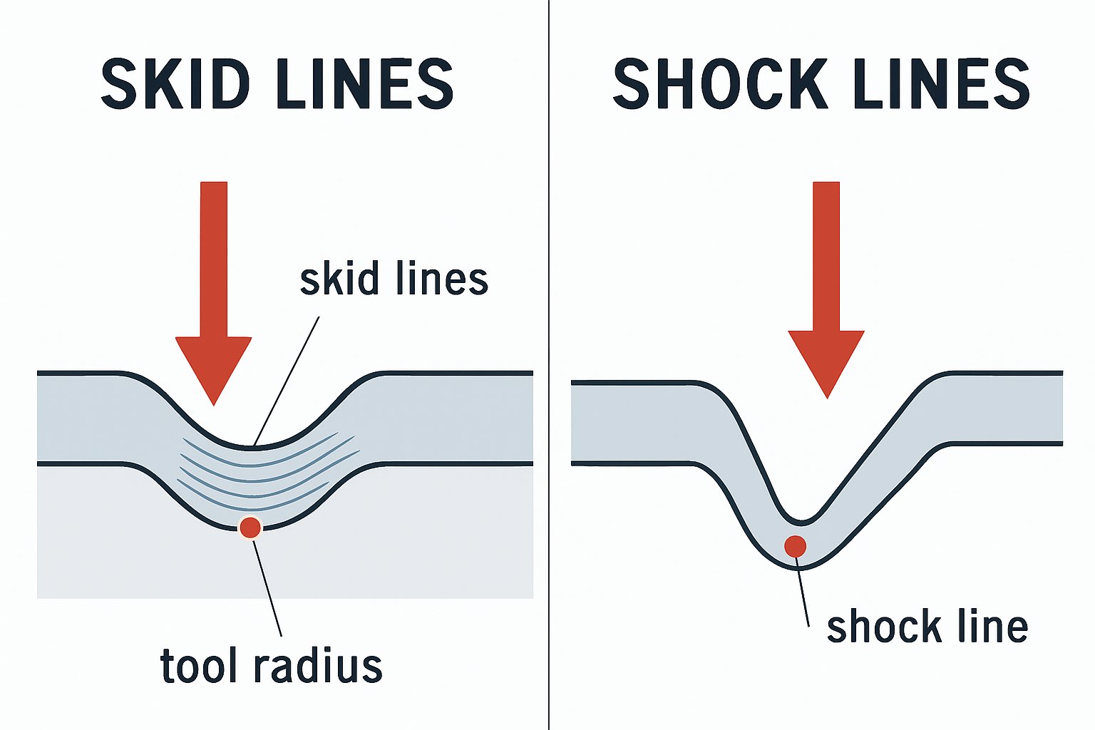
Skid Lines vs. Shock Lines
These two defects are often confused but have distinct mechanical origins. Differentiating them is critical for selecting the right fix.
- Skid Lines: Caused by the sheet metal physically sliding over a tool radius (like a die entry radius or a character line). This movement burnishes the surface, leaving a visible path. Fix: Polish tool radii to a mirror finish, apply high-performance lubricants, or adjust the addendum design to reduce metal movement over that specific radius.
- Shock Lines (or Impact Lines): Caused by strain hysteresis. When metal is bent over a radius and then unbent, the rapid change in strain can leave a visible line, even if no sliding occurred. This often happens near character lines. Fix: Increase the tool radius to reduce the severity of the bend-unbend cycle, or use simulation software to optimize the strain distribution during the design phase.
Surface Lows and Sink Marks
Diagnosis: Subtle depressions or "hollows" that are often invisible to the naked eye until the part is painted or stoned. They typically occur around door handle recesses or fuel filler doors.
Root Cause: These are often "Fall-in" defects caused by uneven strain distribution. When an area of high strain rate is surrounded by an area of low strain rate, the material relaxes unevenly, creating a low spot. Elastic recovery (springback) around complex geometries can also pull the surface inward.
Solution: Increase the Blank Holder Force (BHF) to generate sufficient tension across the panel, ensuring the material flows uniformly. Over-crowning the die face can also compensate for the expected relaxation.
Structural Integrity Defects (The "Part Killers")
Structural defects cause immediate part rejection because they compromise the physical integrity of the component. These are governed by the forming limit diagram (FLD) and the balance between tensile and compressive stresses.
Splits and Cracks
Diagnosis: Visible tears in the metal, ranging from hairline fractures to catastrophic splits. These typically occur in areas of high thinning, such as deep draw corners.
Mechanism: The material has exceeded its tensile strength limits. This is a dynamic defect often caused by excessive friction, insufficient material ductility (n-value), or aggressive die geometry.
Corrective Actions:
- Reduce BHF: Lower the blank holder force to allow material to flow more freely into the die cavity.
- Lubrication: Apply higher-performance lubricants or install active lubrication systems at critical friction points.
- Radius Optimization: Increase the die entry radius. A sharp radius acts like a brake, preventing material flow and causing it to stretch until failure.
Wrinkling
Diagnosis: Wavy, buckled metal, usually found in the flange area or tapered walls. Unlike splits, wrinkles are caused by compressive instability.
Mechanism: When metal is compressed tangentially (squeezed together), it tends to buckle out of plane if not constrained. This is common in tapered walls where there is excess material.
Corrective Actions:
- Increase BHF: Apply more pressure to the flange to physically suppress the buckling.
- Use Draw Beads: Install draw beads to restrict material flow and increase tension in the wall, pulling out the loose material that causes wrinkles.
- Note the Trade-off: Increasing BHF to fix wrinkles increases the risk of splits. The process window is the safe zone between these two failure modes.
Tooling & Process-Induced Defects
Not all defects come from material flow; many are imprints of the tool's condition or the stamping environment. Distinguishing between static and dynamic sources is the first step in troubleshooting.
Static vs. Dynamic Defects
| Defect Type | Characteristics | Common Causes | Primary Solutions |
|---|---|---|---|
| Static Defects | Repeatable, identical marks in the exact same location on every part. | Dirt, metal shavings (slugs), damaged die surfaces, or contamination on the tool face. | Clean the die sets; establish strict die maintenance schedules; polish tool surfaces. |
| Dynamic Defects | Process-dependent; severity may fluctuate with speed or heat. | Friction changes, heat buildup, galling (adhesive wear), or unstable press dynamics. | Adjust press speed; improve lubrication; apply PVD coatings (like TiCN) to tools to prevent galling. |
Galling and Burrs
Galling (or adhesive wear) occurs when the sheet metal fuses microscopically to the tool steel due to high pressure and heat, tearing chunks of material away. This leaves deep scratches and destroys the tool surface. It is prevalent in high-strength steel and aluminum stamping. The solution involves using advanced PVD tool coatings and ensuring chemical compatibility between the lubricant and the workpiece.
Burrs are sharp, raised edges along the trim line. They are almost always caused by improper die clearance. If the gap between the punch and die is too large (typically >10-15% of material thickness), the metal tears rather than shears cleanly. If too tight, it requires excessive force.
Managing these variables requires robust equipment and precise engineering. For manufacturers seeking to mitigate these risks from the start, partnering with a capable fabricator is essential. Shaoyi Metal Technology specializes in bridging this gap, leveraging IATF 16949-certified precision and press capabilities up to 600 tons to deliver critical components like control arms with strict adherence to OEM surface standards.
Detection & Quality Control Methods
Modern automotive standards have moved beyond simple visual inspection. Finding a defect is useful, but predicting it is transformative.
Manual vs. Digital Stoning
Manual Stoning: The traditional method involves rubbing a flat abrasive stone across the stamped panel. High spots (burrs, peaks) are abraded, while low spots remain untouched, creating a visual contrast map. While effective, it is labor-intensive and relies on operator skill.
Digital Stoning: This refers to using simulation software (like AutoForm) or optical scanning data to generate a virtual map of surface defects. By emulating the physical stoning process in a digital environment, engineers can identify Class A defects before the tool is even cut. This shifts quality control from the "Tryout" phase to the "Design" phase, significantly reducing development time and cost.
Optical Measurement Systems
Automated systems use structured light (zebra striping) or laser scanning to measure surface topology to the micrometer. These systems provide objective, quantifiable data that can be fed back into the press control system. For example, if an optical system detects a trending "sink mark," the press line can automatically adjust the cushion pressure to compensate, creating a closed-loop quality control system.