 Small batches, high standards. Our rapid prototyping service makes validation faster and easier —

Prototype CNC Secrets: From First Cut To Production-Ready Parts
What Prototype CNC Machining Actually Means for Product Development
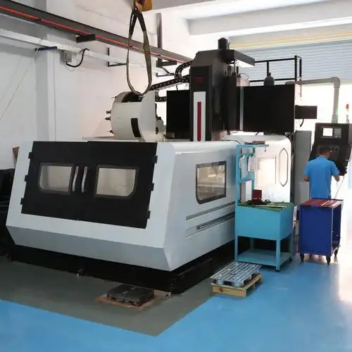
Before any product reaches the factory floor for mass production, it must pass through a critical validation phase. This is where prototype CNC machining becomes indispensable. But what exactly does this process involve, and why do engineering teams across industries rely on it so heavily?
At its core, prototype CNC refers to using computer-controlled machines to create functional test versions of parts directly from digital designs. Unlike additive methods that build layer by layer, this subtractive machining manufacturing process removes material from solid blocks—whether aluminum, steel, or engineering plastics—to achieve precise geometries. The result? A physical component made from production-grade materials that accurately represents your final product.
From Digital Design to Physical Reality
Imagine you've spent weeks perfecting a CAD model for a new automotive bracket or medical device housing. The design looks flawless on screen, but will it actually perform under real-world conditions? CNC prototyping bridges this gap by transforming your digital files into tangible parts you can hold, test, and evaluate.
The process begins with your CAD model and ends with a precision-machined component—often within days rather than weeks. This speed-to-part capability sets it apart from traditional tooling methods, which might require expensive molds or dies before producing even a single test piece. For engineers and procurement professionals exploring fast prototyping options, this distinction matters enormously when project timelines are tight.
CNC rapid prototyping offers superior accuracy, material versatility, and scalability compared to traditional methods, enabling quick iterations that reduce time-to-market and associated development costs.
Why Engineers Choose CNC for First-Run Parts
So why do engineers consistently choose this approach for initial part validation? The answer lies in several key advantages:
- Real material testing: Unlike a desktop CNC machine creating simple mockups, industrial prototype machining uses the same metals and plastics intended for final production
- Dimensional accuracy: Tight tolerances ensure the cnc prototype behaves exactly as designed
- Functional validation: Parts can be assembled, stress-tested, and evaluated in actual operating conditions
- Design iteration speed: Modifications can be implemented and re-machined within days
The growing demand for these capabilities spans multiple sectors. Automotive manufacturers use CNC prototyping to validate chassis components before committing to production tooling. Aerospace engineers rely on it for flight-critical parts requiring exceptional precision. Medical device companies leverage the technology to test implants and surgical instruments with biocompatible materials. Consumer electronics firms prototype enclosures and internal mechanisms to verify fit and function.
Understanding the fundamental difference between prototyping and production runs helps clarify when this approach delivers maximum value. Prototyping prioritizes speed and design validation over per-unit economics. You're investing in knowledge—confirming that your design works before scaling up. Production runs, by contrast, optimize for volume efficiency and cost-per-part. The insights gained through thorough cnc prototyping directly inform those production decisions, reducing costly errors downstream.
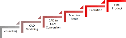
The Complete CNC Prototyping Workflow Explained
Now that you understand what prototype CNC machining delivers, you're probably wondering: what actually happens after you submit your design? The journey from digital file to finished part involves several carefully orchestrated stages—each with specific checkpoints that determine whether your project stays on schedule or encounters costly delays.
Unlike sending a document to a printer, cnc machining prototyping requires human expertise at every step. Engineers review your geometry, programmers optimize cutting paths, and quality specialists verify every critical dimension. Let's walk through this process so you know exactly what to expect.
The Five Stages of CNC Prototype Production
Whether you're ordering a single validation part or a small batch for functional testing, every cnc machining prototype follows this fundamental sequence:
- Design Review and DFM Feedback: Your CAD file undergoes manufacturability analysis. Engineers examine wall thicknesses, internal corner radii, hole depths, and feature accessibility. They'll flag any geometry that's impossible or impractical to machine—like internal corners sharper than available tool radii or pockets too deep for stable cnc cutting. This design for machining consultation often saves days of rework later.
- Material Selection and Procurement: Based on your application requirements, you'll confirm the stock material. This decision affects everything from cutting speeds to achievable tolerances. Some materials ship from existing inventory; specialty alloys may require procurement time.
- Toolpath Programming: CAM programmers translate your geometry into machine instructions. They select appropriate tools, determine optimal cutting strategies, and generate the G-code that controls every movement. Complex parts might require multiple setups and dozens of individual operations.
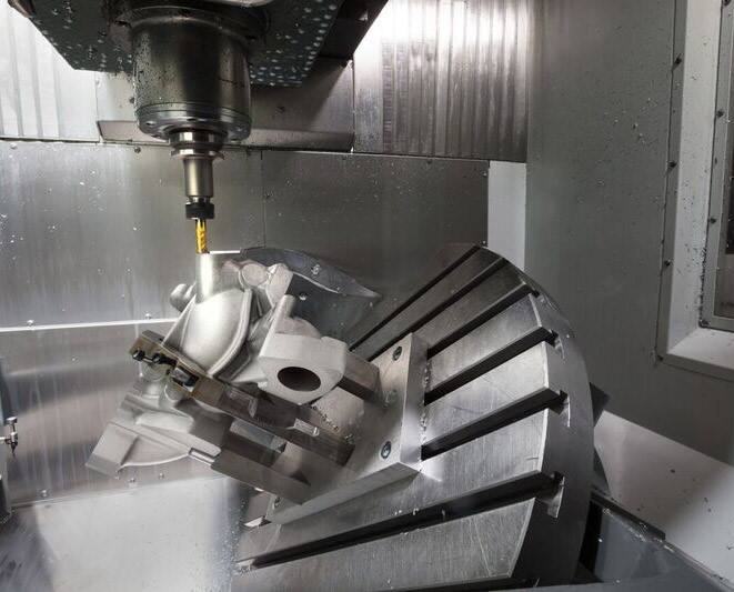
- Machining Operations: Your part takes physical form. Depending on complexity, this might involve cnc milling, turning, or both. Multi-axis machines can complete intricate geometries in fewer setups, reducing handling time and maintaining tighter tolerances.
- Post-Processing and Inspection: After machining, parts may require deburring, surface finishing, or secondary operations like threading or heat treatment. Quality technicians then verify critical dimensions against your specifications before shipping.
What Happens After You Submit Your CAD File
The file format you provide directly impacts how smoothly your project progresses. CNC shops work best with solid model formats that preserve accurate geometric data:
- STEP (.stp, .step): The universal standard for cnc prototype machining—maintains full geometry across different software platforms
- IGES (.igs, .iges): Widely compatible, though occasionally loses some surface detail during translation
- Parasolid (.x_t, .x_b): Excellent for complex assemblies with precise surface definitions
- Native CAD files: SolidWorks, Inventor, or Fusion 360 files work when your vendor supports them
Avoid mesh-based formats like STL for cnc machining milling operations. These files approximate curves with tiny triangles—acceptable for 3D printing but problematic for precision machining where smooth surfaces matter.
Why does the design-for-manufacturability review matter so much before cnc cutting begins? Consider this scenario: you've designed a housing with 0.5mm internal corner radii. The smallest practical end mill for that material might be 1mm diameter, creating 0.5mm corner radii at minimum. If your mating component requires sharper corners, you'll discover the problem only after machining—or worse, during assembly. A thorough DFM review catches these issues when changes cost nothing but a few CAD adjustments.
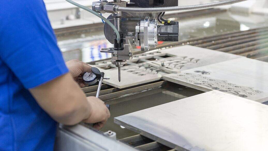
Throughout the process, tolerance verification occurs at multiple checkpoints. Critical dimensions get measured during machining to catch drift before it compounds. First-article inspection documents every specification before batch production continues. For cnc prototype machining projects, this quality discipline ensures your test parts accurately represent what production components will deliver.
With your workflow knowledge established, the next critical decision awaits: selecting the right material for your specific testing requirements.
Material Selection Guide for CNC Prototype Projects
Choosing the right material can make or break your prototype project. Select wisely, and you'll get accurate test results that translate directly to production. Choose poorly, and you might validate a design that fails under real-world conditions—or spend far more than necessary on materials that exceed your actual requirements.
The good news? Prototype CNC machining offers remarkable material flexibility. From lightweight aluminum alloys to high-performance engineering plastics, you can match your stock material precisely to your testing objectives. Let's explore your options.
Metals That Machine Best for Prototypes
When your prototype must replicate the mechanical properties of production parts, metals deliver unmatched performance. Here's what you need to know about the most commonly machined options:
| Material | Machinability Rating | Typical Tolerances | Cost Tier | Best Applications |
|---|---|---|---|---|
| Aluminum 6061 | Excellent | ±0.025mm | Low | General prototyping, enclosures, brackets, fixtures |
| Aluminum 7075 | Very Good | ±0.025mm | Medium | Aerospace components, high-stress structural parts |
| Stainless Steel 304 | Moderate | ±0.05mm | Medium | Corrosion-resistant parts, food/medical equipment |
| Stainless Steel 316 | Moderate | ±0.05mm | Medium-High | Marine, chemical processing, surgical instruments |
| Brass C360 | Excellent | ±0.025mm | Medium | Electrical connectors, decorative hardware, fittings |
| Titanium Grade 5 | Difficult | ±0.05mm | High | Aerospace, medical implants, high-strength/low-weight parts |
Aluminum alloys dominate prototype CNC work for good reason. Both 6061 and 7075 machine beautifully, accept anodizing well, and cost significantly less than steel or titanium. The 6061 grade handles most general applications—think housings, mounting brackets, and test fixtures. When you need higher strength-to-weight ratios, 7075 delivers aerospace-grade performance at a modest cost premium.
Stainless steels require more machining time and tool wear, which increases costs. However, they're essential when corrosion resistance matters. Medical device prototypes, food processing components, and marine applications often demand stainless—even at the prototype stage—to ensure valid testing.
Brass sheet metal and bar stock machine exceptionally well, producing smooth finishes with minimal effort. Beyond decorative applications, brass excels for electrical components where conductivity matters. Its natural lubricity also makes it ideal for bushings and wear surfaces.
Titanium sits at the premium end. It's challenging to machine, requires specialized tooling, and costs considerably more than aluminum. But for aerospace prototypes, medical implants, or any application demanding exceptional strength-to-weight ratios with biocompatibility, titanium remains irreplaceable.
Engineering Plastics for Functional Testing
Not every prototype needs metal. Engineering plastics offer distinct advantages: lighter weight, lower material costs, faster machining, and properties that metals simply cannot match—like electrical insulation and chemical resistance.
| Material | Machinability Rating | Typical Tolerances | Cost Tier | Best Applications |
|---|---|---|---|---|
| ABS | Excellent | ±0.1mm | Low | Consumer product housings, prototypes for injection molding |
| Delrin (Acetal Homopolymer) | Excellent | ±0.05mm | Medium | Gears, bearings, snap-fit connectors, high-stress parts |
| Acetal Copolymer | Excellent | ±0.05mm | Low-Medium | Valves, pumps, food-contact components |
| Nylon (PA6/PA66) | Good | ±0.1mm | Low-Medium | Wear parts, bushings, structural components |
| Polycarbonate | Good | ±0.1mm | Medium | Transparent covers, impact-resistant housings, optical parts |
ABS plastic sheet stock represents the workhorse of plastic prototyping. It machines cleanly, costs little, and closely mimics the properties of injection-molded consumer products. If you're validating a design that will eventually be molded, ABS cnc machining gives you a functional preview at minimal expense.
Acetal vs Delrin—this distinction confuses many engineers. Here's the clarity you need: Delrin is DuPont's trade name for acetal homopolymer, while generic "acetal" typically refers to the copolymer version. According to material specialists, Delrin offers higher crystallinity, resulting in superior strength, stiffness, and fatigue resistance. It's the better choice for gears, bearings, and snap-fit connectors under repeated stress. Acetal copolymer, however, resists hot water and chemicals better, costs less, and avoids the centerline porosity issues that can affect Delrin in thick sections.
Nylon for machining presents some challenges—it absorbs moisture, which can affect dimensional stability. Pre-conditioning the material and controlling humidity during storage helps maintain accuracy. Despite this quirk, nylon's excellent wear resistance and toughness make it valuable for bushings, gears, and sliding components.
Polycarbonate sheet fills a unique niche: when you need transparency combined with impact resistance. Unlike acrylic, polycarbonate won't shatter under stress, making it ideal for safety covers, display windows, and optical prototypes. Its ability to withstand higher temperatures also expands application possibilities.
Metal vs Plastic: Making the Right Choice
When should you prototype in metal versus plastic? Consider these decision factors:
- Choose metal when: Your production part will be metal, you're testing structural loads, thermal conductivity matters, or you need the tightest possible tolerances
- Choose plastic when: You need electrical insulation, chemical resistance, lighter weight, lower cost, or when your production process will use injection molding
- Consider both: Some projects benefit from plastic prototypes for form/fit checks, followed by metal prototypes for functional validation
Material choice directly impacts lead time and project cost. Aluminum sheet metal and common plastics typically ship from stock, enabling rapid turnaround. Specialty alloys, specific titanium grades, or less common engineering plastics may require procurement delays. Your prototype partner should clarify material availability during the quoting process.
With your material selected, understanding how each option—and the alternatives to CNC—affects your project economics becomes the next critical consideration.
CNC Prototyping vs 3D Printing and Other Methods
You've selected your material and understand the CNC workflow. But here's a question worth asking: is prototype CNC machining actually the right approach for your specific project? Sometimes it absolutely is. Other times, alternative technologies deliver better results faster and at lower cost.
Making this choice correctly saves both time and budget. Let's compare your options objectively so you can match the right technology to each prototype iteration.
When CNC Beats 3D Printing
CNC machining and 3D printing represent fundamentally different approaches. One removes material from solid blocks; the other builds parts layer by layer. According to Fictiv's manufacturing analysis, CNC consistently outperforms additive methods in several critical scenarios:
- High precision requirements: When tolerances below ±0.1mm matter, machining delivers accuracy that most 3D printing processes cannot match
- Functional stress testing: Parts machined from solid material blocks exhibit superior strength compared to layer-built components susceptible to delamination
- Production-equivalent materials: Unlike 3D printing resin or thermoplastics, CNC uses the exact metals and engineering plastics your final product requires
- Surface finish quality: Machined surfaces typically require minimal post-processing, while printed parts often need sanding, coating, or secondary operations
However, 3D printing technologies have earned their place in product development for compelling reasons. SLA 3D printing excels at producing highly detailed prototypes with smooth surfaces—ideal for visual models and fit checks. SLS 3d printing creates functional nylon parts without support structures, enabling complex geometries impossible to machine. Print FDM methods offer the fastest, lowest-cost path to basic validation parts.
Even metal 3D printing has carved out specific niches. A metal 3d printer can produce internal geometries—like conformal cooling channels—that no cutting tool could reach. For specialized applications, metal 3D printing enables shapes that simply don't exist in the subtractive manufacturing world.
Choosing the Right Prototyping Technology
Rather than declaring one method superior, smart engineering teams select technologies based on what each prototype iteration actually needs to prove. Here's how the major options compare across key performance dimensions:
| Technology | Material Properties | Surface Finish | Tolerance Capability | Cost Per Part | Best Quantity Range | Typical Turnaround |
|---|---|---|---|---|---|---|
| CNC Machining | Excellent—production-grade metals and plastics | Very Good—Ra 0.8-3.2μm typical | ±0.025-0.1mm | Higher for singles, competitive at 5+ units | 1-500 parts | 1-5 days |
| SLA Printing | Moderate—rigid resins, limited durability | Excellent—smooth, fine details | ±0.1-0.2mm | Low to moderate | 1-50 parts | 1-3 days |
| SLS Printing | Good—nylon, functional thermoplastics | Moderate—grainy texture | ±0.1-0.3mm | Moderate | 1-200 parts | 2-5 days |
| FDM Printing | Basic—ABS, PLA, limited strength | Poor—visible layer lines | ±0.2-0.5mm | Very low | 1-20 parts | Hours to 2 days |
| Urethane Casting | Good—simulates production plastics | Good—replicates mold surface | ±0.15-0.25mm | Low per unit at 10+ parts | 10-100 parts | 5-15 days |
When NOT to Use CNC Prototyping
Here's what most guides won't tell you: prototype CNC isn't always the answer. Recognizing when to choose alternatives prevents wasted time and budget:
- Very early concept validation: If you're simply checking basic form and fit—not material properties—a quick FDM print at a fraction of the cost makes more sense
- Highly organic geometries: Sculpted, flowing shapes with minimal flat surfaces often machine inefficiently, requiring extensive setup time and tool changes
- Internal lattice structures: Weight-optimized designs with hollow interiors can't be machined at all—they require additive processes
- Extreme budget constraints on single parts: One-off CNC prototypes carry significant setup costs that 3D printing avoids entirely
- Transparent or flexible requirements: Clear SLA printing and flexible TPU printing outperform machining for these specific material needs
The Hybrid Approach: Best of Both Worlds
The most effective prototyping strategies often combine multiple technologies across development phases. As manufacturing experts note, hybrid approaches leverage each method's strengths while minimizing their limitations:
Phase 1 - Concept validation: Use FDM or SLA printing for rapid, low-cost form checks. Iterate daily if needed. Material properties don't matter yet—you're testing shapes and basic fit.
Phase 2 - Functional prototyping: Switch to CNC machining when you need real material performance. Test mechanical loads, thermal behavior, and assembly with production-equivalent parts.
Phase 3 - Pre-production verification: For plastic parts heading to injection molding, urethane casting can bridge the gap—producing small batches in materials that closely simulate final production plastics.
Some projects even combine technologies within a single part. A 3D-printed component can receive CNC post-machining on critical surfaces requiring tight tolerances. This hybrid finishing achieves the geometric freedom of additive manufacturing with the precision of subtractive processes.
Understanding when each technology delivers maximum value lets you allocate your prototyping budget strategically. Speaking of budget—let's examine exactly what drives CNC prototype costs and how to optimize your investment.
Understanding CNC Prototype Pricing and Cost Factors
So, how much does it actually cost to get a metal part made? This question tops the list for engineers and procurement teams evaluating prototype CNC options. Unlike off-the-shelf components with fixed prices, machined parts pricing depends on a complex interplay of factors—some you control, others dictated by physics and economics.
The good news? Understanding these cost drivers gives you real leverage. Smart design choices and strategic ordering can cut your prototype budget significantly without sacrificing the quality or accuracy your testing demands. Let's break down exactly what you're paying for.
What Drives CNC Prototype Costs
Every quote you receive reflects a simple formula: Total Cost = Material Cost + (Machining Time × Machine Rate) + Setup Cost + Finishing Cost. But within each component, multiple variables affect the final number. Here are the primary factors that determine what you'll pay for cnc parts:
- Material type and volume: Raw material prices vary dramatically—aluminum costs far less than titanium, and plastics generally undercut metals. Beyond purchase price, material machinability matters enormously. Harder materials like stainless steel require slower cutting speeds, more frequent tool changes, and generate greater tool wear. A part that takes 30 minutes to machine in aluminum might require 90 minutes in titanium, tripling your machining costs regardless of material price differences.
- Geometric complexity: Complex shapes demand more machining time. Deep pockets, thin walls, tight internal corners, and features requiring 5-axis access all increase cycle time. Each tool change adds minutes; each additional setup multiplies handling time. Simple geometries that a 3-axis mill completes in one setup will always cost less than intricate parts requiring multiple orientations and specialized cutters.
- Tolerance requirements: Tighter tolerances mean slower cutting speeds, additional inspection time, and higher scrap risk. General tolerances (±0.1mm) cost significantly less than precision tolerances (±0.025mm). According to RapidDirect's cost analysis, ultra-tight tolerances and mirror finishes can double machining time compared to standard specifications.
- Surface finish specifications: An as-machined surface costs nothing extra. Bead blasting adds a modest fee. Anodizing, powder coating, polishing, or electroplating each introduce additional processing steps, labor, and materials. For metal machining parts requiring cosmetic finishes, these post-processing costs can rival the machining itself.
- Quantity: This single factor often creates the biggest per-unit price swings. Setup, programming, and fixturing costs remain fixed whether you order one part or fifty. Spread across a larger batch, the per-unit impact shrinks dramatically.
- Lead time urgency: Standard production timelines of 7-10 days keep costs manageable. Rush orders requiring 1-3 day delivery force overtime labor, schedule disruptions, and machine priority changes—often adding 25-50% premiums to your quote.
The Setup Cost Reality
Here's where prototype economics get interesting. Setup costs—including CAM programming, fixture preparation, tool selection, and first-article verification—represent fixed expenses that don't scale with part size or quantity. This reality profoundly impacts cnc machining parts pricing:
| Quantity | Estimated Setup Cost | Setup Cost Per Unit | Machining Per Unit | Total Per Unit |
|---|---|---|---|---|
| 1 part | $300 | $300.00 | $45 | $345.00 |
| 5 parts | $300 | $60.00 | $45 | $105.00 |
| 25 parts | $300 | $12.00 | $45 | $57.00 |
| 100 parts | $300 | $3.00 | $45 | $48.00 |
Notice how the unit price drops by over 85% between ordering one part versus twenty-five? This explains why prototype machining services often recommend slightly higher quantities when budget allows. Even ordering three or five parts instead of one can meaningfully reduce your effective cost per unit while providing backup samples for destructive testing.
How to Reduce Your Per-Part Price
You're not powerless against these cost drivers. Strategic design and ordering decisions can slash your prototype budget without compromising functionality. According to manufacturing cost experts, up to 80% of production cost gets locked in during the design phase. Here's how to keep costs under control:
- Increase internal corner radii: Sharp internal corners require tiny end mills that cut slowly and wear quickly. Designing radii at least 1.5x the pocket depth allows larger, faster, more durable tools. This single change often reduces machining time by 20-40%.
- Limit pocket depth: Optimal performance occurs when pocket depth stays within 2-3x the tool diameter. Deeper pockets require specialized long-reach tools, reduced cutting speeds, and sometimes multiple passes—all adding cost.
- Relax non-critical tolerances: Apply tight tolerances only to functional mating surfaces. General tolerances on non-critical dimensions avoid slow finishing passes and reduce inspection time. A drawing with one or two tight callouts costs far less than one demanding precision everywhere.
- Avoid thin walls: Walls thinner than 1mm (for metals) or 1.5mm (for plastics) require delicate machining at reduced speeds to prevent vibration and deformation. Thicker walls machine faster and cost less.
- Design for standard tooling: Use common drill sizes, standard thread pitches, and radii that match available end mill diameters. Custom or unusual features force shops to source specialized tools, adding cost and lead time.
- Minimize setups: Parts requiring machining from multiple sides need repositioning, which adds handling time and can introduce alignment errors. Design features accessible from one or two orientations when possible.
- Choose machinable materials: When performance requirements allow, aluminum alloys and common plastics like ABS and Delrin machine faster with less tool wear than stainless steel or titanium. The material cost difference is often dwarfed by machining time savings.
Cost Optimization Across Prototype Iterations
Smart prototype budgeting extends beyond individual parts to your entire development cycle. Consider structuring iterations strategically:
First iteration: Focus on validating basic geometry and fit. Use cost-effective aluminum or ABS. Accept standard tolerances. Skip cosmetic finishing. Get parts fast and cheap to confirm your design direction.
Second iteration: Incorporate learnings and tighten critical dimensions. If your production material differs from your first prototype, switch now to validate material-specific behavior.
Final validation: Apply production-equivalent specifications—final material, required tolerances, specified surface finishes. This pre-production prototype should match what manufacturing will deliver.
This phased approach from custom manufacturing services prevents wasting precision machining budget on designs that will change anyway. Early prototypes test concepts; later ones validate production readiness.
Understanding cost factors is essential, but so is knowing whether your parts will actually meet specification. Next, we'll examine what tolerances you can realistically achieve and how quality control validates your prototype's accuracy.
Tolerances and Quality Standards for Prototype Parts
You've selected your material, understood the costs, and chosen CNC over alternatives. Now comes a critical question: how precise will your prototype actually be? And equally important—how do you verify that precision before committing to production tooling?
Tolerance expectations and quality testing for cnc machined parts often get overlooked during project planning. Yet these factors directly determine whether your prototype delivers valid test data or misleads your development decisions. Let's establish realistic expectations and the inspection methods that validate them.
Achievable Tolerances in Prototype Machining
Not all features achieve the same precision. Holes, slots, flat surfaces, and threads each present different machining challenges—and your tolerance expectations should reflect these realities. Material properties further complicate the picture: metals generally hold tighter tolerances than plastics, which can deflect under cutting forces or shift with temperature and humidity changes.
According to HLH Rapid's tolerance guide, standard cnc milled parts typically achieve ISO 2768-1 Medium tolerances—approximately ±0.13mm (±0.005") for most linear dimensions. High-precision work can reach ±0.025mm (±0.001"), while specialized applications occasionally demand tolerances as tight as ±0.005mm (±0.0002").
Here's what you can realistically expect across different feature types and materials:
| Feature Type | Aluminum/Brass | Stainless Steel | Titanium | Engineering Plastics |
|---|---|---|---|---|
| Drilled Holes | ±0.025mm | ±0.05mm | ±0.05mm | ±0.1mm |
| Reamed Holes | ±0.013mm | ±0.025mm | ±0.025mm | ±0.05mm |
| Milled Slots | ±0.025mm | ±0.05mm | ±0.075mm | ±0.1mm |
| Flat Surfaces | ±0.025mm | ±0.05mm | ±0.05mm | ±0.1mm |
| Threads | Class 2B/6H typical | Class 2B/6H typical | Class 2B/6H typical | Class 2B/6H typical |
| Profile Tolerance | ±0.05mm | ±0.075mm | ±0.1mm | ±0.15mm |
When should you specify tighter tolerances? Only when assembly fit, mechanical function, or sealing surfaces genuinely require them. Over-tolerancing non-critical features inflates costs without improving part performance. Reserve precision prototyping machining specifications for dimensions that actually affect how your part functions.
Quality Control That Validates Your Design
Machining to tolerance means nothing without verification. Quality testing for cnc machined parts involves multiple inspection methods, each suited to different measurement needs. A comprehensive quality control process catches deviations before parts ship—ensuring your machined metal parts perform exactly as your design intended.
Dimensional Verification Methods
- Coordinate Measuring Machines (CMM): The gold standard for dimensional inspection. CMM probes map part geometry with micron-level accuracy, comparing actual dimensions against CAD models. Critical for verifying hole positions, surface profiles, and geometric tolerances on cnc milling parts.
- Optical Comparators: Project magnified part silhouettes onto screens for quick profile verification. Ideal for checking edge contours and 2D features on milled parts.
- Micrometers and Calipers: Handheld instruments for basic dimensional checks. Fast and effective for verifying external dimensions, hole diameters, and feature depths.
- Height Gauges: Measure vertical dimensions and step heights with high accuracy. Essential for validating machined surfaces and feature positions.
Surface Roughness Testing
Surface finish affects both function and appearance. Profilometers measure surface roughness (Ra values) to verify finish specifications. Standard as-machined surfaces typically achieve Ra 1.6-3.2μm. Finishing operations like polishing can reach Ra 0.4μm or better when required.
Statistical Process Control for Prototypes
You might think SPC only applies to high-volume production. But even prototype quantities benefit from statistical thinking. When machining multiple cnc milling parts, tracking dimensional trends across the batch reveals whether your process is stable or drifting. This data proves invaluable when scaling to production—you'll already understand your process capability.
First-article inspection documents become particularly important for precision prototyping machining. These comprehensive measurement reports verify every critical dimension on initial parts before batch production continues, catching systematic errors while correction remains simple.
Surface Finish Options and Their Impact
The surface finish you specify affects more than aesthetics—it influences functional testing validity. According to Protolabs' finishing guide, these common options serve different purposes:
- As-machined: Shows tool marks but costs nothing extra. Suitable when appearance doesn't matter or when you need to evaluate machining quality directly.
- Bead blasted: Creates uniform matte texture, hiding tool marks. Ideal for prototypes requiring non-reflective surfaces or improved grip.
- Anodized (Type II/III): Adds corrosion resistance, wear resistance, and color options to aluminum. Essential when testing parts in corrosive environments or when color-coding functional prototypes.
- Passivated: Enhances corrosion resistance on stainless steel without changing appearance. Critical for medical or food-contact prototypes.
- Powder coated: Provides durable colored finishes for prototypes requiring production-equivalent appearance.
When functional testing requires production-equivalent surfaces, specify finishes matching your production intent. Testing anodized prototypes when your production parts will be powder coated may yield misleading results—different finishes affect dimensions, friction, and surface hardness.
With tolerance expectations set and quality verification understood, you're well-positioned to avoid the common pitfalls that derail prototype projects. Let's examine these mistakes and their prevention strategies next.
Common CNC Prototype Mistakes and How to Avoid Them
You've done the hard work—selected materials, understood tolerances, and chosen the right manufacturing approach. Yet even experienced engineers stumble into predictable traps that delay delivery, inflate costs, or produce parts that fail to validate their designs. The frustrating part? Most of these mistakes are entirely preventable.
What separates successful prototype CNC projects from troubled ones often comes down to preparation and communication. According to Geomiq's manufacturing analysis, design decisions directly impact machining time, cost, and effort—meaning errors locked in during design become expensive to fix later. Let's examine the most common pitfalls and their solutions.
Design Errors That Delay Your Prototype
The mistakes that cause the biggest headaches typically occur before any cutting begins. These design-phase errors create ripple effects throughout production, forcing rework, requoting, or complete redesigns.
- Ignoring DFM feedback: When your manufacturing partner flags issues during design review, those concerns deserve serious attention. Sharp internal corners smaller than available tool radii, unsupported thin walls prone to vibration, or features requiring impossible tool access won't simply resolve themselves. Prevention: Treat DFM consultation as collaborative problem-solving, not criticism. Implement suggested changes before approving production—or discuss alternatives if functional requirements conflict with manufacturability.
- Over-tolerancing non-critical features: Applying ±0.025mm tolerances across every dimension when only mating surfaces require precision dramatically increases machining time and inspection effort. According to DFM specialists, this remains one of the most costly and common errors. Prevention: Specify tight tolerances only on functional features—bearing bores, sealing surfaces, assembly interfaces. Let non-critical dimensions default to standard machining tolerances of ±0.13mm.
- Designing features that can't be machined: Complex internal channels, undercuts requiring tool access from impossible angles, or internal corners sharper than any cutter can produce—these features work in CAD but fail on the machine. Prevention: Study cnc machine design fundamentals before finalizing geometry. Add internal corner radii at least 30% larger than your smallest tool radius. Ensure every feature has clear tool access.
- Insufficient wall thickness: Walls thinner than 0.8mm for metals or 1.5mm for plastics become susceptible to vibration, deflection, and warping during machining. The result? Dimensional inaccuracy, poor surface finish, or outright part failure. Prevention: Design walls with adequate stiffness. Maintain width-to-height ratios of at least 3:1 for unsupported walls.
- Excessive cavity depth: Deep pockets require long-reach tools prone to deflection and vibration. Cavities deeper than 4x their width push tooling limits and compromise accuracy. Prevention: Limit pocket depth to 3-4x the tool diameter when possible. For unavoidably deep features, accept wider tolerances or consider alternative manufacturing approaches.
Avoiding Costly Rework in First-Run Parts
Beyond design geometry, operational decisions frequently derail prototype projects. These process-related mistakes often prove more frustrating because they seem so avoidable in hindsight.
- Selecting wrong materials for testing conditions: Prototyping an aluminum bracket when your production part requires stainless steel means your stress testing yields misleading data. Similarly, using generic plastics when your application demands specific grades wastes validation effort. Prevention: Match prototype materials to production intent—especially for functional testing. Reserve material substitutions for early concept validation only.
- Underestimating lead times: Sample machining requires programming, setup, and quality verification regardless of part quantity. Expecting next-day delivery on complex cnc milling components sets everyone up for disappointment. Prevention: Build realistic timelines into project schedules. Standard prototype lead times run 5-10 business days; rush orders cost premium rates and still require minimum processing time.
- Poor file preparation: Submitting mesh-based STL files instead of solid STEP models, providing drawings with missing dimensions, or sending assemblies without identifying which components require machining—all create delays requiring clarification. Prevention: Submit clean solid models in STEP or Parasolid format. Include 2D drawings with complete tolerances and finish callouts. Clearly identify prototype components within larger assemblies.
- Unrealistic surface finish expectations: Every machined surface shows evidence of the cutting process. Expecting mirror finishes from as-machined parts, or being surprised by milling marks on unfinished surfaces, reflects misaligned expectations rather than manufacturing failures. Prevention: Specify required surface finishes explicitly. Understand that as-machined surfaces show tool paths—achieving smooth finishes requires secondary operations like polishing or bead blasting at additional cost.
- Failing to account for tool marks: Visible milling marks on cnc milled surfaces are normal machining artifacts, not defects. Their appearance varies with cutting strategy, material, and tool selection. Prevention: Accept visible tool marks on non-critical surfaces or specify finishing operations. Discuss acceptable surface appearance with your manufacturing partner before production begins.
Structuring Prototype Iterations Efficiently
The smartest prototype strategies treat iterations as distinct learning phases rather than identical repetitions. Each stage serves specific validation goals—and your approach should reflect those objectives.
Stage 1: Concept Validation
Focus purely on form and basic fit. Use cost-effective materials like aluminum or ABS. Accept standard tolerances. Skip cosmetic finishing entirely. The goal is confirming your fundamental geometry works—not perfecting production details. Expect to discover issues requiring design changes.
Stage 2: Functional Testing
Switch to production-equivalent materials. Tighten tolerances on critical features identified during concept validation. Begin evaluating mechanical performance, assembly sequences, and operational behavior. This is where cnc milling components prove whether your design actually functions under real conditions.
Stage 3: Pre-Production Verification
Apply full production specifications—final materials, required tolerances, specified surface finishes. These prototypes should be indistinguishable from production parts. Use this phase to validate manufacturing processes, confirm quality metrics, and finalize inspection criteria before committing to production tooling.
This phased approach prevents wasting precision machining budget on designs destined for revision. Early prototypes test concepts cheaply; later ones validate production readiness thoroughly.
Avoiding these common mistakes positions your project for success. But even with perfect preparation, choosing the right manufacturing partner determines whether that potential becomes reality. Next, we'll examine how to evaluate and select a CNC prototype service provider that matches your specific requirements.
Choosing the Right CNC Prototype Service Provider
You've designed your part, selected materials, and understand what tolerances you need. Now comes a decision that determines whether all that preparation translates into successful cnc prototypes—or frustrating delays and quality issues. Choosing the right prototype shop isn't simply about finding the lowest quote. It's about identifying a manufacturing partner whose capabilities, certifications, and communication style align with your project requirements.
The difference between an adequate vendor and an excellent one often becomes apparent only when problems arise. A responsive partner catches design issues before machining begins. A capable one delivers cnc machined prototypes that match specifications without endless revision cycles. Let's examine what separates the best cnc prototyping service providers from the rest.
What to Look for in a Prototype Partner
Evaluating potential manufacturing partners requires looking beyond surface-level marketing claims. These criteria distinguish providers capable of delivering quality results on schedule:
- Equipment capabilities (3-axis vs 5-axis): Three-axis mills handle straightforward geometries efficiently. But complex parts with angled features, undercuts, or compound curves demand 5 axis cnc machining services. Ask specifically what equipment a prototype machine shop operates—and whether their capacity matches your part complexity. Multi-axis capability reduces setups, improves accuracy, and enables geometries impossible on simpler machines.
- Material expertise: Not every shop machines every material equally well. Some specialize in aluminum and common plastics; others maintain tooling and expertise for titanium, Inconel, or exotic engineering polymers. Verify that your prospective partner has documented experience with your specific materials—especially if your project involves challenging alloys or high-performance plastics.
- Quality certifications: Certifications provide objective evidence of process discipline. ISO 9001 certification establishes baseline quality management practices. According to American Micro Industries' certification guide, these credentials verify that facilities maintain documented procedures, monitor performance metrics, and address nonconformities with corrective action—creating consistent, high-quality outcomes.
- Lead time reliability: Promises mean nothing without performance. Ask for references or case studies demonstrating on-time delivery records. The best online cnc machining services track and report their delivery metrics. A shop that quotes 5-day turnaround but consistently delivers in 8 days damages your project timeline and erodes trust.
- Communication responsiveness: How quickly does a vendor respond to quote requests? How thoroughly do they address technical questions? Early communication patterns predict ongoing collaboration quality. Providers offering proactive DFM feedback before quoting demonstrate engagement that translates to smoother production.
- Scaling capability from prototype to production: If your prototype succeeds, can this partner scale with you? Shops equipped only for low-volume work may lack capacity or process controls for production quantities. Partners offering seamless prototype-to-production transitions eliminate the costly learning curve of switching manufacturers mid-project.
Certifications That Matter for Your Industry
General quality certifications establish baseline competence, but regulated industries demand specialized credentials. Understanding which certifications apply to your application prevents costly qualification delays later.
Automotive applications require IATF 16949 certification—the global standard for automotive quality management. This certification extends ISO 9001 requirements with sector-specific controls for defect prevention, continuous improvement, and rigorous supplier oversight. According to industry certification experts, IATF 16949 compliance demonstrates robust product traceability and process control that leading automakers mandate from their supply chain.
Aerospace applications typically require AS9100 certification, which builds on ISO 9001 with additional requirements specific to aviation. This standard emphasizes risk management, stringent documentation, and product integrity control throughout complex supply chains. Many aerospace programs also require NADCAP accreditation for special processes like heat treating and nondestructive testing.
Medical device manufacturing falls under ISO 13485, the definitive quality standard for this field. Facilities seeking medical device work must implement detailed documentation practices, thorough quality checks, and effective complaint handling to satisfy both regulatory bodies and customer requirements.
Choosing a certified provider upfront—rather than discovering certification gaps after prototype approval—saves significant requalification effort when transitioning to production.
Evaluating Real-World Capabilities
When automotive prototype requirements demand both IATF 16949 certification and rapid turnaround, the vendor pool narrows considerably. Providers like Shaoyi Metal Technology exemplify what this combination looks like in practice—offering precision CNC machining for chassis assemblies and custom metal bushings backed by IATF 16949 certification and Statistical Process Control protocols. Their capability to deliver lead times as fast as one working day while maintaining automotive-grade quality demonstrates that speed and certification compliance aren't mutually exclusive.
What makes such providers valuable extends beyond certifications. The ability to scale seamlessly from rapid prototyping to mass production eliminates the risky vendor transition that derails many projects. When your prototype validates successfully, production ramps without requalifying a new manufacturer or transferring institutional knowledge.
As you evaluate potential partners, prioritize those demonstrating both the technical capabilities your parts require and the quality systems your industry demands. The right cnc prototyping service becomes an extension of your development team—accelerating iterations, catching issues early, and positioning your project for successful production scaling.
From Prototype Validation to Production Manufacturing
Your machined prototypes have passed functional testing. Dimensions check out. Assembly works smoothly. Stakeholders are excited. Now what? The transition from validated prototype to production manufacturing represents one of the most critical—and frequently mishandled—phases in product development.
Many teams assume that prototype approval means they're ready to scale. But according to UPTIVE Advanced Manufacturing's research, this assumption often leads to costly surprises when production quantities expose issues invisible at prototype scale. Understanding when and how to make this transition determines whether your launch stays on schedule or spirals into delays and budget overruns.
When Your Prototype Is Ready for Production
Not every successful prototype signals production readiness. Genuine readiness requires satisfying multiple criteria beyond basic functionality. Ask yourself these decision-point questions before committing to production tooling:
- Have you validated with production-equivalent materials? Prototype machined parts created in aluminum when production requires stainless steel haven't truly validated material behavior under operational conditions.
- Do critical tolerances match production specifications? Relaxed tolerances during rapid prototype machining may hide fit issues that emerge at tighter production specifications.
- Has functional testing replicated actual use conditions? Lab testing differs from field conditions. Ensure your machined prototypes have experienced realistic stress, temperature, and environmental exposure.
- Are supply chain elements confirmed? Production requires consistent material sourcing, secondary processes, and finishing operations. Verify availability before committing to volumes.
- Is design documentation complete? Production-ready drawings must include all tolerances, surface finishes, material callouts, and inspection criteria—not just the basics used for cnc rapid prototyping.
According to LS Manufacturing's prototyping guide, the most successful transitions occur when teams treat final validation prototypes as production trial runs—applying full specifications and quality controls even at low quantities.
Scaling Without Starting Over
Here's where strategic planning pays dividends. The worst-case scenario? Validating prototypes with one manufacturer, then scrambling to find a production partner—transferring drawings, requalifying processes, and rebuilding institutional knowledge from scratch. This vendor transition introduces risk, delays, and costs that compound quickly.
The most efficient prototype-to-production path maintains manufacturing continuity—keeping the partner who learned your design's nuances through prototype iterations engaged for production scaling.
This continuity principle explains why choosing the right rapid cnc prototyping partner matters so much upfront. Providers capable of scaling from single prototype machined parts to production volumes eliminate the risky handoff between development and manufacturing. They've already optimized toolpaths, verified material behavior, and established quality baselines during prototyping—knowledge that directly accelerates production ramp-up.
For automotive applications where this continuity proves especially valuable, partners like Shaoyi Metal Technology demonstrate what seamless scaling looks like in practice. Their capability to transition from rapid machining of chassis assemblies and custom metal bushings during prototyping directly into mass production—backed by IATF 16949 certification and Statistical Process Control—eliminates the requalification delays that plague manufacturer transitions.
How Prototype Learnings Inform Production Decisions
Every prototype iteration generates data that should inform your production approach. Smart teams capture and apply these learnings systematically:
- Dimensional trends: Which features consistently approached tolerance limits during machining for manufacturing? These may require process adjustments or tolerance revisions for production stability.
- Machining challenges: Features that caused tool deflection, chatter, or extended cycle times during prototyping will create the same issues at volume—only multiplied across thousands of parts.
- Material behavior: Did your chosen material machine predictably? Any warping, residual stress, or surface issues discovered during prototyping indicate production risks requiring mitigation.
- Inspection bottlenecks: Features requiring extensive verification time during prototyping become quality control chokepoints at production scale. Consider whether design modifications could simplify inspection.
This accumulated knowledge represents significant value. Discarding it by switching manufacturers means relearning these lessons—often through production defects rather than controlled prototype iterations.
Understanding Prototype-to-Production Economics
The relationship between prototype quantities and production economics deserves careful attention. Setup costs that dominate single-part pricing become negligible when amortized across thousands of units. But new cost factors emerge at volume:
| Cost Factor | Prototype Impact | Production Impact |
|---|---|---|
| Setup/Programming | Major cost driver | Negligible per unit |
| Material Cost | Moderate impact | Major cost driver |
| Cycle Time | Secondary concern | Critical for throughput |
| Tool Wear | Minimal consideration | Significant ongoing cost |
| Quality Control | Per-part inspection | Statistical sampling |
This shift explains why production optimization often involves revisiting designs that worked fine at prototype scale. Features acceptable when machining five parts may become uneconomical across five thousand. Production-focused DFM review—distinct from prototype DFM—identifies opportunities to reduce cycle time, extend tool life, and simplify fixturing for volume efficiency.
Your Next Steps Based on Project Stage
Where you are in your development journey determines your immediate priorities:
If you're just starting prototyping: Select a manufacturing partner with both rapid prototyping capability and production capacity. Establish this relationship before cutting your first part—the learning accumulated during prototyping becomes invaluable during production scaling.
If you're mid-iteration: Document everything. Track dimensional results, note machining challenges, and capture any design modifications. This data informs production decisions and helps new team members understand why current geometry evolved from earlier versions.
If prototypes are validated: Conduct a formal production readiness review. Verify that documentation is complete, supply chain is confirmed, and your manufacturing partner has capacity for your volume requirements. Address gaps before authorizing production—discoveries made after commitment become expensive corrections.
If you're evaluating partners for production transition: Prioritize providers demonstrating seamless rapid prototyping to mass production capability. Certifications like IATF 16949 for automotive or AS9100 for aerospace ensure quality systems appropriate for regulated industries. Lead time reliability and communication responsiveness observed during prototyping predict production partnership quality.
The journey from first cut to production-ready parts demands technical expertise, strategic planning, and the right manufacturing relationships. By applying the principles covered throughout this guide—from material selection through tolerance specification to vendor evaluation—you position your project for successful scaling. Your prototype CNC work isn't just about creating test parts; it's about building the knowledge foundation that makes production success possible.
Frequently Asked Questions About Prototype CNC Machining
1. What is a CNC prototype?
A CNC prototype is a functional test part created using computer-controlled machining from your CAD design. Unlike 3D printing that builds layer by layer, CNC prototyping uses subtractive manufacturing to remove material from solid blocks of production-grade metals or engineering plastics. This produces highly precise components with tight tolerances that accurately represent your final product's mechanical properties, enabling realistic functional testing before committing to production tooling.
2. How much does a CNC prototype cost?
CNC prototype costs typically range from $100 to $1,000+ per part depending on several factors: material type (aluminum costs less than titanium), geometric complexity, tolerance requirements, surface finish specifications, quantity ordered, and lead time urgency. Setup costs remain fixed regardless of quantity, so ordering 5-25 parts instead of one significantly reduces per-unit pricing. Simple aluminum prototypes start around $100-200, while complex metal parts with tight tolerances can exceed $1,000.
3. How long does CNC prototyping take?
Standard CNC prototype lead times run 5-10 business days from design approval to delivery. However, many specialized providers offer expedited services with turnaround as fast as 1-3 days for rush orders, though this typically adds 25-50% to the cost. The timeline includes design review, CAM programming, material procurement if needed, machining operations, post-processing, and quality inspection. Complex parts with multiple setups or specialty materials may require additional time.
4. When should I choose CNC machining over 3D printing for prototypes?
Choose CNC machining when you need production-equivalent material properties, tolerances below ±0.1mm, functional stress testing with real metals or engineering plastics, superior surface finishes, or quantities of 5+ parts where CNC becomes cost-competitive. Opt for 3D printing for early concept validation, organic geometries, internal lattice structures, single low-cost parts, or when transparent or flexible materials are required. Many successful projects use both technologies at different development stages.
5. What certifications should I look for in a CNC prototype service provider?
ISO 9001 certification establishes baseline quality management for general applications. Automotive projects require IATF 16949 certification, which mandates stringent defect prevention and process control. Aerospace applications need AS9100 certification with additional risk management requirements. Medical device manufacturing requires ISO 13485 compliance. Choosing a certified provider upfront prevents costly requalification delays when transitioning from prototyping to production manufacturing.