 Small batches, high standards. Our rapid prototyping service makes validation faster and easier —

Product Machining Decoded: From Raw Material To Precision Parts
What Product Machining Really Means for Modern Manufacturing
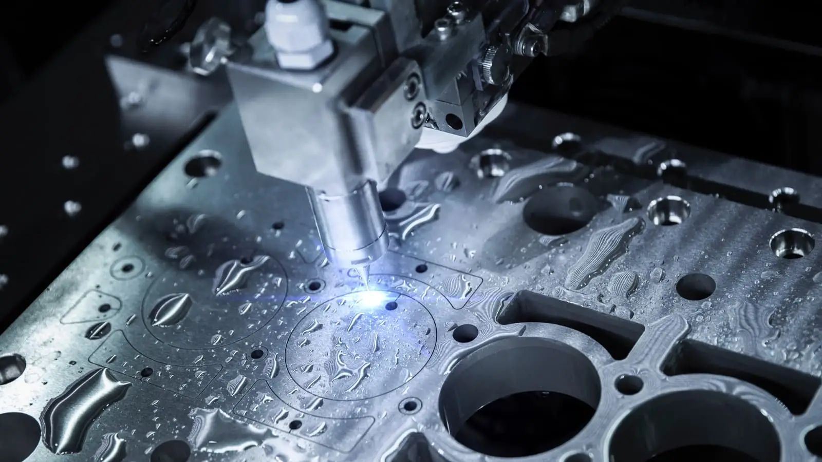
Ever wondered how raw metal blocks transform into the precise components inside your car engine or smartphone? The answer lies in product machining—a manufacturing approach that shapes our modern world in ways most people never see.
Product machining is a subtractive manufacturing process where material is systematically removed from a workpiece using cutting tools to create functional, market-ready components with precise specifications.
So what is machining in practical terms? Unlike 3D printing, which builds parts layer by layer, this process works in reverse. You start with more material than you need and strategically cut away everything that isn't your final product. Think of it like sculpting—except with spinning tools, computer control, and tolerances measured in thousandths of an inch.
The Subtractive Manufacturing Principle
The definition of machining centers on one fundamental concept: removal. Whether you're turning a steel rod on a lathe or milling aluminum on a CNC machine, you're always taking material away rather than adding it. This subtractive manufacturing approach offers distinct advantages that additive methods simply cannot match.
Consider material properties. When you machine a component from solid stock, you preserve the metal's original grain structure and mechanical properties. The part maintains consistent strength throughout because you haven't altered the material's fundamental characteristics. This matters tremendously for components facing high stress, extreme temperatures, or demanding performance requirements.
Machining is a process that also delivers superior surface finishes and tighter tolerances compared to most additive alternatives. While 3D-printed parts often require post-processing, machined components frequently come off the machine ready for assembly.
From Raw Material to Finished Product
Here's where product machining differs from general machining work. The machining meaning in a product context extends beyond simply cutting metal—it encompasses the entire journey from design intent to functional component.
When you define machining for manufacturing purposes, you're describing a systematic process designed to produce repeatable, quality-verified parts at scale. General machine shop work might focus on one-off repairs or custom pieces. Product machining, however, prioritizes:
- Consistent repeatability across production runs
- Design optimization for manufacturability
- Quality documentation meeting industry standards
- Scalability from prototype to mass production
This product-centric approach means every decision—from material selection to tool path programming—serves the ultimate goal of delivering functional components that perform reliably in their intended applications. Whether you're a designer exploring manufacturing options or an engineer optimizing existing processes, understanding this distinction helps you communicate more effectively with manufacturing partners and make better decisions for your projects.
Essential Machining Processes and When to Use Each
Now that you understand what product machining accomplishes, the next question becomes: which process should you use? Choosing among different machining types isn't about picking favorite equipment—it's about matching the right method to your specific product requirements. Let's break down the major machining processes and when each one makes the most sense for your components.
Rotational vs Linear Cutting Methods
All machining operations fall into two fundamental categories based on how cutting motion occurs. Understanding this distinction helps you quickly narrow down which processes suit your product geometry.
Rotational cutting methods involve either the workpiece spinning against a stationary tool or the tool rotating against a fixed workpiece. Machining turning operations represent the classic example—your cylindrical stock spins on a lathe while cutting tools shape the exterior and interior surfaces. This approach excels at producing shafts, bushings, pins, and any component with rotational symmetry.
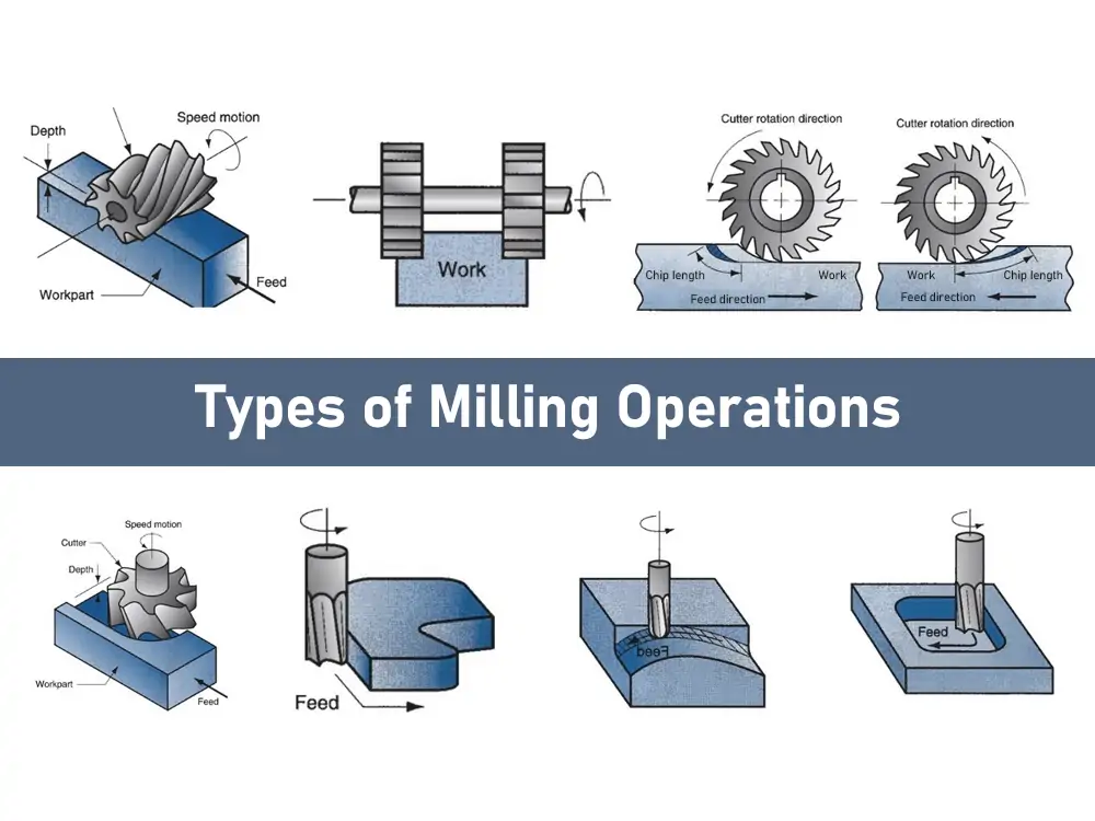
Milling machining flips the script. Here, multi-point cutting tools rotate at high speeds while the workpiece remains clamped to the table. Metal milling processes can create complex three-dimensional geometries, pockets, slots, and intricate surface features that turning simply cannot achieve. When your product needs flat surfaces, angular features, or compound curves, milling becomes your primary process.
Linear cutting methods move tools in straight paths through material. Sawing machining operations cut stock to length or create straight separations. Broaching pushes or pulls specialized tools through workpieces to create keyways, splines, or complex internal profiles in a single pass. These processes serve specific functions within broader shaping manufacturing workflows.
Matching Process to Product Geometry
Selecting the right machining processes starts with analyzing what your finished component actually needs. Ask yourself these questions:
- Does your part have rotational symmetry, or does it require complex multi-axis features?
- What tolerance levels must the finished component achieve?
- How critical is surface finish quality to product function?
- Does the part require internal features like holes, threads, or keyways?
Your answers guide process selection more effectively than starting with available equipment. A precision shaft with tight concentricity requirements points directly to turning. A housing with multiple mounting features and internal cavities demands milling. Most real-world products require combining several processes in sequence.
| Process Name | Best Product Applications | Typical Tolerances | Surface Finish Quality |
|---|---|---|---|
| Turning | Shafts, bushings, pins, cylindrical housings | ±0.001" to ±0.005" | 16-125 Ra microinches |
| Milling | Housings, brackets, plates, complex 3D parts | ±0.001" to ±0.005" | 32-125 Ra microinches |
| Drilling | Through holes, blind holes, bolt patterns | ±0.002" to ±0.005" | 63-250 Ra microinches |
| Grinding | Precision surfaces, hardened components, tight-tolerance features | ±0.0001" to ±0.001" | 4-32 Ra microinches |
| Sawing | Stock preparation, cutoff operations, straight separations | ±0.010" to ±0.030" | 125-500 Ra microinches |
| Broaching | Keyways, splines, internal gears, complex internal profiles | ±0.0005" to ±0.002" | 16-63 Ra microinches |
| EDM (Electrical Discharge Machining) | Hardened materials, intricate cavities, thin-wall features | ±0.0002" to ±0.001" | 8-125 Ra microinches |
Notice how grinding and EDM deliver the tightest tolerances and finest finishes—but they also require more time and cost per part. Sawing sits at the opposite end, providing rough cuts that prepare stock for subsequent precision operations. Most production sequences combine coarse processes for material removal with finishing processes for final specifications.
Drilling deserves special mention because virtually every machined product requires holes. Whether you're creating mounting points, fluid passages, or assembly features, drilling operations integrate into nearly every manufacturing workflow. Modern CNC machining centers often combine drilling, milling, and sometimes turning capabilities in single setups, reducing handling time and improving accuracy.
Understanding these machining processes empowers you to have more productive conversations with manufacturing partners. Instead of simply describing what your part looks like, you can discuss which operations make sense and why certain features might require specific approaches. This knowledge becomes even more valuable when you understand how CNC technology orchestrates these processes with digital precision.
Understanding CNC Technology and Digital Manufacturing Control
You've seen how different machining processes serve different product needs. But here's the question that ties everything together: how do modern machines execute these operations with such incredible precision? The answer is CNC technology—the digital brain that transforms your design files into physical reality.
So what is CNC, exactly? To define CNC simply: it stands for Computer Numerical Control. This technology translates digital design data into precise machine movements, controlling every cut, every rotation, and every tool change with accuracy measured in thousandths of an inch. If you've ever wondered what does CNC stand for in manufacturing, think of it as the bridge between your computer screen and the machine shop floor.
How Digital Designs Become Physical Products
The cnc machining process begins long before any cutting happens. It starts with a CAD file—your digital blueprint. Designers create these files using specialized software, defining every dimension, curve, hole, and angle of the finished component. Think of CAD as digital clay that you sculpt on screen until it perfectly matches your vision.
But CNC machines don't understand CAD files directly. They need step-by-step cutting instructions. This is where CAM (Computer-Aided Manufacturing) software enters the picture. CAM programs analyze your design and generate toolpaths—the exact routes cutting tools will follow to shape your material.
During this translation, CAM software makes critical decisions:
- Which cutting tools best suit each feature
- How fast tools should spin (spindle speed)
- How quickly tools should move through material (feed rate)
- What sequence of operations produces the best results
The output from this planning stage is G-code—the universal language that CNC machines understand. Understanding how does cnc machining work means recognizing that G-code contains every instruction the machine needs: where to move, how fast to travel, when to start cutting, and when to change tools.
The Role of G-Code in Precision Control
G-code might sound intimidating, but it's essentially a recipe. Each line tells the machine to perform a specific action. Some commands control movement along the X, Y, or Z axes. Others activate spindle rotation, engage coolant systems, or trigger automatic tool changes.
What makes CNC operations so powerful is their repeatability. Once you've proven a G-code program produces a good part, you can run it hundreds or thousands of times with identical results. The machine doesn't get tired, doesn't lose focus, and doesn't introduce human variability into the process.
Here's the complete cnc machining process from design file to finished component:
- CAD Design Creation — Engineers or designers create a 3D model defining all part geometry, dimensions, and tolerances using software like SolidWorks, Fusion 360, or similar programs.
- CAM Programming — Programmers import the CAD file into CAM software, select appropriate tools, and generate optimized toolpaths that minimize machining time while meeting quality requirements.
- G-Code Generation — CAM software outputs G-code files containing all machine instructions, customized for the specific CNC machine that will produce the part.
- Machine Setup — Operators load raw material (the workpiece) and secure it using appropriate workholding fixtures like vises, clamps, or custom jigs that prevent movement during cutting.
- Tool Loading — Required cutting tools are installed in the machine's tool magazine or turret. Many modern machines feature automatic tool changers holding 20, 40, or even more tools.
- Zero Point Setting — The machine establishes exactly where the workpiece sits in three-dimensional space, ensuring all programmed movements align perfectly with the actual material position.
- Program Execution — The CNC controller reads G-code line by line, directing motors and drives to move cutting tools along programmed paths while removing material precisely.
- In-Process Monitoring — Operators and automated systems watch for issues like tool wear, dimensional drift, or unexpected vibrations that might affect part quality.
- Finishing Operations — Parts undergo deburring, cleaning, and any required surface treatments to meet final specifications.
- Quality Verification — Inspection using calipers, micrometers, or coordinate measuring machines confirms dimensions match the original CAD design within specified tolerances.
Whats CNC's biggest advantage over manual machining? Consistency. Whether you need one prototype or ten thousand production parts, properly programmed CNC operations deliver the same precision every time. Modern machines routinely achieve tolerances of ±0.001 inches or tighter—precision that would be nearly impossible to maintain manually across large production runs.
This digital foundation also enables rapid iteration. Need to modify a feature? Update the CAD model, regenerate toolpaths, and the machine produces your revised design within hours. This flexibility makes CNC technology essential for modern product development, where designs evolve quickly and time-to-market pressures demand agile manufacturing capabilities.
Of course, achieving these capabilities depends on understanding what tolerances your products actually require—and how different processes deliver different levels of precision.
Precision Tolerances and Surface Finish Standards
You've learned how CNC technology delivers remarkable consistency—but how tight can those tolerances actually get? And when do you need precision machining versus standard tolerances? Understanding these specifications separates successful product launches from costly manufacturing headaches.
Here's the reality: while CNC machines are extremely precise, achieving absolute perfection is impossible. Every machined dimension will have some small variation from the original design. The question isn't whether variation exists—it's how much deviation your product can tolerate while still functioning correctly.
Tolerance Classes and Their Real-World Impact
What is precision machining compared to standard work? The difference comes down to allowable dimensional deviation. According to industry standards, tolerances are expressed as the maximum and minimum allowable dimensions—typically written as ±0.x mm. If a part falls outside these limits, it gets rejected.
The international standard ISO 2768 provides a practical framework, dividing tolerances into four classes:
- Fine (f) — Tightest general tolerances for precision machined components requiring close fits
- Medium (m) — Standard tolerances suitable for most commercial applications
- Coarse (c) — Relaxed tolerances for non-critical dimensions
- Very Coarse (v) — Loosest tolerances for rough or non-functional features
Most machine shops default to ISO 2768-1 Medium for milled and turned parts—generally around ±0.005" (0.13 mm). This standard tolerance handles the vast majority of commercial product requirements without adding unnecessary cost.
But what about high precision machining applications? Precision machines can achieve significantly tighter specifications:
| Tolerance Level | Typical Range | Common Applications | Cost Impact |
|---|---|---|---|
| Standard CNC | ±0.005" (0.13 mm) | General commercial parts, housings, brackets | Baseline |
| Precision CNC | ±0.001" (0.025 mm) | Aerospace components, automotive performance parts | 1.5-2x baseline |
| High Precision | ±0.0005" (0.0127 mm) | Medical devices, optical equipment | 2-3x baseline |
| Ultra-Precision | ±0.0002" (0.00508 mm) | Surgical implants, specialized instrumentation | 3-5x baseline |
Notice something important? Only about 1% of parts actually require tolerances in that ultra-precision range. And often, it's just specific features—not the entire component—that need ±0.001" or tighter. Over-tolerancing is one of the most common mistakes in product design, driving up costs without improving function.
Here's a practical tip: use tighter tolerances only on critical features affecting assembly, fit, or function. Keep non-critical dimensions at standard tolerances. A mounting bracket doesn't need the same precision as a hydraulic valve spool—design accordingly.
Precision cnc milling and turning processes can achieve these tight specifications, but the relationship between tolerance and cost is exponential, not linear. Each step tighter requires more careful setup, slower cutting speeds, additional inspection time, and often specialized tooling. The result? Significantly longer lead times and higher part costs.
Surface Finish Specifications Explained
Tolerances control dimensional accuracy, but surface finish determines how your parts feel, function, and perform. Surface roughness—measured as the average height of surface irregularities—directly impacts friction, wear resistance, sealing capability, and even aesthetic appearance.
The most common measurement is Ra (Roughness Average), typically expressed in micrometers (µm) or microinches (µin). Lower Ra values indicate smoother surfaces—think of it like thread count in fabric, where higher numbers mean finer texture.
What do different Ra values actually mean for your products?
- Ra 0.025 µm (1 µin) — Mirror-like finish, extremely smooth; used for optical components and precision bearing surfaces
- Ra 0.4-0.8 µm (16-32 µin) — Very smooth; suitable for hydraulic components and sealing surfaces
- Ra 1.6-3.2 µm (63-125 µin) — Standard machined finish; appropriate for most functional surfaces
- Ra 6.3-12.5 µm (250-500 µin) — Rougher finish; acceptable for non-contact surfaces and raw stock
Different machining processes naturally produce different surface finishes. Grinding achieves the smoothest results, while sawing leaves relatively rough surfaces requiring secondary operations. The table in section two showed these relationships—grinding delivers 4-32 Ra microinches, while milling typically produces 32-125 Ra microinches.
Why does surface finish matter functionally? Consider a piston moving inside a cylinder. Too rough, and friction increases dramatically—generating heat, accelerating wear, and reducing efficiency. Too smooth in some applications, and lubricant won't adhere properly. The right surface finish balances all functional requirements.
Just like tolerances, achieving finer surface finishes requires additional machining time, more precise tooling, and potentially secondary finishing operations. A part requiring Ra 0.4 µm might need grinding after milling—adding setup time, tooling costs, and processing steps.
The key takeaway? Specify surface finish based on functional requirements, not arbitrary smoothness goals. A structural bracket hidden inside an assembly doesn't need polished surfaces. A bearing journal absolutely does. Match your specifications to actual product needs, and you'll achieve better results at lower costs.
Understanding these precision requirements helps you communicate effectively with manufacturing partners—but achieving consistent quality across production runs demands robust quality control systems and inspection methods.
Material Selection for Optimal Machining Results
You've mastered tolerances and surface finish specifications—but here's a critical question many engineers overlook: does your material choice actually support those requirements? The wrong material selection can undermine even the most precise CNC machining metal operations, leading to tool wear, poor finishes, or components that fail in service.
Think of material selection as working backward from your product needs. What strength does your component require? What environment will it face? What surface finish and tolerance specifications must it meet? Answer these questions first, then select a material that delivers those characteristics while remaining cost-effective to machine.
Understanding cnc machining materials requires recognizing how each material's unique properties affect cutting behavior, tool selection, and achievable results. Let's explore the major categories and what makes each one distinct.
Metal Machining Characteristics by Alloy Type
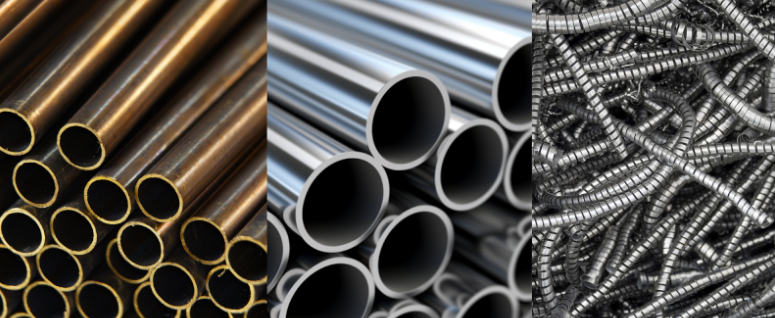
Metal machining dominates product manufacturing because metals offer unmatched combinations of strength, durability, and thermal resistance. However, not all metals behave the same under a cutting metal machine. The differences in machining metalworking characteristics directly impact your costs, lead times, and quality outcomes.
Aluminum Alloys
Aluminum is the workhorse of CNC machining—and for good reason. According to manufacturing experts at Hubs, Aluminum 6061 is the most common and lowest-cost metal for CNC machining, offering an excellent strength-to-weight ratio and exceptional machinability.
What makes aluminum so easy to machine? Its low cutting resistance allows for high spindle speeds and rapid material removal rates. You get faster cycle times and reduced tooling costs compared to harder metals. However, aluminum's softness creates its own challenge—the material can stick to cutting tools, forming built-up edge that compromises surface finish.
Key machining considerations for aluminum:
- Use sharp tooling with polished flutes to reduce material adhesion
- Employ high spindle speeds with controlled feed rates
- Apply coolant strategically to prevent tool loading and ensure smooth chip evacuation
- Control heat carefully—aluminum dissipates heat quickly but may deform if overheated
Different aluminum alloys serve different purposes. Aluminum 7075, commonly used in aerospace applications, can be heat treated to strength and hardness levels comparable to steel. Aluminum 5083 offers exceptional seawater resistance for marine applications. Match your alloy to your product's functional requirements.
Stainless Steel
When your product needs corrosion resistance combined with strength, steel machining with stainless alloys becomes essential. Stainless steel 304 and 316 are the most common choices, offering excellent mechanical properties and resistance to most corrosive environments.
But stainless steel presents challenges that aluminum doesn't. Higher cutting resistance generates heat quickly, leading to accelerated tool wear if parameters aren't carefully controlled. Work-hardening can occur during machining, making subsequent passes more difficult.
Successful stainless steel machining requires:
- Rigid tooling and stable fixturing to prevent vibration
- Carbide tools with heat-resistant coatings
- High-pressure coolant for effective heat control and chip breaking
- Avoiding light finishing passes that cause work-hardening
Titanium
Titanium delivers the best strength-to-weight performance of any common metal—making it invaluable for aerospace, medical, and high-performance applications. But that performance comes with machining challenges that significantly impact cost and lead time.
The core problem? Titanium's low thermal conductivity concentrates heat at the cutting edge rather than dissipating it through the workpiece. This causes rapid tool wear and potential material deformation. Machining titanium successfully demands:
- Rigid tooling with strong edge geometry
- Reduced cutting speeds but steady feed rates to minimize heat buildup
- Aggressive coolant application targeted directly at the cutting zone
- Optimized passes that avoid rubbing and thermal stress
Expect titanium components to cost significantly more than aluminum equivalents—not because the material itself is expensive, but because machining it requires more time, specialized tooling, and careful process control.
Beyond Metals - Plastics and Specialty Materials
While metals dominate product machining conversations, plastics and specialty materials serve critical roles in modern manufacturing. CNC plastic machining offers advantages including lightweight construction, electrical insulation, and chemical resistance that metals simply cannot provide.
Common Engineering Plastics
Each plastic material brings unique characteristics to the machining process:
- POM (Delrin) — The highest machinability among plastics, offering excellent dimensional stability, low friction, and minimal water absorption. Ideal when CNC machining requires high precision in plastic parts.
- Nylon — Strong and lightweight with excellent wear resistance. Commonly used for gears, bearings, and structural components requiring durability.
- Polycarbonate — Exceptional impact strength and natural transparency. Perfect for safety shields, protective covers, and optical applications.
- HDPE — High strength-to-weight ratio with good weather resistance. Suitable for outdoor applications and often used for prototypes before injection molding.
- PEEK — A high-performance thermoplastic with excellent mechanical properties across wide temperature ranges. Often replaces metal in weight-critical applications and is available in medical grades for biomedical use.
Plastic machining demands different considerations than metal work. Machine parameters like feed rates, spindle speed, and cutting depth require optimization for each specific material. Heat management becomes critical—plastics can melt or deform if cutting generates excessive temperatures.
Specialty Materials
Beyond standard metals and plastics, some products require machining epoxy composites, fiberglass, or other specialized materials. These often demand:
- Specialized cutting tools designed for abrasive materials
- Dust extraction systems to manage particle generation
- Modified cutting parameters to prevent delamination or fiber pullout
- Enhanced operator protection from potentially hazardous dust
The key to successful material selection? Start with your product requirements and work backward. What mechanical properties does your component need? What environmental conditions must it withstand? What surface finish and tolerances are critical? What's your budget constraint?
With these answers in hand, you can evaluate candidate materials systematically—balancing performance requirements against machining costs and lead times. The most expensive material isn't always the best choice, and the cheapest rarely delivers optimal results. Finding the right balance requires understanding how your material selection affects every downstream manufacturing decision.
Once you've selected appropriate materials, the next challenge becomes clear: how do you transition from a successful prototype to scalable production?
From Prototype Development to Production Scaling
You've selected the perfect material for your component—but here's a question that trips up many product teams: how do you ensure your prototype can actually scale to production volumes? The journey from a single cnc prototyping success to thousands of identical parts isn't automatic. It requires deliberate planning from day one.
Think of prototype machining and production machining as different destinations on the same road. The decisions you make early—geometry choices, tolerance specifications, material selections—either smooth that path or create costly roadblocks down the line. Let's explore how to navigate this journey successfully.
Designing Prototypes That Scale to Production
Here's a common scenario: your prototype looks fantastic, performs perfectly in testing, and gets enthusiastic approval from stakeholders. Then you request production quotes—and discover manufacturing costs are three times your target. What happened?
The problem often traces back to design choices that worked fine for one-off cnc prototype machining but become prohibitively expensive at volume. According to manufacturing experts at Fictiv, "There can be big differences between engineering a product for prototype and engineering the product for manufacturing."
Design for cnc machining means thinking about production realities during the earliest design stages—not as an afterthought. Protolabs emphasizes that designing with machining in mind accelerates production time and reduces costs. Their automated design analysis tools highlight features that can be adjusted for manufacturability before you commit to expensive tooling or production runs.
What specific design for machining principles should guide your prototype development? Consider these essential guidelines:
- Use standard radii for internal corners — Sharp internal corners require slow, expensive EDM operations or extremely small tools. Fillets spread loads well, while sharp corners act as stress raisers that can initiate fatigue cracks. Remember: internal corners need radii; external corners benefit from chamfers.
- Avoid deep, narrow pockets — Features with high depth-to-width ratios cause tool deflection and vibration, compromising accuracy and surface finish. If deep pockets are unavoidable, add steps or buttresses to stiffen the design.
- Specify achievable tolerances — Over-tolerancing drives costs exponentially. Use tight tolerances only on critical functional features and allow standard tolerances elsewhere.
- Design for standard tooling — Custom tools add lead time and cost. Whenever possible, use hole sizes, thread specifications, and feature dimensions that match readily available cutting tools.
- Consider workholding from the start — Parts need stable clamping during machining. Design flat reference surfaces and adequate clamping areas into your geometry.
- Minimize setups — Each time a part must be repositioned introduces potential error and adds cycle time. Consolidate features that can be machined in single setups.
- Select materials that match both prototype and production needs — Choosing prototyping materials that closely match production materials ensures a seamless transition, reducing material-related challenges as projects scale.
The goal of cnc machining prototyping isn't just validating your design—it's validating that your design can be manufactured economically at the volumes you need.
Volume Considerations in Process Planning
The transition from prototype to production machining involves more than simply running the same program more times. As volumes increase, machining parameters, tooling strategies, and quality requirements all evolve to balance speed, cost, and consistency.
Low Volume CNC Machining (Tens to Hundreds of Parts)
Low volume cnc machining serves as a crucial bridge between prototyping and mass production. According to Fictiv's manufacturing engineers, low-volume typically ranges from tens to hundreds of thousands of units, depending on the business and product.
This phase offers valuable opportunities:
- Test market response before committing to high-volume tooling investments
- Refine designs based on real-world feedback
- Validate assembly processes and identify potential issues
- Establish quality control benchmarks for larger runs
At low volumes, flexibility matters more than maximum efficiency. You might use general-purpose fixturing rather than custom workholding, accept slightly longer cycle times in exchange for setup simplicity, and rely on inspection methods suited to smaller quantities.
Scaling to Mass Production
Mass production demands different priorities. Cycle time optimization becomes critical because saving seconds per part translates to substantial cost reductions across thousands of units. Custom fixtures that reduce setup time and improve repeatability justify their upfront investment. Automated inspection systems replace manual measurement.
Manufacturing experts recommend process mapping as a technique for ensuring efficient scale-up. Start with your prototype process, mapping each phase from raw material acquisition through inspection, assembly, and shipping. Include all required inputs, actions, and outputs. This documentation helps ensure you have correct procedures, manpower, equipment, and resources in place—and provides a reference if quality issues arise during production.
One critical insight from experienced product managers: demand forecasting becomes paramount at production scale. Working with a manufacturing partner capable of scaling production up or down—from 1,000 to 100,000 units monthly using the same processes—provides flexibility that protects against both overproduction and stockouts.
The best approach? Start working with your manufacturing partner during prototyping, not after. Early collaboration ensures design decisions align with production realities, material selections support scalability, and cost projections remain accurate throughout development. This partnership approach identifies and resolves potential issues before they become expensive problems in production.
With your design optimized for manufacturing and your scaling strategy defined, one critical element determines whether your production run succeeds or fails: quality control throughout the entire process.
Quality Control and Inspection in Product Machining
Your design is optimized, your materials selected, and your production strategy mapped out. But here's the question that separates successful manufacturing from costly failures: how do you ensure every single part meets specifications? Without robust quality control, even the most sophisticated CNC equipment and perfectly optimized processes can produce inconsistent or defective machined parts.
Quality control in product machining isn't a final checkpoint—it's a continuous system woven throughout the entire manufacturing process. From the moment raw material enters the facility to the final inspection before shipping, every stage requires verification methods that catch deviations before they become expensive problems.
In-Process Quality Monitoring Techniques
Imagine catching a dimensional error after machining 500 components versus detecting it during the first part's production. That difference represents thousands of dollars in scrap, rework, and missed deadlines. In-process monitoring exists precisely to prevent this scenario.
Modern machining and finishing operations integrate multiple monitoring approaches:
First Article Inspection (FAI)
Before any production run proceeds, the first completed part undergoes comprehensive dimensional verification. Operators measure every critical feature against the engineering drawing, documenting results in a formal FAI report. This verification confirms that machine setup, tooling, and programs will produce conforming parts before committing to volume production.
Statistical Process Control (SPC)
SPC transforms quality control from reactive inspection to proactive process management. Rather than simply checking whether parts pass or fail, SPC tracks dimensional trends over time using control charts. These visual tools plot measurements from sample parts, revealing patterns that predict problems before they cause defects.
How does SPC work in practice? Operators periodically measure specific dimensions on sample precision machining parts pulled from production. These measurements feed into control charts showing upper and lower control limits. As long as measurements fall within these limits and show random variation, the process remains stable. But when points approach limits or show non-random patterns—trending upward, clustering, or cycling—operators receive early warning that something is changing.
This early warning capability is invaluable. Tool wear, thermal expansion, fixture loosening, and material variations all cause gradual dimensional drift. SPC catches these changes before they push parts out of tolerance, allowing operators to intervene proactively.
Tool Condition Monitoring
Cutting tools don't fail suddenly—they wear gradually. Modern CNC systems track spindle load, vibration signatures, and cutting forces to detect tool degradation. When sensors indicate approaching tool wear limits, the system can trigger automatic tool changes or alert operators before quality suffers.
For high-precision cnc machined components, some facilities use in-machine probing systems. Touch probes mounted in the spindle can measure critical features without removing parts from the machine. This immediate feedback enables real-time compensation for thermal growth, tool wear, or setup variations.
Final Inspection and Certification Standards
While in-process monitoring prevents most quality issues, final inspection provides the documented verification that parts meet all specifications before leaving the facility. The methods and rigor of final inspection vary based on industry requirements and product criticality.
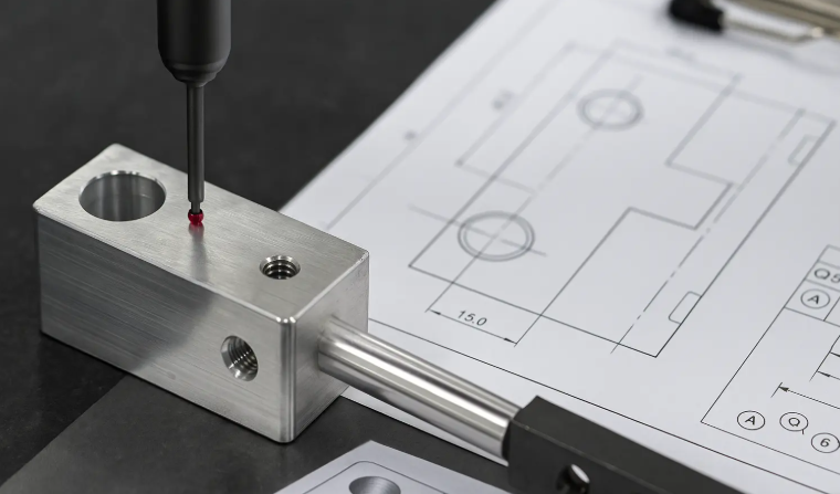
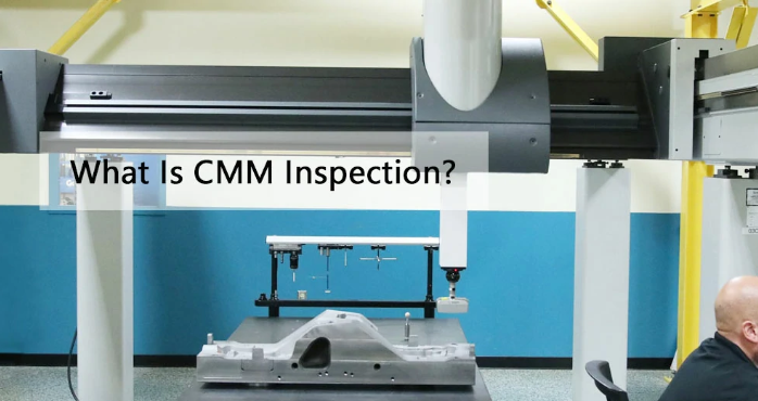
Coordinate Measuring Machine (CMM) Inspection
For complex machined metal parts with multiple critical dimensions, CMM inspection provides comprehensive geometric verification. These precision machines use touch probes or optical sensors to map part geometry in three dimensions, comparing actual measurements against CAD models with micron-level accuracy.
CMM inspection excels at verifying:
- True position of hole patterns and features
- Geometric tolerances including flatness, perpendicularity, and concentricity
- Complex contoured surfaces
- Features difficult to access with conventional gages
Surface Finish Verification
Surface profilometers measure Ra values and other roughness parameters, confirming that machining and finishing operations achieved specified surface quality. These instruments drag a precision stylus across surfaces, recording height variations that translate into quantified roughness measurements.
Visual Inspection Standards
Not every defect shows up in dimensional measurements. Visual inspection catches surface imperfections, burrs, tool marks, and cosmetic issues that affect product quality. Trained inspectors work under controlled lighting conditions, often using magnification to detect subtle defects invisible to casual observation.
For metal parts machining operations serving demanding industries, inspection results must be documented thoroughly. Inspection reports, material certifications, and process records create traceability that connects each finished component back to its raw material lot, machine, operator, and inspection results.
Essential Quality Control Checkpoints
Throughout the machining process, systematic verification ensures consistent quality:
- Incoming material inspection — Verify material certifications, dimensional conformance of raw stock, and surface condition before machining begins
- Setup verification — Confirm fixture alignment, tool offsets, and program parameters match production requirements
- First article approval — Complete dimensional inspection of initial part before production release
- In-process SPC sampling — Periodic measurement of critical dimensions with control chart documentation
- Tool change verification — Dimensional check after any tool change to confirm continued conformance
- Final dimensional inspection — Comprehensive measurement of all critical features per engineering requirements
- Surface finish verification — Profilometer measurement confirming Ra values meet specifications
- Visual inspection — Trained operator review for surface defects, burrs, and cosmetic issues
- Documentation review — Verification that all required records, certifications, and reports are complete
Industry Certifications and Quality Systems
For demanding applications—particularly in automotive, aerospace, and medical sectors—industry certifications provide independent verification that manufacturers maintain robust quality systems. These certifications aren't just pieces of paper; they represent systematic approaches to quality that have been audited and validated by accredited third parties.
IATF 16949 stands as the premier quality management standard for automotive supply chains. This certification requires manufacturers to demonstrate:
- Comprehensive quality management systems aligned with customer requirements
- Statistical process control capabilities for consistent production
- Robust corrective action processes for addressing any quality issues
- Continuous improvement programs driving ongoing performance enhancement
- Traceability systems connecting parts to materials, processes, and personnel
When sourcing precision machined components for automotive applications, IATF 16949 certification provides assurance that your manufacturing partner operates quality systems capable of delivering high-tolerance components consistently. For example, Shaoyi Metal Technology maintains IATF 16949 certification alongside strict SPC implementation, enabling their facility to deliver precision CNC machined automotive components with the documented quality verification that automotive supply chains demand.
This certification matters practically, not just symbolically. Certified facilities like Shaoyi must demonstrate SPC capabilities across their production processes, ensuring that every precision machining part reflects controlled, repeatable manufacturing rather than luck. Their approach to quality—combining certification requirements with continuous monitoring—exemplifies how modern metal parts machining operations maintain consistency from rapid prototyping through mass production.
The bottom line? Quality isn't inspected into products—it's built in through systematic process control and verified through rigorous inspection. Whether you're producing ten prototypes or ten thousand production parts, partnering with manufacturers who demonstrate certified quality systems protects your products, your customers, and your reputation.
With quality systems ensuring consistent manufacturing outcomes, the next strategic decision becomes clear: when does CNC machining make more sense than alternative manufacturing methods?
Comparing Machining to Alternative Manufacturing Methods
You understand how CNC machining delivers precision parts with documented quality—but here's the strategic question many product teams struggle with: is machining actually the right choice for your specific project? The answer depends on factors like volume requirements, geometric complexity, material needs, and cost constraints that vary dramatically between products.
The machining process excels in many scenarios, but it's not universally optimal. Injection molding, 3D printing, casting, and sheet metal fabrication each offer distinct advantages for specific applications. Understanding when to choose machine manufacturing over alternatives—and vice versa—can save significant time and money while improving product outcomes.
When Machining Outperforms Alternative Methods
CNC machining parts shine in several key situations that alternative methods simply cannot match. Recognizing these scenarios helps you make confident manufacturing decisions.
Precision Requirements
When your product demands tight tolerances—especially below ±0.005"—machining manufacturing becomes the clear choice. Injection molding and casting struggle to achieve tolerances tighter than ±0.010" without secondary machining operations. 3D printing, while improving, typically delivers ±0.005" at best, and dimensional accuracy varies significantly across different printing technologies.
Material Properties
Machined components retain the full mechanical properties of their parent material. Casting can introduce porosity and grain structure variations. 3D printed parts often exhibit anisotropic properties—stronger in some directions than others. When your application requires maximum material strength and consistency, the machining approach preserves what your material specification promises.
Low to Medium Volumes
Here's where manufacturing and machining economics become interesting. Machining requires no tooling investment—you go directly from CAD file to finished part. Injection molding demands molds costing $5,000 to $100,000+. Casting requires patterns and dies. For quantities below several thousand units, machining's per-part flexibility often beats the upfront investment that other methods require.
Design Flexibility
Need to modify a feature? Update your CAD model and reprogram the machine. With injection molding, that same change might require expensive mold modifications or entirely new tooling. Machining enables rapid iteration without penalty—invaluable during product development phases.
Surface Finish Quality
Machined surfaces can achieve Ra values below 16 microinches directly from the process. 3D printed parts typically require post-processing to approach similar quality. Cast surfaces need secondary operations for precision applications. When surface finish matters functionally or aesthetically, machining delivers superior results.
However, alternative methods outperform machining in their own domains. Understanding these trade-offs enables smarter decisions.
Cost-Volume Decision Framework
The relationship between production volume and manufacturing cost drives most process selection decisions. Each method has a "sweet spot" where its economics make the most sense.
Understanding Cost Structures
Machining costs remain relatively linear—each part costs roughly the same whether you're making 10 or 1,000. Setup time gets amortized across more parts, so there's modest volume benefit, but material and machining time dominate per-part costs.
Injection molding follows a completely different curve. That $25,000 mold represents a fixed investment. Spread across 100 parts, it adds $250 per unit. Spread across 100,000 parts, it adds just $0.25 per unit. Meanwhile, actual molding costs are extremely low—often under $1 per part for simple geometries.
3D printing occupies middle ground. No tooling investment, but per-part costs remain high regardless of volume. Material costs and machine time don't improve significantly whether you print one part or one hundred.
Casting and sheet metal fabrication require tooling but offer excellent material utilization at volume. Per-part costs drop substantially as quantities increase, though not as dramatically as injection molding.
| Manufacturing Method | Ideal Volume Range | Geometric Complexity | Material Options | Typical Lead Time | Relative Cost Per Part |
|---|---|---|---|---|---|
| CNC Machining | 1-10,000 units | High (limited by tool access) | Excellent (metals, plastics, composites) | 1-3 weeks | Medium-High (stable across volumes) |
| Injection Molding | 5,000+ units | Very High (complex internal features) | Good (thermoplastics, some thermosets) | 4-12 weeks (including tooling) | Very Low at volume (high tooling investment) |
| 3D Printing | 1-500 units | Highest (internal channels, lattices) | Limited (specific polymers and metals) | 1-2 weeks | High (minimal volume benefit) |
| Metal Casting | 500-50,000 units | Medium-High (draft angles required) | Good (aluminum, steel, iron, bronze) | 4-8 weeks (including tooling) | Low-Medium at volume |
| Sheet Metal Fabrication | 100-100,000 units | Medium (bends, holes, formed features) | Good (steel, aluminum, stainless) | 2-4 weeks | Low at volume |
Making the Decision
Use this framework when evaluating your options:
- Prototype quantities (1-10 parts) — Machining or 3D printing typically wins. No tooling investment, fast turnaround, design changes cost nothing extra.
- Low volume production (10-1,000 parts) — Machining often remains cost-competitive. Calculate whether tooling investment for alternatives pays back within your production run.
- Medium volume (1,000-10,000 parts) — The crossover zone. Compare total program costs including tooling amortization, per-part costs, and lead time implications.
- High volume (10,000+ parts) — Injection molding, casting, or sheet metal typically dominate on cost—if your geometry and material requirements align with these processes.
Consider lead time implications alongside cost. Machining delivers parts in days to weeks. Injection molding requires weeks to months for tooling before production even begins. If time-to-market matters more than per-part cost, machining's speed advantage becomes significant.
Also factor in design maturity. Early-stage products facing likely revisions benefit from machining's flexibility. Mature, stable designs justify tooling investments that dramatically reduce per-part costs at volume.
The bottom line? No single manufacturing method wins universally. Smart product teams evaluate each project's unique requirements—volume projections, tolerance needs, material specifications, timeline constraints, and budget limitations—then select the method that optimizes their specific priorities. Often, the optimal approach combines methods: machined prototypes for development, transitioning to molded or cast production once designs stabilize.
With this decision framework in hand, the final step becomes clear: finding a manufacturing partner capable of guiding you through these choices and delivering quality results regardless of which path you choose.
Selecting the Right Manufacturing Partner for Your Products
You've mastered machining fundamentals—from process selection and material choices to tolerance specifications and quality systems. But here's the final question that determines whether all this knowledge translates into successful products: how do you find a manufacturing partner who can actually deliver?
Choosing the wrong partner leads to missed deadlines, quality issues, and frustrating communication breakdowns. The right partner becomes an extension of your engineering team—offering technical guidance, solving problems proactively, and scaling seamlessly as your product succeeds. Let's explore how to identify partners worthy of that trust.
Evaluating Manufacturing Partner Capabilities
Not all machine shops are created equal. A facility perfect for one-off prototypes might struggle with production volumes. A high-volume manufacturer might lack the flexibility your early-stage development requires. Matching partner capabilities to your specific needs demands systematic evaluation.
Start with certifications and quality systems. As we discussed in the quality control section, industry certifications provide third-party verification of manufacturing capabilities. But different industries demand different certifications:
- Automotive applications — IATF 16949 certification is essential. This standard ensures suppliers maintain quality management systems capable of consistent, documented production. Partners lacking this certification may struggle to meet automotive supply chain requirements.
- Aerospace components — AS9100 certification demonstrates compliance with aerospace-specific quality and traceability requirements.
- Medical devices — ISO 13485 certification indicates quality systems designed for medical device manufacturing, including biocompatibility considerations and enhanced documentation.
- General industrial applications — ISO 9001 provides baseline quality management verification suitable for many commercial products.
Beyond certifications, evaluate actual cnc capabilities. Modern machining technology varies dramatically between facilities. Key questions include:
- What machine types and sizes does the facility operate? 3-axis, 4-axis, or 5-axis milling? Multi-axis turning centers?
- What tolerance ranges can they reliably achieve? Request capability studies or historical quality data.
- What inspection equipment is available? CMM machines, surface profilometers, optical comparators?
- How do they implement SPC and in-process monitoring?
Assess scalability and flexibility. Your prototype today might become thousands of production units next quarter. Partners should demonstrate clear pathways from low-volume industrial machining to high-volume production without requiring you to switch suppliers mid-program. Ask about:
- Capacity for scaling production up or down based on demand
- Experience transitioning customers from prototype to mass production
- Flexibility to handle urgent prototype requests alongside ongoing production
For automotive applications specifically, Shaoyi Metal Technology exemplifies this scalability approach. Their facility handles everything from rapid prototyping to mass production using consistent processes and quality systems. When urgent projects demand immediate response, their one-day lead time capability for priority work ensures development schedules stay on track. Whether you need complex chassis assemblies or custom metal bushings, their cnc machine and fabrication capabilities scale with your program requirements.
Evaluate communication and technical support. Engineering machining projects rarely proceed without questions, challenges, or design refinements. How responsive is the potential partner? Do they offer:
- Design for manufacturability feedback before production commits?
- Technical consultation on material selection and process optimization?
- Clear communication channels with English-speaking engineering staff?
- Proactive updates on production status and any potential issues?
The best partners identify problems before they affect your schedule and propose solutions rather than simply reporting failures.
Starting Your Product Machining Project
Ready to move forward? Use this comprehensive partner evaluation checklist to systematically assess potential manufacturing partners:
- Certifications — Verify relevant industry certifications (IATF 16949, AS9100, ISO 13485, or ISO 9001) match your application requirements
- Equipment capabilities — Confirm machine types, sizes, and axis configurations support your part geometries and tolerance specifications
- Quality systems — Evaluate SPC implementation, inspection equipment, and documentation practices
- Scalability — Assess capacity for transitioning from prototype through low-volume to mass production
- Lead time performance — Request typical lead times for prototype and production quantities; verify expedite capabilities for urgent needs
- Material expertise — Confirm experience with your specific materials and any specialty alloys or plastics
- Technical support — Evaluate DFM feedback capabilities, engineering consultation availability, and problem-solving approach
- Communication responsiveness — Test response times and clarity during the quoting process
- Reference customers — Request references from similar industries or applications
- Geographic considerations — Factor shipping costs, time zone alignment, and supply chain resilience into your decision
Preparing your project for success. Once you've selected a partner, set your project up for smooth execution:
Provide complete technical packages including 3D CAD files, 2D drawings with GD&T callouts, material specifications, and surface finish requirements. Clearly identify critical dimensions versus general tolerances. Communicate your volume projections and timeline expectations upfront.
Engage early in design discussions. Partners with strong modern machining expertise can identify manufacturability improvements that reduce costs without compromising function. This collaborative approach—rather than simply throwing drawings over the wall—produces better outcomes for everyone.
Establish clear quality expectations from the start. Define inspection requirements, documentation needs, and acceptance criteria before production begins. For automotive programs, ensure your partner's quality systems align with your OEM customer requirements.
Plan for iteration. First articles rarely reveal zero issues. Build time into your schedule for first article review, potential adjustments, and production qualification before committing to delivery dates you've promised downstream customers.
The path forward. Product machining transforms raw materials into the precision components that power modern products—from automotive systems to medical devices to consumer electronics. The machining technology and quality systems available today enable faster development, tighter tolerances, and more reliable outcomes than ever before.
But technology alone doesn't guarantee success. The manufacturing partner you choose determines whether your designs become reality on time, on budget, and at the quality levels your products demand. Whether you're developing your first machined component or optimizing an established production program, investing time in partner selection pays dividends throughout your product lifecycle.
For teams focused on automotive applications, exploring certified partners with proven machining and fabrication capabilities accelerates your supply chain development. Shaoyi Metal Technology's precision CNC machining services offer one pathway—combining IATF 16949 certification, rapid prototyping capabilities, and production scalability that automotive supply chains require.
Whatever your application, the principles remain consistent: match partner capabilities to your specific requirements, verify quality systems through certifications and references, and build collaborative relationships that support your products from first prototype through ongoing production. Do this well, and product machining becomes not just a manufacturing process—but a competitive advantage.
Frequently Asked Questions About Product Machining
1. What does a production machinist do?
A production machinist operates CNC and mechanical equipment to manufacture precision metal parts using blueprints, CAD/CAM files, and technical specifications. They set up machines, select appropriate cutting tools, program toolpaths, monitor production quality through SPC methods, and perform dimensional inspections. Production machinists transform raw materials into finished components for industries like automotive, aerospace, and medical devices, ensuring parts meet tight tolerances often within ±0.001 inches.
2. What is the difference between CNC machining and traditional machining?
CNC machining uses computer numerical control to automate cutting tool movements through programmed G-code, delivering exceptional repeatability and precision across thousands of parts. Traditional machining relies on manual operator control, introducing human variability. CNC technology enables complex 3D geometries, faster production cycles, and tolerances as tight as ±0.0002 inches that manual methods cannot consistently achieve. Modern facilities like IATF 16949-certified manufacturers leverage CNC capabilities with SPC monitoring for automotive-grade quality.
3. What is the highest paying machining job?
Tool pushers earn the highest machining salaries ($45,500-$122,500), followed by machine shop supervisors ($58,000-$90,000), gear machinists ($53,000-$90,000), and precision machinists. Master machinists and prototype machinists also command premium wages due to their specialized skills in complex part production. Higher-paying positions typically require expertise in multi-axis CNC programming, tight-tolerance work, and quality management systems like those used in certified automotive manufacturing facilities.
4. When should I choose CNC machining over injection molding or 3D printing?
Choose CNC machining when you need tight tolerances below ±0.005 inches, superior material properties from solid stock, or quantities between 1-10,000 units. Machining requires no tooling investment, enabling rapid design iterations during development. Injection molding becomes cost-effective above 5,000 units but requires expensive molds and weeks of lead time. 3D printing suits complex internal geometries in small quantities but delivers limited material options and higher per-part costs at volume.
5. What certifications should a machining partner have for automotive components?
IATF 16949 certification is essential for automotive machining partners, verifying comprehensive quality management systems, Statistical Process Control capabilities, traceability, and continuous improvement programs. This certification ensures manufacturers can deliver high-tolerance components consistently with documented quality verification. Partners like Shaoyi Metal Technology combine IATF 16949 certification with rapid prototyping capabilities and one-day lead times for urgent projects, supporting seamless scaling from prototype to mass production.